Hi,
I need some serious help. A friends Avi labs amplifier has gone dead in one channel with 1v output. He's not sure if output shorted or not but sounds like it may have.
There are no fuses, or burnt components! but the right channel does not have any sound and has 1v output.
I have the amplifier with me so I have lots of pictures.
I'm not new to this forum but far from a pro in terms of trouble shooting.
I tested with a MM and the amplifier off all the output transistors and they all measure fine?
Attachments
Time for dim-bulb tester, disconnect speakers, measure the voltages on the amp boards to see where discrepancies between left and right are - obviously the supply rails are worth testing first, then follow the signal path back from the output: drivers, bias network, etc etc.
Having a good and bad channel means lots of tests can be done without having to understand the circuitry, just match up the two channels node-for-node and compare.
Having a good and bad channel means lots of tests can be done without having to understand the circuitry, just match up the two channels node-for-node and compare.
Hi Mark,
The supply rails are fine so is the power source. The preamplifier is fine and all the output transistors measure fine when tested in diode mode!
What voltage am I looking for and where do I test for that. Thanks
The supply rails are fine so is the power source. The preamplifier is fine and all the output transistors measure fine when tested in diode mode!
What voltage am I looking for and where do I test for that. Thanks
A service manual with a schematic will help, they usually show important voltages to measure, usually referenced to chassis ground.
As Mark said do a 1:1 channel comparison.
As Mark said do a 1:1 channel comparison.
I would look around where the burnt resistors are firstly.
With your bulb connected as a ballast for the supply, compare side to side.
You will soon find the error.
With your bulb connected as a ballast for the supply, compare side to side.
You will soon find the error.
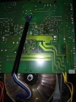
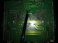
Do you have this 1 volt on the coil that is visible in the pictures as well as at the speaker terminals?
@ JonSnell There no burnt components!!! No burnt resistors
Hi Mooly, I only tested the speaker terminals, the coil is under the board. I can probably do it over the board if I note the pins. Its not just the voltage there is no audio either!
will send better pics later today
Hi Mooly, I only tested the speaker terminals, the coil is under the board. I can probably do it over the board if I note the pins. Its not just the voltage there is no audio either!
will send better pics later today
A service manual, circuit drawing or a block diagram would be helpfull to pinpoint the origin of the odd 1V dc on an output. Most amplifiers have a classic topology with differential input (single or true diff pair), voltage amplifiers with bias in a branch, and an current amplification stage. Added circuitry as current mirrors and protection alongside.
Now this 1V dc, is it stable or wobling a bit? If a scope is available, is noise present?
Pure (unwanted) dc can come from various sources: unbalanced input due ground failure, dc feedbackloop with internal error, small current difference between top and bottomsides around bias circuit, overheated but yet normal looking (emitter-)resistors... Quite a lot to check.
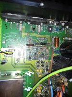
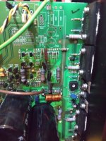
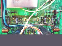
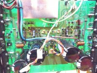
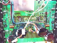
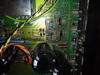
As said above, without drawings just compare all semiconductorlegs left and right until the difference is found. Draw a arrow on a photo pointing to this and post it here. On the second posted photo there are some clues already visible about the topology.
Oh, give exact name of brand and model: a drawing might wander on the internet in disguise.
Now this 1V dc, is it stable or wobling a bit? If a scope is available, is noise present?
Pure (unwanted) dc can come from various sources: unbalanced input due ground failure, dc feedbackloop with internal error, small current difference between top and bottomsides around bias circuit, overheated but yet normal looking (emitter-)resistors... Quite a lot to check.
As said above, without drawings just compare all semiconductorlegs left and right until the difference is found. Draw a arrow on a photo pointing to this and post it here. On the second posted photo there are some clues already visible about the topology.
Oh, give exact name of brand and model: a drawing might wander on the internet in disguise.
Last edited:
I asked about the coil in case what you were reading at the terminals was just a random floating voltage perhaps because of some speaker relay being open... while the real issue could be a high DC offset within the amp.
1 volt as a DC fault is a bit unusual although certainly not impossible. Check the offset within the amp to be sure.
1 volt as a DC fault is a bit unusual although certainly not impossible. Check the offset within the amp to be sure.
Added:
there is no audio either
Feels like an input problem. Diff pair out of balance, one side in saturation.
Inputs are near the yellow caps right next to the lightning symbols (I guess).
there is no audio either
Feels like an input problem. Diff pair out of balance, one side in saturation.
Inputs are near the yellow caps right next to the lightning symbols (I guess).
There is no relay! When you switch on the amplifier a buzzing sound can be heard from faulty channel. Its not the preamplifier section I already tried swapping left and right channels!
update with pics in a bit
update with pics in a bit
Pictures 🙂
Attachments
-
 IMG_20190729_203135842.jpg806.1 KB · Views: 152
 -
 IMG_20190729_203123977.jpg654 KB · Views: 145
 -
 IMG_20190729_203108622.jpg744.6 KB · Views: 146
 -
 IMG_20190729_203102292.jpg825.9 KB · Views: 207
 -
 IMG_20190729_203100883.jpg821.2 KB · Views: 213
 -
 IMG_20190729_203042273.jpg568 KB · Views: 221
 -
 IMG_20190729_202915612.jpg586.4 KB · Views: 222
 -
 IMG_20190729_202907582.jpg520.6 KB · Views: 223
Last edited:
Your best bet is to carefully compare all the DC voltages in the good channel, with those in the bad channel. Draw pcb sketches of parts of both channels, and label the voltages of all the nodes.
Last edited:
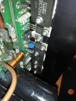
There is some rework aroud TR38 on the copper side, a little burned.
Are the connections there ok?
Power off and check from TR38 pin to corresponding connected component on topside to ensure proper connection. Else rework with copper wire. Repeat for all TR38 pins.
Check voltages L/R on caps within the circuit too.
Are the connections there ok?
Power off and check from TR38 pin to corresponding connected component on topside to ensure proper connection. Else rework with copper wire. Repeat for all TR38 pins.
Check voltages L/R on caps within the circuit too.
Hi Marsbravo, I did one transistor out but dont think it was that one. No other work has been done to this as I am the only person that has opened it!
Checking the capacitors sounds like as easier option I will try that 🙂
Checking the capacitors sounds like as easier option I will try that 🙂
Just be sure TR38 is connected properly. It might seem ok, but if one soldering is bad, you're gone...
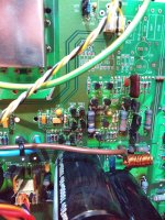
Also check these small yellow block smd cap's.
Also check these small yellow block smd cap's.
update!
I replaced all the small transistors on the mainboard and same result!
They were cheap under £10 as less risky than testing all the parts but unfortunately still faulty. I have now spent a further £17 to replace all the output transistors.
None of this has been easy and its probably one of the hardest things I have done!
I just watched lots of online videos to test the transistors and they all test fine! Could the condition be different under high voltage?
Attachments
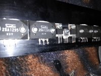
You might have an open feedback resistor there (or a bad solder joint / trace / via in the feedback path accomplishing the same). Now finding it without a schematic is another story, though I imagine it would be a 1-2 W part, not a 1/4 W. That unfortunately is the crux of complex DC-coupled amplifiers, it may take only one small, seemingly insignificant part to be bad for the whole thing not to work.
- Home
- Amplifiers
- Solid State
- AVi labs amplifier 1v DC offset