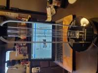
Hi! Some years ago I asked my self how to change the diode laser to the laser pickups. I bought this cd, very similar to P-D70 and P-D90 and equal to P-DX500, I saw and it seemed very interesting. When arrive it hardly could read any cd.
One focus coil was unsticked from the lens, I stick them with glue and it went ok.
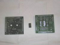
I tried to change the laser diode and to adjust watching the RF signal. Here I realized that to changing the diode is not as easy as appears. Then I bought some genuine and fake LT022mc diodes, and without power meter it was a mess. Besides, some adjusts are very critics. All tryings only was getting to worse the situation. When I broke a corner in the flat cable I decided to stop, until getting more knowledge.
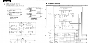
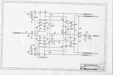
As I said the clue was in the manual of the Pioneer P-D70.
Now I decided that this moment arrived, and finally the cd is playing
again.
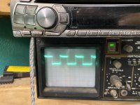
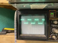
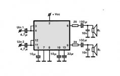
The process was similar to the other laser pickups. To conect with a flat cable, put it front a mirror, force the laser power, oscilloscopes, power supply and low frequency generator, as usual.
One problem was that I had to build a "excentric screwdriver" for to adjust the pickup. With the fingers or other tools was impossible.
Another thing I saw is that the laser I placed was dead. It was dued to power laser adjust in the laser pickup, if you force it you can break the laser easyly. For to adjust is very important the lase power meter. For to adjust with oscilloscope I use the lowest power as possible.
Then I placed the laser. I adjusted the laser power to 260uW.
The cd player was totally manipulated and out of parameters. At first the cd was totally dead. It cost me a lot to get anything at first.
For to adjust Tracking Balance was necesary to trick the cd lowing the Tracking Gain. Some adjust was easy and clear, and other impossible to perform due it's necesary a external device.
I did not adjust "grating" because I saw while I was adjusting that waves a-b-c-d get disajusted. I saw the grid with a lens and I placed the grating by way of were placed ortogonally the track in the disc, said in other words, the grid were placed 90º to the cd track angle. I don't get risk to adjust and waste all the work.
Another critical parameter was the spindle motor height. And the most difficult was the "spindle motor horizontal adjustment in tangential direction". This causes that some disc reads at the begining well and not a the end and viceversa.
And that's all.
In the process were some more problems, but to tell the entire story could be a nighmare.
In spite all problems, I tried to repair it at all costs because I saw it was a very interesting device, and very educational. I learned a lot with it an their manual.
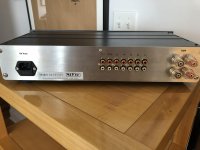
In the video appears a grey aluminium Pioneer PD-6010 with a PWY004, that is very similar to the VWY-063 from the P-DX700. It looks to have a LT022MC, but "unfortunately" these laser unit is perfect.
Pics
Pioneer P-DX700 VWY061 VWY063 PWY003 - Google Photos
Video
Pioneer P-DX700 VWY061 VWY063 PWY003 laser pickup with new LT022mc laser - YouTube
 😱
😱


