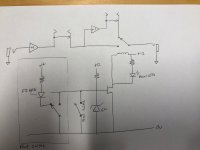
One of my amps has an fx loop with a weak buffer and loses a lot of high end with a pretty short cable run - even worse, when I try to use line level effects (with a 10k input impedance) the signal drop is huge. I'm going to put together an op amp based buffer and thought I'd fancy it up with 1 or 2 relay switchable loops. I want to keep the box close to the amp with a pedal for actuating the relays
I sketched up a pseudo schematic/block diagram for feedback before I start to do a little board layout.
Potential parts:
https://www.ti.com/lit/ds/symlink/opa1641.pdf?ts=1594314003691&ref_url=https%253A%252F%252Fwww.ti.com%252Fdocument-viewer%252FOPA1641%252Fdatasheet
https://www.mouser.com/ProductDetail/863-SZNUD3112LT1G
https://www.mouser.com/datasheet/2/307/en-g6a-1148492.pdf
I sketched up a pseudo schematic/block diagram for feedback before I start to do a little board layout.
- My pedal supply has a 12v @ 200mA output that I would like to use. It actually has two that can be paralleled but I want to start with a budget of 200mA.
- The analog circuit would have an op amp at the input as the primary buffer. I'd use a rail-to-rail part for headroom. I think I'd put another buffer at the send side of each loop as well. Basic stuff, non-inverting voltage follower AC coupled with a 1/2Vcc rail for bias.
- The loops would be switching TS jacks half normalled together (plugging into the send doesn't break the path, plugging into the return does) - 1 loop would be hard wired, the second and maybe third would be relay switchable.
- The relays would be 12v units with modest coil currents. I found some miniature relays that use less than 50mA each
- The relay switching would be accomplished with NUD3112 parts. They are cheap little drivers with built in protection. I'd pull their gates up to 5vDC with a resistor and zener and short the gate to ground to change relay states
Potential parts:
https://www.ti.com/lit/ds/symlink/opa1641.pdf?ts=1594314003691&ref_url=https%253A%252F%252Fwww.ti.com%252Fdocument-viewer%252FOPA1641%252Fdatasheet
https://www.mouser.com/ProductDetail/863-SZNUD3112LT1G
https://www.mouser.com/datasheet/2/307/en-g6a-1148492.pdf
Attachments

> NUD3112 parts. They are cheap little drivers with built in protection.
You seem to still need some series resistance between the "gate" (really Zeners) of the NUD3112 and the idiot plugging a 100 Watt loudspeaker amp output into the pedal jack. (Strange things happen on stage.) Since it seems to be a hi-hi-Z input, 30K is probably good.
https://www.onsemi.com/pub/Collateral/NUD3112-D.PDF
Oddly there is no Rating on "gate" current. But Fig 7 implies it can take 100+mA, though obviously only in bursts. With 33k in series, a 50V bad-signal only makes 1mA current and 15mA heat, which the Zener should stand. 120V makes 3.2mA, 50mW, so it may survive US power lines. I hope to never find 120V in my pedal jack but the 33k 1/2W is cheap and has no ill-effect. (1/4W will survive days at 60V and saves a millimeter of space and a penny of cost.)
Great insight, thanks. I was thinking of using a din connector for the switching signals to save space. Would you still recommend a series resistor?
I had a little time to start a layout. It's not finished but I wanted to post an "in process" since it's break time. My head is spinning from following all the jack pins (I'm using the Neutrik stacked/switching TS jacks to save space). I think I have the audio routing correct from jacks to relays. The op amp (I decided to only cram one buffer in there and make the switchable loops true-bypass) is correctly laid out I think. I kept the grounds isolated for now and left room for a jumper to join them.
Attachments
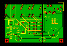
Mounting holes look a bit small to me for M3 fixing screws and need more distance to the corners.

If anyone is bored and wants to double check some of the more intimate routing details I've linked some datasheets below. Once my parts arrive I'll double check fit and pull the trigger on a few PCBs.
NSJ8HC | Neutrik
https://www.mouser.com/ProductDetail/653-G6A-274P40-DC12
https://www.mouser.com/ProductDetail/863-SZNUD3112LT1G
https://www.ti.com/general/docs/suppproductinfo.tsp?distId=26&gotoUrl=http%253A%252F%252Fwww.ti.com%252Flit%252Fgpn%252Fopa1611
NSJ8HC | Neutrik
https://www.mouser.com/ProductDetail/653-G6A-274P40-DC12
https://www.mouser.com/ProductDetail/863-SZNUD3112LT1G
https://www.ti.com/general/docs/suppproductinfo.tsp?distId=26&gotoUrl=http%253A%252F%252Fwww.ti.com%252Flit%252Fgpn%252Fopa1611
It lives!
I forgot to buy the pull-up resistors for the zeners so I had to daintily use through hole equivalents. I tested the switching with a jumper but I’ll make foot switch pedal this weekend. It’s very transparent and there’s no treble loss now.
I forgot to buy the pull-up resistors for the zeners so I had to daintily use through hole equivalents. I tested the switching with a jumper but I’ll make foot switch pedal this weekend. It’s very transparent and there’s no treble loss now.
Attachments

- Home
- Live Sound
- Instruments and Amps
- A remotely switchable FX loop with buffer