Simple FM transmitter problem

Hello,

I have built a simple FM transmitter, the FM stage of which is a copy of a very popular diy simple FM transmitter that flows around the net. I attach the schematic of the circuit I built.

My problem is that I can't get it to transmit reliably. After much experimenting with the variable cap, I have managed to sometimes transmit at about 106-107 MHz.

The problem (thus "sometimes transmit") seems to be the antenna to me, but I have little knowledge in RF. Here is the situation I encountered that got me to "blame" the antenna: leaving the circuit alone I would only get hiss at the receiving end (a FM radio), but sometimes, if I approached my hand close to the antenna, I would pick up the clear signal I wanted. So my guess was that my body acted as an antenna etc.

My antenna is a ~21cm long, 22awg insulated solid core wire. Is there a way to determine a proper antenna for this circuit? Or could the malfunction be anything else?

Attachments

  • Schematic.JPG
    Schematic.JPG
    56.3 KB · Views: 172

Theoretical: distributed gap concept applied to tapewound core

Ferrite and powdered iron toroids have an effective distributed gap.

Distributed gaps are used in some industrial transformers.

I unwound a tapewound toroid I found in an old piece of test equipment that was discarded and was surprised to find it had a gapped tapewound core. The whole thing had an epoxy coating, which is typically only done with silicon steel tape and not other alloys.

Another smaller one I unwound had no gap.

I got the harebrained idea to try cutting two gaps partially (about 2/3) the height of the core on opposite sides (Dremel tool and 0.023" diamond wheel), 180 degrees apart on opposite sides (top @ 0 degrees, back at 180 degrees, for visual reference).

I debated whether I could cut deep enough to go all the way thru or if I should...I figured the epoxy would keep the steel tape from unwinding, but two partial cuts ended up being the way I went.

Any magnetophiles have knowledge about the effect of an incomplete gap (not assumptions- I have made too many myself already!).

This is about the physics, not whatcha gonna do next & how.

I do have a toroid winder in the garage I took apart many years ago to 'modernize'. This might be the year...

Thanks

Murray

HK PM660 - What do with amp sections?

Can I bridge two HK PM660s? Or use them as monoblocks?

Hi All-

I have two Harmon Kardon PM660s with bad tone board sections. They seem to both work fine with the 'main direct' switch which bypasses the boards. I've tried to troubleshoot the boards but it's beyond my ability, and my focus now is building an Aleph J so less interested in spending much more time on it.


So, with the two amp sections could I bridge them or use them as monoblocks? I would need to do more research but not sure how that works. I could also use the amp section to make a 660 power amp.


Basically looking for something interesting to try and a fun project. Or just try to sell them as-is and put the money towards AJ.

8 ohm woofer+ 4 ohm tweeter: is it possible?

Hi guys!
First of all, I apologize for my ignorance and for my continuos newbie questions🙁
Well I explain my project: I've an 8 ohm full-range driver that I want use without any filter.
I would to add a 4 ohm tweeter filtering it by a 2,3 uF or 2,7 (at max) uF capacitor.
So the general contribution of the tweeters is very minimal.
So guys, do you consider this union of two different impedance drivers doable?😉
Thank you for your precious help and for thepatience, guys!😉
Regards

Ground Zero 10kXSPL

I have this amplifier and I am a bit lost.
It came in with blown outputs, their drivers. Outputs was IRFP460LC, their drivers was KTA1715 and KTC2814.
There was capacitor 1.2uf 250vac with broken, burned leads, replaced with 1.2uf 400Vdc. One lead of the output choke leads was desoldered from the main board, i think it cracked from vibrations and came off.

I had a great deal some time ago and I replaced outputs with IRFP360LC, gate resistors i left the same, drivers I replaced with BD140, BD139.
I replaced all IC's of the output driver board. All sot23 transistors on driver board tests fine.
The problem is that, when amp is powering up, relay turns on and off - goes in protection. I can confirm that, before protection there are DC on the output terminals.

When output driver board is pulled off, amplifiers powers on:
The power supply is working and I do get +/- rail voltages, I confirmed, that 5V,12V and 15V regulators are working. There are no DC voltage from preamp board.
Could be there still a problem in driver card or should i orderd original driver/outputs?
Sorry, i dont have right now photos with main board, i can photo it in monday.

Attachments

  • 89853.jpg
    89853.jpg
    81.1 KB · Views: 325
  • 228-GZPA 1_10000XSPL-inside-detail.jpg
    228-GZPA 1_10000XSPL-inside-detail.jpg
    57.2 KB · Views: 328
  • diver.jpg
    diver.jpg
    491 KB · Views: 334

Crossover for cheap DIY

Hi! I'm trying to make a crossover for a 2-way Bookshelf Speaker using this two drivers:
  • Woffer: Dayton Audio TCP115-8
  • Tweeter: Dayton Audio ND16FA-4

It's a try to make a cheaper version of the parts-express C-Note MT.
Here the link: C-Note MT Bookshelf Speaker Kit Pair with Knock-Down Cabinets

TCP115-8 Frequency Response Graph:
An externally hosted image should be here but it was not working when we last tested it.


ND16FA-4 Frequency Response Graph:
QqjQsdq.png


The 2nd Order Butterworth crossover I made with VituixCAD:

GN6g0gV.png


QD8susf.png


zJVXdhL.png


What do you think? I think for the price it is quite acceptable.

I appreciate any advice for a newbie 🙂

Rockford Fosgate R500X1D Repair

Hello all,

I'm having trouble with my Rockford Fosgate R500X1D car amp and was hoping to repair it myself if possible. I'm brand new to this so I'm looking for some suggestions for troubleshooting.

When I turn on my stereo, the power/protect light will not turn on. I have confirmed that there are solid connections to the main power, remote power, and ground (~12V in B+, ~11.5V in rem). I've noticed the protect light flash on a couple times as I've adjusted the power cable to ensure solid contact, but aside from this the light remains off. Disconnecting the RCA cables did not fix the problem so I'm fairly confident it's an issue with the amp rather than the subwoofer circuit. I took off the hood of the amp but didn't know exactly what to look/test for so I figured I'd get some advice before diving in. One thing I noticed was that some of the insulation had melted on a set of copper coils (see attached image). Could this be the problem or is there likely a short circuit elsewhere?

I apologize for my inaptitude and realize I'm probably underprepared to be attempting this repair, but this thing is going in the trash if I can't fix it so if anyone has suggestions for troubleshooting steps to further isolate the problem I'd really appreciate it!

Attachments

  • 20200714_212903.jpg
    20200714_212903.jpg
    1 MB · Views: 222
  • 20200714_212852.jpg
    20200714_212852.jpg
    763.1 KB · Views: 206

Simple high power BJT/MOSFET G=0.6db output with Hawksford error corrector .

This topology uses a pair of floating power supply to drive the power outputs. By using low voltage higher performance components simpler and better amp can be obtained. It can be a UHF jfet bf256A driving the pilots(bc550C/560C) that each output can have it's own forcibly if they are MOSFETs . Low voltage op amp can also be used instead of jfet to provide some extra gain of 0.6db , to allow the VAS some +/-6v dropout while driving the output rail to rail excursion with the same PSU. The op amp can also be transformed into reactor to function as Hawksford error corrector which allows class B operation with very low distortion and extended frequency response. The circuit bellow can be submitted to 60db NFB at 20Khz .


attachment.php

Attachments

  • REACTION BJT.JPG
    REACTION BJT.JPG
    311.8 KB · Views: 2,206
  • REACTION.JPG
    REACTION.JPG
    152.9 KB · Views: 1,494

FS: allo Boss v1.2 Player

I sell my allo Boss v1.2 Player.

This includes

Allo Boss v1.2 DAC
RPi 3+
16GB SD Card with Ropieee
Allo Clear Acrylic Housing
Allo 5V SMPS

Price: 99 EURO incl. shipping

Payment only with paypal.

:wave:

Attachments

  • 305685B2-1BA3-49C6-AB90-1D01C56C206D_1_201_a.jpg
    305685B2-1BA3-49C6-AB90-1D01C56C206D_1_201_a.jpg
    632.6 KB · Views: 214
  • CFFC3AE3-1DB4-40CD-9B86-72495BFE236D_1_201_a.jpg
    CFFC3AE3-1DB4-40CD-9B86-72495BFE236D_1_201_a.jpg
    446.5 KB · Views: 210
  • F59B29EE-D124-4046-BB2E-D641BA43BB84_1_201_a.jpeg
    F59B29EE-D124-4046-BB2E-D641BA43BB84_1_201_a.jpeg
    811.2 KB · Views: 220
  • 361DF184-4D8E-4019-9428-A931189A793A_1_201_a.jpeg
    361DF184-4D8E-4019-9428-A931189A793A_1_201_a.jpeg
    835.5 KB · Views: 212

VOX AC4TV Modification Project

Hi, this thread is to document what I've done so far for my own memory's sake, and to possibly gather advice from the wise and curious for future improvements to this amp.

I am an electrical engineer and started this project three years ago when I was still in university. They don't cover tubes much in class anymore, but there are some similarities to other trans-conductance devices, and working with these devices is a very interesting hobby to have.

So,

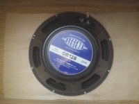
I bought the AC4TV new in 2012 and in 2014 decided to get rid of the 16 ohm 10" driver and the ported enclosure, and build a cabinet with an 8 ohm 12" driver in an open back configuration. I have heard that this amp can take the 8 ohm load, and If the power section can keep up, It may even increase the power output from 4 watts to 6? 7? maybe 8 watts? Source: Cool Information About The Vox AC4TV Series | Telecaster Guitar Forum

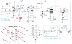
I also wanted to install a variable voltage regulation circuit to give me control over my tube overdrive sound at lower levels.

I used the information found here for the VVR circuit: InfoCentre - VCB/VVR kit (cathode biased amps)

I chose the Eminence Legend GB128 which is marketed to sound like a British greenback type speaker. I liked the strong peak at 2-3KHz in the response curve and thought it would help me achieve what I was looking for.

The first four photos are from when I did the initial work in 2014

After some tests, I found that the VVR circuit worked quite well, and I have the ability to get lots of real tube overdrive at much lower volume than before. One side effect of the VVR CCT is that the bass is accentuated as I lower the B+ rail voltage. This leaves me with about 3-6dB more bass at the lowest voltage position, relative to the rest of the frequency spectrum, when compared with full voltage operation of the tubes. The 12AX7 and the EL84 are both being fed from the VVR circuit which might account for the change in freq response since the preamp stages do not remain at a constant B+ voltage. I think it's more likely that the new lower output load load drawing too much current from the mains transformer at high output levels, causing the bass to attenuate...It's actually more of a feature than a bug though, because I don't want a ton of bass muddying my sound at higher volumes, but at lower levels a little more low end is welcomed. 🙂

After the initial work in 2014, I began to want a better tone than what I was getting; there was a pronounced peak in the response in the 2-4KHz range, right where the "VOX Chime" is probably located, but with my new cabinet and speaker, the chime was now way too pronounced. Turning the volume up was a recipe for a earsplitting chimey ringing response that just hurt to listen to.

My first try at fixing this problem was to bypass the tone stack in the amp; the tone stack is essentially a 1st order treble boost and a 1st order low pass that you can sweep between with a 500K potentiometer. This solution did cut away a good amount of the overbearing sibilance in the 2-4KHz range, but also took the rest of the treble range and a good deal of the lower mids with it.

My second try was to disconnect C15 the treble bleed cap from the second stage of the preamp, hoping to get some treble frequencies back; this worked, but it worked too well, the amp sounded more like a radio speaker then a guitar amplifier.

The third time is the charm they say, and this seemed to prove true for me as I now have the amp sounding how I like. Here is what I did:

C5 from 4n7 to 100n - To open up the preamp and let more bass frequencies through.

C4 from 220pf to 100pf - I used a frequency generator playing test tones through the amp as I alternated different capacitance values for this circuit element until the presence peak missed the 2-4KHz range instead of boosting it. The 100pf value causes the boost to occur at frequencies at and above 5KHz. It adds "air" and "presence" to the sound now, without making your ears bleed!

C3 was removed because I want to be able to turn the treble boost up or down without engaging an unwanted lowpass filter.

C15 was decreased from 470pf to 220pf; this is because the capacitor was actually draining all frequencies from about 1000-1500 and above. Now C15 only starts to drain frequencies above 2-3KHz. This has the efffect of "opening up" the voicing of the amp. If this amp were compared to a singer, it would be like the vowel shape has changed to a more open one, and the level of clairty and detail I can hear is much better now.

Overall, changing C4 has eliminated the 2-4KHz ringing that was assaulting my ears, and combined with the coupling cap change (C5) and the treble bleed change (C15), a sweetness and detail that I have never heard before has emerged. The overdrive sounds smoother and the bass is even better than it was before. I am glad this worked so well; I was worried that I chose the wrong speaker, but it turns out I just needed to voice the amp differently.

I threw in a standby switch for convenience, and I installed a wall plug so that I can plug my 1Spot pedalboard power supply right into my amp which is very convenient. No more searching for a second plug or bringing along an extension cord or splitter. I wired the plugs to the main power switch so everything turns on and off together now.

I am wondering what else I can do to improve the sound on this amp; one thing I still need to try is putting some nice tubes in. I have a ruby tubes 12AX7 and an unknown brand EL84 running right now. I am open to recommendations for tubes to try. Should I upgrade my power section? Should I get a better output transformer?

Cheers,

Peter Wing

Attachments

  • 10648258_10153281584315205_2729722405997769840_o.jpg
    10648258_10153281584315205_2729722405997769840_o.jpg
    343.6 KB · Views: 500
  • 12465925_10153281584110205_855483400448878585_o.jpg
    12465925_10153281584110205_855483400448878585_o.jpg
    377.3 KB · Views: 406
  • 12486047_10153281584020205_3136536620521186083_o.jpg
    12486047_10153281584020205_3136536620521186083_o.jpg
    291.4 KB · Views: 387
  • 12489469_10153281584260205_4092713361285789672_o.jpg
    12489469_10153281584260205_4092713361285789672_o.jpg
    406.5 KB · Views: 389
  • 20171107_085831.jpg
    20171107_085831.jpg
    90.4 KB · Views: 403
  • 20171107_090135.jpg
    20171107_090135.jpg
    109.8 KB · Views: 318
  • 20171107_090219.jpg
    20171107_090219.jpg
    90.7 KB · Views: 336
  • 20171107_090231.jpg
    20171107_090231.jpg
    117.5 KB · Views: 462
  • 20171107_090310.jpg
    20171107_090310.jpg
    91.5 KB · Views: 436
  • 7660216166_92534a7104_b.jpg
    7660216166_92534a7104_b.jpg
    232.4 KB · Views: 537

Push-Pull Bias Balancing

All,

Working on a schema for a class AB push-pull. I'm leaning towards a fixed-bias design (not sold but I've done more than a few cathode bias so, whynot) and I'm trying to work-out what all I want to do for the bias circuit. I'm going the bias/balance route; one pot for overall bias voltage level, plus two more pots (one per channel) to balance i-q for each pair of output tubes.

Almost every schema i've seen just has a pot with the wiper tied to bias voltage and each tail tied to the grid resistors. I can't say I'm entirely comfortable with that, in the even that the wiper lifts. I know "it works" since...well...its been used in various spots but I'm trying to make sure i make this as "robust as reasonable" (i know...a box of worms but i digress).

I've search around (here an other places) a bit and haven't found anything real explicit. I'm thinking of taking a similar approach to the bias supply, using a "strap" resistor from the wiper to each tail so that in the event the wiper lifts on the pot, bias is pulled to whatever the overall level is and not just left floating as 0V. Each of these strap resistors would be ~10x the pot value.

See the attached; Assuming a 1k pot, would give me about 800ohms adjustment which i'd think would be enough. Is this viable? Am I overthinking this? thoughts?

EDIT: To clarify to anyone first reading: intention for the amp is indeed HiFi, I'm simply pulling the bassman as an easy to find schematic for examples. The HK A700 is probably a more apt example of a fixed-bias amplifier with bias balancing.

Attachments

  • IMG_20200711_112501.jpg
    IMG_20200711_112501.jpg
    95.3 KB · Views: 733

A2 driving boards (for tube amps)

Hi!
Who wants A2 driver boards (boards only, no components), please PM me. I ordered a batch and expect to have them in 1 week. The bottom MOSFET is depletion mode, for a simpler CCS. The top one can be either enhancement, or depletion mode MOSFET. The board contains an anode load
resistor of a previous stage tube, a coupling capacitor, and a source follower loaded on a constant current source. One trimpot sets idle current of the source follower, another one sets bias of the power output tube. For SE amp you need one per channel, for a PP amp, of course, a pair per channel.
They were designed for my Gubernator-71 amp, to drive grids of GK-71 tubes. They would be handy as well driving GM-70 or 300B that would be a waste of precious tubes if to drive in A1 only.

Attachments

  • driver_boards.jpg
    driver_boards.jpg
    236.3 KB · Views: 1,195
  • Screenshot from 2018-11-23 19-27-58.png
    Screenshot from 2018-11-23 19-27-58.png
    43 KB · Views: 1,204

80% of an F6 - Not moving forward with Project

I went a little crazy in the last couple of months starting projects to get rid of spare parts and I just do not have the funds to move forward and complete the projects I started, so my loss is your gain. Please message for more pictures or questions. I would prefer to ONLY sell CONUS ONLY right now.

Build Parts for F6 below:

Includes completely stuffed PCB boards with Larger Super Through caps & Jensen transformers (soldered some small resistors to bottom of boards to make room for larger caps) - UNTESTED

Toshiba Matched JFETS Installed!

Power Supply board with Panasonic Snap ins (60,000 per rail) - UNTESTED

4x IRFP140s and blue LEDS Not installed

ANTEK AS-4218 transformer

2 35A Bridge Diodes

Panel Mount RCAs - not shown in pics

Shurter IEC socket w/out fuse cap (Amazon sent me three of these without fuse cap which they reimbursed me for all of them. I just used heat shrink to hold the fuses in place with no issues on 2 of my amps) - not shown in pics

Asking $300+shipping. Just need to buy a Chassis, keratherm, wiring and banana posts.

Attachments

  • IMG_1007.jpg
    IMG_1007.jpg
    1 MB · Views: 252
  • IMG_1008.jpg
    IMG_1008.jpg
    995.8 KB · Views: 253
  • IMG_1012.jpg
    IMG_1012.jpg
    1 MB · Views: 252
  • IMG_1014.jpg
    IMG_1014.jpg
    1 MB · Views: 259

HY615 cascode design

I'm documenting this project over in the Instruments forum, but since this is a general-purpose tube design question, I thought it would be appropriate here. I would appreciate any corrections or comments.

Because reasons, one of my gain stages is a cascode using two of those adorable HY615 tubes. This is my first cascode, so I followed Merlin's method. It's in the same general ballpark as his example 12AU7 (same 2.2 gm, slightly higher mu of 22 vs. 17).

Here's what I did:

  • B+ is 400V. Had to extend the chart just a touch. I chose 100V for the screen voltage, because at his suggestion of 80V, the operating point ends up pretty far down in the weeds.
  • Selected a 68k plate resistor, to get under the "knee".
  • 100V screen (red line) and 68k load line (blue line) intersect at 4.4mA, so I set the operating point at 2.2mA (green dot). I eyeballed the position of the operating point at about 2/3 between -1.5V and -3V, so I'm calling it -2.5V bias.
  • That implies a 1.14k cathode resistor. I rounded down to 1.1k, bypassed with a 10uF for now; will tweak this for tone shaping if necessary.
  • Voltage drop across the plate resistor is 150V (2.2mA across 68k). 100V across the lower tube. That leaves a drop of 150V across the upper tube. To hit 2.2mA at 150V (green dot on yellow line) looks to require about -5.2V bias, or 94.8V on the upper tube grid.
  • From a 400V B+, the closest divider I could get to 94.8V with standard resistors was 2.2M/680k, for about 94.4V.
  • 2.2M and 680k in parallel are about 520k, which for a 20Hz rolloff implies a 15nF bypass cap on the upper tube grid.

There's no spec for max heater-cathode voltage, but it's less than 100V here, so I should be safe regardless. Upper tube plate voltage is at 250, safely within the 300V spec. There's no transconductance chart, so I can't calculate the gain with any accuracy, but again eyeballing the curves around my operating point, I estimate gm at 1.07, for a gain of around 72.

SjUMnaF.png


5VNdzoJ.png


gFHdvrm.png

Rotel RB 1080-seems underpowered?

I bought this amplifier from a guy who said it had been sitting in his cuboard for the last 5 years since his upgrade and it seems to be very gutless for a 200rms amplifier-do you think it just needs to run for a while or is there anything I should do to it due to it sitting for so long-Im just supprised how little power it has given its size. The kenwood power amp it replaced was only 150rms and its half the weight!

What’s this circuit i found inside my CD player?

I just purchased an old Marantz CD-67 MKII SE, and when I opened to check the state of the internals, I found a custom circuit that seems to connect to the frontal panel buttons. What I presume is/was its power source cable has been cut.

The CD player works perfectly otherwise, but I’m curious about that hack. See photos attached.

Attachments

  • A9F2368B-6FA2-450D-A88F-BA1CEE7D9F8C.jpeg
    A9F2368B-6FA2-450D-A88F-BA1CEE7D9F8C.jpeg
    309.4 KB · Views: 201
  • 543D62C1-8E87-4133-AAAC-775C0FD9D16E.jpeg
    543D62C1-8E87-4133-AAAC-775C0FD9D16E.jpeg
    401.9 KB · Views: 209
  • F6E60B8F-EB14-471A-91F1-6D845D2AE59C.jpeg
    F6E60B8F-EB14-471A-91F1-6D845D2AE59C.jpeg
    309.1 KB · Views: 195
  • A17F45D0-4441-4D5F-A2E3-4F66BBA1C8A9.jpeg
    A17F45D0-4441-4D5F-A2E3-4F66BBA1C8A9.jpeg
    234.8 KB · Views: 204

Ultra-Low Noise Preamp Power Supply: +/-12 V, 650 mA

The Preamp Power Supply provides a +/-12 V output and can source up to 650 mA. This Power Supply features ultra-low output noise which makes it an ideal power supply for preamplifiers, headphone amplifiers, phono stages, and buffers such as my Universal Buffer. The ultra-low noise +/-12 V output is also perfect for use with my Purifi 1ET400A / Hypex NC500 Input Buffer and Pufiri/Hypex amplifier modules.

The Preamp Power Supply has the following features:

  • Fixed +/-12 V @ +/-650 mA output.
  • Ultra-low output noise and output impedance.
  • Mains voltage input with support for worldwide mains voltages and frequencies.
  • Integrated power control circuitry which supports the use of low-voltage switches, such as the anti-vandal switches popular with DIYers.
  • Support for both momentary (doorbell) and toggle switches for power control.
  • Built-in over-current and over-temperature protection on all outputs.
  • LED indication of ON and STANDBY states with support for bi-colour LEDs (both 2-pin and 3-pin types).
  • Dual LED dimmer.
  • 12 V compatible trigger output with 100 mA current limit for remote control of power amplifiers.
  • 12 V, opto-isolated trigger input.
  • 5 V @ 80 mA always-on auxiliary power supply.
  • Rising cage clamp output terminals supporting wires up to AWG 16 (1.5 mm2) in size.
  • Compact 55 x 108 mm footprint. Fits within a 1U chassis height, including safety clearances.
  • Two-layer, gold plated PCB.
  • Made in Canada.
You can find the full specifications of the Preamp Power Supply on its product page: Preamp Power Supply – Neurochrome

The power supply is currently in production. I expect to have the first batch of 10 available by the end of July with more to follow around the middle of August.

I am making the Preamp Power Supply available on pre-order special for $139. Once the first batch arrives, the price will increase to $159.

Tom

Attachments

  • PrePower_R2p0_ASSY_wText.jpg
    PrePower_R2p0_ASSY_wText.jpg
    327.7 KB · Views: 884
  • PrePower_R2p0_ASSY-2_wText.jpg
    PrePower_R2p0_ASSY-2_wText.jpg
    328.6 KB · Views: 948
  • Like
Reactions: Mike Hanson

Behringer GX110 guitar amplifier don´t work ... dead?

Good afternoon friends

I would like some help please.

My Behringer GX110 has stopped working.
Last night everything was fine and I played for 2 hours, but today when I turned it on, there was no signal.
The led does not light up when the power switch is turned on.
t seems that he was suddenly without power supply.
I've seen the fuse and I think it's fine, as well as the power cord
What damage will it be?

Thank you

Quad 707 and IQaudIO Pi-DAC+

Hi,

This may be a very simple question and perhaps something already tackled before (forgive me - I did search, but couldn't find anything conclusive)

As the title suggests, I have a Quad 707 and IQaudIO Pi-DAC+ that I would like to operate without a pre-amp.

The issue being, that the Quad 707 has an input sensitivity of 0.775V and the IQaudIO Pi-DAC+ has an output of 2V RMS.

Ideally, the volume control would be via the hardware control on the Pi-DAC+. I have tested this and it has proven to be very reliable (so far) in that it always boots into the saved state which is default at 20%.

To connect directly to the Quad, would it be sufficient to use a voltage divider? Using a divider with 10KOhm and a 6KOhm ( 0.5W 1% Vishay Metal Film) would give me a result of 2V to 0.75V - is this a sensible option?

I did consider an inline attenuator (such as Attenuators ) but these are 10db. I think this would give me a reduction from 2v > 0.63v. So may loose a bit too much?

Any suggestions gladfully welcomed 🙂

X Sim not finding frd files. Help, please

Hi Guys,

The title pretty much says it all. X Sim hs been working fine for months but, although nothing has changed on my computer that I know of, a problem has cropped up. When I measure impedance using DATS I export it as a zma file to the X Sim !FRD ZMA files folder. It shows up on the computer when I check with file explorer, but does not show up from within X Sim when I try to load it into the driver data. I'm not very computer savy so all I've done so far is to restart the computer a couple of times. I'm thinking of deleting X Sim and reloading it, but am afraid that might be a mistake. Any ideas would be appreciated!

Thanks!
Jay

Counterpoint SA3000 Preamp question

Hello All,

I have a SA-3000 that I like very much, but it has developed a problem. I do not have a service manual, so I don't know where to start finding the cause. Every now and then there is a thump followed by a drop out for about 1 second. Red LED 502,marked "No Load", in the high voltage power supply, lights for the duration of the drop out.

This can happen just a single time, or repeated every few seconds until I put the amp in standby. When I take it out of standby it plays fine. Anyone know what I should be looking at? Thanks.

Rebuilding a 2.1 speaker system and want to replace the existing controls

I've got an old Altec Lansing ACS340 3.1 computer speaker setup that has begin to give me problems with the wiring. (Loose solder joints likely from having banged it around so much.)

I like the sound well enough to not want to upgrade to better speakers, so while I am tearing them apart to re-solder the connections I thought I would also re-build the cases out of hardwood to spice them up a bit.

I would like to replace the existing Volume/Bass/Treble pots with ones that I can put on nicer knobs, but am unsure as to if they are linear or audio pots.

I found a schematic for the system and it lists all three pots as 25k, but not whether they are linear or log pots.

Anyone care to venture a guess? Thinking the volume might be audio and the other 2 linear, but no real clue. Since the whole thing was marketed as cheap computer speakers for Dell computer decades ago I'm assuming that it's whatever pots were cheapest.

I'm guessing just measuring the resist. of the pots with a multimeter would answer my question right? Measure as I sweep the dial and see if the resistance changes linear or not?!?

It would be nice to already order the new pots and be ready to build before tearing apart the speakers to test as I don't have 'other' speakers to use while these are dissassembled.

Any guesses greatly appreciated!

Thanks!

  • Locked
The Documentary Thread ⭐

Any subject (Audio, 8K Technology, Wildlife, the Humans and the Planet, Wars, History, Science, the Universe, ...) documentary you might have watched recently, you've heard of, you intend to watch soon, on TV, on HBO, on Apple, on Amazon, on PBS, on Netflix, on 4K Blu-ray, on DVD, on anything ... and everything worth mentioning if only just for fun or with a more serious tone, interest, vast space of our galaxy and stars, ... all the jazz in the world since jazz was invented and beyond ... the new jazz.

Articles, videos, trailers, reviews (your's the best), anything that support it or not, anything that you think is advancement for the knowledge, food for the brain, musically, visually, geographically, spiritually, culturally, scientifically, historically, old, new, past, present, future predictions, our planet, the other planets, electric cars, nuclear fusion energy, life after death, death before life, ... is acceptable and permissible, Including docs on building the perfect audio system by yourself.

Docs on music, concert videos, docs on Life, Love and the Blues.

Last night on Netflix I watched this documentary about ...

I recognized a familiar name ... the first mentioned below ...

PEDRO ALMODÓVAR, AGUSTÍN ALMODÓVAR and ESTHER GARCÍA - Executive Producers

Pedro Almodóvar, Agustín Almodóvar and Esther García are Executive Producers of The Silence of Others. Their production company, El Deseo, is known around the world for Pedro Almodóvar’s extensive body of cinema, including such groundbreaking films as Talk To Her and All About My Mother, both of which won Oscars and Golden Globes. Their films have premiered at Cannes, Berlin, San Sebastián, and Venice, and have won multiple Academy Awards, Goyas, BAFTAs, Cesars and European Film Awards.

And because I am familiar with this filmmaker and all his films (almost), it was an easy decision.

Filmed over six years, The Silence of Others reveals the epic struggle of victims of Spain’s 40-year dictatorship under General Franco, as they organize a groundbreaking international lawsuit and fight a “pact of forgetting” around the crimes they suffered. A cautionary tale about fascism and the dangers of forgetting the past.

The doc is only 95 minutes long, with some actual historic footage but the essence is in the faces of present people. Do we forgive, yes, do we forget, no. That's my flexible state of mind in general about life lived and life not lived. There is no one absolute definition about history; usually the victims are searching for a sense of humanity, a way to express their silence, and the perpretrators are looking for absolute silence, to never be unraveled ever.
This is normal, it's human nature @ its deepest, like a coin has two flip sides.
But I believe in the truth through history, I believe in justice if we truly want to live in a better world (or a world in silence). Without justice there is discord. But it's not just about remembering, it's about breaking silence on historical injustices, giving the voice to the victims who suffered in silence their entire lives. That's how we don't commit the same mistakes twice and more.

The visuals (people's facial expressions) tell it all, the cameras capture their silence wanting to escape. ...And everything else built around them.
The music score is delicately and perfectly well chosen. It has the right impactful and human touch.

It's a sad page of history, and one that has to be heard from their victims.
Listening to their silence in humility and respect. Giving them their peace and justice.
I highly recommend. It might not fit everyone's state of mind right now with a pandemic running around but it also might be a temporary antidote. It sure was for me...the people, their story, the music, the cameras following, ...

The Silence of Others - Award winning documentary film

From that link just above ^ click on "About" ... explore.
Even better watch the doc ... The Silence of Others

YouTube

_____

☆ This is the Documentary Thread ... a place to share, to review, to discuss, to talk about anything everything of interest in the times we are living now.

Cheers,
Bob ... stay safe, play cool, keep calm, be kind ... we're all in it closer to the heavens.

Techniques/tips for troubleshooting buzz/hum?

I've always found buzz/hum issues to be one of the hardest issues to track down in amps. Anyone have any general methods or tips to share? Is there a way to prove it is or isn't big power supply caps without spending a lot of money to replace them? Sometimes I've used the scope and see some noise only to find it isn't the noise I am hearing. Any way to tell grounding issues apart from power supply issues?

I mostly work on vintage solid state gear.

TOKIN SITs- Pairs of THF-51S and 2SK182ES

I bought over the last years some SITs from eBay watanabetomoaki.
This was a time where no matching for a pair was offered.
Meanwhile I have two pairs from Chul and one pair from pras1170 I can use for my build, so I have too much!

I just looked what I had in my basement and found two good pairs and one mediocre (and two singles).

These pairs will work for instance in Zen Mods SissySIT circuit.

So I offer here, measured in the Locky-z curve-tracer at Id = 2A and Vds = 24V

1. Pair THF-51S numbered 8 and 10, Vgs = 2,64/2,64V, perfect match

price 60 €

2. Pair THF-51S numbered 1 and 7, Vgs = 2,3/2,35V, near to perfect

price 55 €

3. Pair 2SK182ES numbered 6 and 5, Vgs = 3,2/2,9V

price 45 €

As I already told these pairs should work in Zen Mods SissySit Circuit.

Postal fees worldwide 8.-€

You will find the pairs in the picture.

The solder on the pins is only from fixing the curve-tracer wires, they were all not yet used.

Attachments

  • Generg SITs.jpg
    Generg SITs.jpg
    490.7 KB · Views: 757

Which Amp to Choose to Build

Hi Guy's I am an ex electronics tech and have not been doing that for 30 years but decided after having my plinius SA250 die (having it repaired) ....it was time to look at DIY again.

I like Class A and the simplicity of the circuits etc. The big question is what amp is the best to build. I have martin logan SL3's not an easy load but i don't play them super loud and prefer sound stage and presence over volume.

So given I use to build and design instruments in a science lab I know I can build anything no issue there just wanting advice and opinions on which amp of all these options will provide the best sound? I need Balanced input too as I run a balanced Theta Casablanca Preamp.

Thanks in Advance.

Rick

soundcraft spirit folio SX Psu improvememnt

this is a good sounding unit but it is vey easy to clip, wonder why such a large desk can run on a tiny 18-0-18 AC 600mA transformer.
Would does the worth to improve somehow PSU ?
any suggestions to easiest route to get a tangible result ? Iw would be possible to feed +-20 DC to rectifiers ?

An externally hosted image should be here but it was not working when we last tested it.


thank you

Attachments

  • Untitled.jpg
    Untitled.jpg
    53.8 KB · Views: 1,197

Protecting my power transformer (845 amp)

I'm hoping to draw on the knowledge and insight of this community to help me prevent a problem with my 845 power amp. I've attached a schematic of the circuit in question (filament circuits not shown).

I built this amp about 4 years ago, it sounds amazing and I love it. but during its life, on two separate occasions, something has happened that has rendered my power transformer inoperable. It seems as though the secondary has internally shorted. Now I believe in both cases this was in response to my rectifier tubes dying in some fashion.

In my schematic you can see the most recent design, which includes 1KV 600mA fast blow fuses in each leg of the HT secondary. I am hoping that if the rectifier dies in the future that these fuses would pop before the secondary has a chance to short.

I am wondering if there are any other suggestions anyone has to protect this (rather expensive) power transformer that I have just received from Monolith.
Any help is greatly appreciated.

Attachments

  • 845schem.png
    845schem.png
    68.8 KB · Views: 104

Toroids for sale

1. poted power transformer - Power 111VA, for Tube amp like SE GU50, 4 pcs, 30€/pcs
2. Power 400VA, Uin 230V, Uout: 4 x 110V 0.9A - for Tube amp like OTL 6C33C price 40€
3. Power 260VA, Uin 230V, Uout: 5 x 13V 4A - 35€
4. Power 260VA, Uin 230V, Uout: 5 x 13V 4A - 35€ (slim)

Transformer are unused

Shipping from Slovenia (EU)

Attachments

  • IMG_20200714_162807.jpg
    IMG_20200714_162807.jpg
    856.5 KB · Views: 285
  • IMG_20200714_162818.jpg
    IMG_20200714_162818.jpg
    854.7 KB · Views: 279
  • IMG_20200714_162946.jpg
    IMG_20200714_162946.jpg
    857.7 KB · Views: 270
  • IMG_20200714_163009_1.jpg
    IMG_20200714_163009_1.jpg
    890.2 KB · Views: 254
  • IMG_20200714_162910_1.jpg
    IMG_20200714_162910_1.jpg
    908.7 KB · Views: 251

Upgrading an Adcom GFA-555...

Hi,

I am working on upgrading an Adcom GFA-555 (mkI). I noticed there are quite a few old posts on this amp and I enjoyed reading them.

Based on this I would like to do the following:

- Recap the amp with fresh electrolytic capacitors. Nichicon Ultra Fine Gold caps for the input board. Apexjr 24.000uf 110V computer grade caps for filter caps.

- Fix the DC offset imbalance by adding a second 33.2r RN55D resistor per channel, this will go in place of the jumper next to R3 on the input PCB. I will also add a 1K trimmer between the emitters of Q1/2, and connect the wiper to the junction of the two 33.2r resistors to fine tune the DC offset.

- Increase the feedback resistor R6 to 33.1K RN55D

- Replace the ceramic 68pF capacitors (C8, C9) with silver mica 68pF 500V ones

- Replace the driver transistors Q11 and Q12, currently D525 and B595 (2sb595 and 2sd525?) with MJE15030/31

- replace the glass fuses for ceramic fuses

The power supply: I understand the 700VA 52-0-52VAC power transformer is not up to the task, and should be beefed up. Can I add a 800VA 55-0-55VAC toroid, place it in parallel to the existing toroid secondary, and combine the AC outputs at the bridge rectifier? Or am I better off building two separate power supplies, one per channel?

Overall, does the above sound like a good approach?

FS: 4x or 2x PSD2002S-16

4 like-new Eminence PSD-2002S-16 1-3/8"-18 screw-on throat drivers for sale. Bought them years ago from Danley Sound Labs off eBay as liquidated measurement samples. I never installed or used them further. I've got WAY too many other projects I'm fiddling with, so it's time to trim the fat.

In factory packaging with throat cover and magnet bumper still attached. These units have never seen use at power.
$75/piece retail on Parts Express

y5bkC3C.jpg

R8sUtO2.jpg


Willing to split as pairs but not singles.
$150 shipped to contiguous US for all 4 units
$80 shipped to contiguous US for 2 units.


Thanks!

EX1200 EQ Stetsom

Hello!


Can you please help me again? I have problem on speaker output it has 60V DC out, I have removed output FETs but the DC out still there. Rail voltages are +90-90. Amp is not in protect mode.


I don't have schematic, requested a copy from stetsom but they point me to local distributor. Appreciate if somebody has a schematic at output side and send it to me?


Thank you....

FS VFETS & Semisouth

Hi all. I sell the next impossible to find transistors. All prices + paypal fees and shipping cost

2 pairs of 2SK60/2SJ18 to 200 eur the four
6 2sk70 to 35 eur piece
4 russian KP926A to 15 eur piece
4 new semisouth SEJP120R063 to 70 eur piece

I sell because I have not time to use them and I think is better another diyer can enjoy with them.
I did not got the curves, as I did with others vfets, but I checked all to genuine vfets (around 2 ohm between D-S, and diode between G-D and G-S).
The semisouth were buyed from power electronic shop directly and never were used, so they are new.

Attachments

  • 20200712_073207.jpg
    20200712_073207.jpg
    182.6 KB · Views: 643
  • 20200712_073236.jpg
    20200712_073236.jpg
    158.1 KB · Views: 642
  • 20200712_073251.jpg
    20200712_073251.jpg
    161.5 KB · Views: 633
  • 20200712_073314.jpg
    20200712_073314.jpg
    194 KB · Views: 623
  • 20200712_073324.jpg
    20200712_073324.jpg
    134.7 KB · Views: 619

Hall VVR in an AC4TV

I'm thinking about buying the hall amplification vvr kit to replace the attenuation circuit in my ac4tv. I haven't done any amp building or modding before, and I'd like to try and make sure I can figure out how to wire it before I place the order. I know that there are the connections that need to be made; to B+ in, B+ out and ground. I can handle the ground connection, but I'm wondering, if I post a schematic of the amp, can anyone help me locate the other two circuit points? I think if I know where they are on the schematic, I'll be able to find them on the board. Thanks!

Crossover help required

Hello all,
I recently built a pair of Mltl floorstanders courtesy of Paul Kittinger, who did any amazing job for me. I’ve been using a 2x4 minidsp to perform crossover and a little eq duty but would like to build a passive crossover. My crossover skills are close to zero and I would much appreciate it if some kind person could get me started with a recommended design.
The drivers in question are:
Seas L16RN-SL 6” woofer
HiVi DMB-A 2” mid
Dayton 16FA-6 5/8” tweeter
The baffle is 8” wide.

So far, I have been using it as a 2 way, crossed at 1000hz, LR4, which seems to give me the best results. Even though my hearing range tops out at 10,000hz, I would like to try it as a 3 way.
Many thanks, stay safe.
Peter

Attachments

  • B032B415-A987-4A93-92A0-B4A9628AEAFD.jpg
    B032B415-A987-4A93-92A0-B4A9628AEAFD.jpg
    375.5 KB · Views: 104

Which one is better?

In theory, a second-order filter requires to reverse the polarity of one driver to let the sound wave in-phase at a region near the crossover point. But in practice, many designs have no reversing performed on the driver and the system's frequency response can still be flat.

In the case of both flat frequency responses, which one is better between reverse and non-reverse polarity, assume performing on the tweeter of a 2-way system? Please share your opinion. Thank you in advance

First Octave Low Pass Subwoofer Filter Suggestions

G'day.
I'm wanting to build a low pass actuve filter with maybe 4th order with a cutoff frequency around 22Hz. ie. Full output from 16Hz-20Hz, then declining in output over the 1st octave by 24dB, and so-on at higher frequencies.

The purpose is to add a 2nd smallish subwoofer to my home theatre that only produces significant output in the first octave. Without this low pass filter, the 2nd subwoofer is just adding more bass in the mid-bass and above range.

I want to fill out the 1st octave only by progressively filtering out higher frequencies that are already well produced, then raising the volume.

The idea is that instead of having a 22Hz 4th order filter order will compensate with the rising sensitivity of the subwoofer (with rising frequency), to produce a flatter frequency response (room issues not included).

I've been reading up on filters but am no expert.

Looking for suggestions (or off the shelf modules, PCBs etc). I don't intend on reinventing the filter, just implementing the best one for the application.

Crossover Inductors

I have a pair of surplus (to me) crossovers. There are some inductors on them that should be of value to someone (not me anymore as I've gone active). There are also some poly caps and resistors, but consider them free. The inductors are:

0.5mH 18g (total of 2)
1mH 15g P-core (total of 4)
0.65mH 15g P-core (total of 2)
0.13mH 18g (total of 2)

There are a few 5.6uF, 12uf, and 10uF poly caps as well.

All the above are soldered on to PCBs. So the inductors are easy to remove as the leads are fairly long. The caps are little more difficult, but should not be bneyond the capability of anyone who knows which end of a soldering iron to hold .

There's about $100 worth of inductors here if bought new, so how $35 plus shipping from 02067 (Massachusetts).

Attachments

Surge Protection

Hello everyone. I didn’t know exactly where to post this question, but, saw that this forum has a great number of participants and so I thought I’d start here.

A few weeks ago, we had a brown out, followed by a surge, which managed to take out my preamp! I won’t let this happen again, am in need of a 20 amp surge protector! Are there any specific brands, or units that anyone here would recommend?

Any and all suggestions appreciated!

Thank you,

John

Is the Bottlehead Crack comperable to any commercially made Chiense alternatives?

The Crack seems a bit pricey to me at $430 for the kit considering it comes with cheap parts and the price of the Chinese amps - which commercial alternative is there, assembled, or alas, a kit ?

1st pic is supposedly the Crack (OTL)

2nd is one of the few generic amps I could find on Aliexpress which has a transformer and comes with a schematic


3rd looks similar and uses the same tubes but I don't see the transformer

Attachments

  • crack.gif
    crack.gif
    31 KB · Views: 1,178
  • O1CN01Ohl1CF1JLznPuoPUB_!!2641881013.jpg
    O1CN01Ohl1CF1JLznPuoPUB_!!2641881013.jpg
    165.7 KB · Views: 1,075
  • TB2WnDIpXXXXXXCXFXXXXXXXXXX_!!2641881013.gif
    TB2WnDIpXXXXXXCXFXXXXXXXXXX_!!2641881013.gif
    5.6 KB · Views: 2,352

Advice on active 2/3 way design

I'm planning on building a pair of active 2 or 3 way speakers that have a pretty good LF response in a compact(ish) design. I also want to learn from the design process so I'm prepared to spend a fair bit of time prototyping. I started out looking at a coax/sub arrangement using a SEAS CN16N001/F and L26RO4Y but I'm not entirely confident the HF response of the coax will sound as good as the T35C002 tweeters I'm used to in my A26 mains.
So that got me to looking for a woofer that could work with the T35C005 (other than the A26) which led me to find the W22NX001. So now I'm thinking about using those drivers in a 40L closed box crossed over at 1500Hz. I'm thinking a waveguide might be beneficial for the tweeter and as it will be a closed box I have the option of a Linkwitz transform on the woofer. I can CNC the cabinets so incorporating the waveguide into the baffle should be simple once I've worked out the profile (which I guess will be the difficult bit). Also I plan to prototype the filters using a miniDSP before designing and building them as analogue filters.

So does that sound like a good plan or am I destined for a time consuming, expensive disappointment? Any advice gratefully received.

Vale Grant Imahara

I know Grant Imahara isn't strictly high-end audio specific but I think seeing the whole Mythbusters crew solder stuff and put neat gear together has had a positive influence on me getting here.

Disappointed to read this:
MythBusters co-host Grant Imahara dies aged 49 - ABC News
It's a shame his time came so soon.

He also did a pretty good job as Sulu in Star Trek Continues. I'm sure he enjoyed being part of that.

Measurment - B&W 705 s2

So I just got home a calibrated umik-1 microphone with an idea of changing crossover or something with my B&W 705 s2.

Current crossover is a 4,3 uf capacitor and a 4,5mH inductor giving me hipass of 4625, and a low pass of 285 first orders.

Measured approximatly 70cm away from speaker on axis on tweeter.

Is this worth fiddeling with, judging the 3,3ms timegated measurment?


- Terms of soundquality it can sound quite harsh, especially at higher volumes

Attachments

  • on-axis.PNG
    on-axis.PNG
    55.3 KB · Views: 340
  • 1.PNG
    1.PNG
    797 KB · Views: 320

Mains distribution block with DC blocking

Hello folks,

I am looking at building a four way mains distribution block and would like to build in DC blocking to see if it will make my transformer in my valve amp buzz a little less.

I have read numerous threads on DC blocking circuits here and elsewhere also and have come across a few examples where contributors have noted that the Diodes or Caps are not correctly orientated.

I have attached the circuit which I was looking at building using two large high ripple electrolytic Caps (KEMET 47,000UF 25V dc 17amp ripple rating) and two diodes (Vishay Fast Recovery 600V 20A, TO220).

I would build one filter which would feed all four sockets. I was thinking of using an aluminium chassis for the sockets, but putting the DC blocking circuit inside a plastic case which would be housed inside the aluminium case.

From my understanding, I think that this circuit is correct and will work but would greatly appreciate any comments to reinforce this (or warn against) before I build anything.

many thanks!

Attachments

  • DC_Blocker01.jpg
    DC_Blocker01.jpg
    35.3 KB · Views: 531

Guitar cab

I decided to finally get around to putting a couple of alnico USA Rola 12" drivers into a cab, that I pulled from an organ ~ 20 years ago

The drivers are double cone with Fs ~ 67Hz, Qts 1.3, but I can't find any info on them, It seems like Rola was going through some difficulties at the time & morphing into Jensen.
My guess is they were OEM for the organ company (Which I can't recall)
The code on the magnet indicates they were made in 20th week of 1973.
My main concern is to find the power rating, most speakers of the time were rated at 15 - 30 watts RMS. FWIW, they are very loud pushed with a 50 W amp, but I only did that for a couple of minutes. Cab only weighs 10Kg, very user friendly

numbers on the magnet are:
656740
23017
2857320

Attachments

  • sp3.jpg
    sp3.jpg
    27.8 KB · Views: 128

FS: Neurochrome 8X2 Preamp

Hi all,

Time has come to rehome this preamp, which is looking a bit sorry for itself.

From a functional standpoint, the PCB is 100% ok. It has 2x RCA inputs and 2x Balanced inputs + output.

The units was used with a Stepped attenuator and we gave it a torroid based psu. Sq is Fantastic, as is to be expected when talking of Neurochrome.

However, i stole the RCA sockets for another project, removed the Stepped attenuator and when I sold the Khozmo 64 step relay, it left a fairly ugly hole in the front where id roughly attached the screen and remote sensor.

I have an Alps Blue to put in and extender rod to attach it to. I have fitted a bearing to the front planel as the knob used to get stuck due to being mounted off center. This has been cured. I havent react hed the Alps blue yet, but will.

I have a black LED switch that I can included.

So 100% functional, 100% ugly.

It needs some love but its an absolute top drawer performer.

I'm looking for £150 delivered in the UK

Elsewhere will be a case by case basis for the cost of postage.

View attachment 856600
View attachment 856601
View attachment 856603
View attachment 856602
View attachment 856604
View attachment 856606
View attachment 856605
20200629_172647.jpg
20200629_172639.jpg

Peerless XLS-12 (830500) ported vs passive radiator config

Hi,

Once upon a time (like 15 years ago), I built a North Creek Thunder sub that uses XLS-12 with the 300g Mms Passive rad (830547) and a 250 Watt AB amp with a -6dB off boos around 23 hz.
The result was frightening with songs like Intergalactic by The Beastie Boys and so on. (105 dB @ 20Hz)
Some friend were even jumped out from the listening sofa (they were party people, who loved heavy basses, but they did not expected what is coming 😀)

I still have a spare driver unit, but the passive rad is not available. I found the 425g and the 600g version (830548 and 549), and also the ScanSpeak Discovery 30W/0-00-00, that looks similar by the T/S

The problem is their price. (about 120-150€ these days)

I wonder if I build a 40 Liter ported box (as the application notes suggests it) Can I get the same result as the PR version delivered?

I would use almost the same cabinet that was used with the PR version, but I would place the driver on the small side.
The box would be about 34 x 34 x 71 cm outer (28 x 28 x 63 cm internal, with heavy bracing, 3 cm side walls, 5 cm front, plywood with mdf)

I calculated 1.5 liter as the driver displacement and cca 3.5 liter for the bracing plus cca 4.1 liter for the ports.
The ports would be on the front, just like the modern PA ported subs, triangle shape on the unused space, in the corners.
2 piece 8 x 8 triangle, so the surface area (64 cm2) would be the same as the 9 cm diameter suggested port (63.62 cm2), and the 51 cm length would be untouched.

Can anyone confirm if this would be also optimal?
What can I expect compared to the PR version?

Would use a Rand MA-6S power amp in bridged mode (300W into 8 ohm) and probably some HP filter to keep the subsonics away.

Cambridge 740C not ejecting PIC12C508A

Hi,

wondering if someone can help. I acquired this CD player and it not ejecting. The mechanism is fine. The problem is I'm not getting any voltage from the motor control unit. I believe it from the chip PIC12C508A

All the voltages around the chip are fine. The components around that seem fine as I checked them with my volt meter.

I think the pins 2 and 3 are output to the motor but when the open/close button is pressed there is no voltage across those pins or the connector itself.

Also I cant seem to find D6 and D7 on the board, maybe the schematic is different to the board?

Any help appreciated!

Attachments

  • cd tray.jpg
    cd tray.jpg
    179.6 KB · Views: 99
  • IMG_20200711_175127788.jpg
    IMG_20200711_175127788.jpg
    333.2 KB · Views: 95

FS: DiyAudio Store Amp Camp Amp Parts Kit

The Amp Camp Parts Kit includes everything you need to build the Amp Camp Amp except the recommended power supply and a chassis.


Have decided to go straight to a First Watt M2 and will not be using this kit purchased from the DiyAudio Store. The package remains factory sealed and it is version 1.6. Selling for $125 (Paypal) shipped within the US.


To be clear - for sale is the "Amp Camp Amp Parts Kit Only". DiyAudio Store Link: Amp Camp Amp Parts Kit Only – diyAudio Store

Partridge audio output transformer value

Long ago, I built nifty power amps with glass-enclosed vacuum amplifying elements, esp, with motional feedback bridge circuits. So I collected a bunch of output transformers.

Sitting in my parts box for 40 yrs or so is a Partridge output transformer, a magnificent ultra-linear potted unit with all the windings brought out to pins. Seems to be CFB/0/1.7, 60 watts, about 10 lbs (might be Type P4170/1, not certain). I have a bunch of spec sheets and docs from that period and letter from Partidge, 1967. Bought from Harvey Radio in NYC. Incredible square waves pictured in the spec sheet. Needs a good home.

Can anybody tell me if this (once) magnificent unit has much value? Originally sold for $50 which would scale up to thousands today (only kidding).

BTW, I'm glad to scan and eMail the spec sheet pages to anybody interested.

Thanks for any help.
Projects by fanatics, for fanatics
Get answers and advice for everyone wanting to learn the art of audio.
Join the Community
507,772
Members
7,887,779
Messages

Filter

Forum Statistics

Threads
406,200
Messages
7,887,779
Members
507,772
Latest member
Hypertone