All,
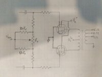
Working on a schema for a class AB push-pull. I'm leaning towards a fixed-bias design (not sold but I've done more than a few cathode bias so, whynot) and I'm trying to work-out what all I want to do for the bias circuit. I'm going the bias/balance route; one pot for overall bias voltage level, plus two more pots (one per channel) to balance i-q for each pair of output tubes.
Almost every schema i've seen just has a pot with the wiper tied to bias voltage and each tail tied to the grid resistors. I can't say I'm entirely comfortable with that, in the even that the wiper lifts. I know "it works" since...well...its been used in various spots but I'm trying to make sure i make this as "robust as reasonable" (i know...a box of worms but i digress).
I've search around (here an other places) a bit and haven't found anything real explicit. I'm thinking of taking a similar approach to the bias supply, using a "strap" resistor from the wiper to each tail so that in the event the wiper lifts on the pot, bias is pulled to whatever the overall level is and not just left floating as 0V. Each of these strap resistors would be ~10x the pot value.
See the attached; Assuming a 1k pot, would give me about 800ohms adjustment which i'd think would be enough. Is this viable? Am I overthinking this? thoughts?
EDIT: To clarify to anyone first reading: intention for the amp is indeed HiFi, I'm simply pulling the bassman as an easy to find schematic for examples. The HK A700 is probably a more apt example of a fixed-bias amplifier with bias balancing.
Attachments
Last edited:
audiowise,
You are correct.
jlangholzj,
Your circuit is too simple.
"You should make things as simple as possible, but no simpler" - Albert Einstein
For a good example of what does work well, take a look at the Heathkit W5M schematic.
Also, at the last pages of the manual . . .
be sure to look at the effect on harmonic distortion of bass frequencies, with a mis-adjusted DC balance control.
The graph is enlightening.
Even with global negative feedback that the W5M has, it is a very important factor.
A small mis-adjustment gives a large rise in harmonic distortion (and to Intermodulation of Bass on the other frequencies).
Happy designing, happy building, and happy listening.
Last edited:
Alright so what am I missing here then? Looking at the "newer" bassman schematics it looks like they're using a pot with a CT that's tied to V,bias and then the wiper is tied to ground. This would give then just a simple voltage divider, accomplishing the same thing and since the CT provides the bias point, any wiper lifting isn't an issue.
Or just scrap the whole balance idea since matched pairs are a thing now and stick to per-channel bias adjustment.
Or just scrap the whole balance idea since matched pairs are a thing now and stick to per-channel bias adjustment.
For a good example of what does work well, take a look at the Heathkit W5M schematic.
Also, at the last pages of the manual . . .
be sure to look at the effect on harmonic distortion of bass frequencies, with a mis-adjusted DC balance control.
The graph is enlightening.
Even with global negative feedback, it is a very important factor.
A small mis-adjustment gives a large rise in harmonic distortion.
Summer, thanks. The W5M was another that had been coming up in looking at these but I had never pulled up the manual. Thanks for the reading suggestion.
Matched tube pairs that are matched in the exact circuit and voltages and currents they will be used in works.
Otherwise, if they are matched at different voltages and currents, it may not work.
All of this is from a Hi Fi perspective.
This is the Hi Fi part of the Forum (Tubes / Valves).
Roughly, and nearly matched tubes work fine for many Guitar amplifier applications.
And so a small amount of un-balanced DC may work too.
After all, you may want that extra bass harmonic distortion, and that extra InterModulation Distortion (IMD of Bass to Bass; and IMD of Bass to mids and highs). Right?
Guitar amps (including tube Guitar amps) are found on the Instruments & Amps part of this Forum.
Many posters do not know that.
It is OK though.
There are lots of answers to Guitar amps on the Tubes / Valves part of the Forum too.
Last edited:
jlangholzj,
You are right, having the wiper lift open can be a problem.
On the W5M schematic, the fix is to use a pair of 1k resistors.
Connect a 1k from ground to one end of the pot, and the other 1k from ground to the other end of the pot.
There will still be enough current balance range for all tubes, except for a bad tube(s) that you do not want to use anyway.
Alright so what am I missing here then? Looking at the "newer" bassman schematics it looks like they're using a pot with a CT that's tied to V,bias and then the wiper is tied to ground. This would give then just a simple voltage divider, accomplishing the same thing and since the CT provides the bias point, any wiper lifting isn't an issue.

That looks like some kind of custom pot for Fender. (AA371) That is a DC balance pot. DC current flows through and this DC current changes as you move the wiper and unbalances the bias voltages to each of the output tubes.
All of this is from a Hi Fi perspective. This is the Hi Fi part of the Forum (Tubes / Valves). Amps part of this Forum. Many posters do not know that.
It is OK though. There are lots of answers to Guitar amps on the Tubes / Valves part of the Forum too.
Totally understood, I've been poking around DIYAudio for a while and the fine folks here have helped me out with a couple instrument amps, my SE HiFi, as well as some vintage repairing. Always worth mentioning though, so no offense taken
")
I was simply taking the Bassman as an example as an "Easy to come by schematic" for an amp that's fixed bias + bias balance (maybe there's a reason for that....). I should have been clearer in the original post that this is intended to replace my SE 6l6 currently being used for hifi.
Matched tube pairs that are matched in the exact circuit and voltages and currents they will be used in works.
Otherwise, if they are matched at different voltages and currents, it may not work.
Roughly, and nearly matched tubes work fine for many Guitar amplifier applications. And so a small amount of un-balanced DC may work too.
After all, you may want that extra bass harmonic distortion, and that extra InterModulation Distortion (IMD of Bass to Bass; and IMD of Bass to mids and highs). Right?
Which then comes back to my original point of "is the balance even worth it" then. My SE amp sounds pretty damn good for having a sum-total of about 6 resistors and 7-odd capacitors (minus the PS) which was my first real experiment. Quality vs simplicity was honestly shocking.
I like the idea of a bias+balance adjustment to get the most out of the setup but I'm also a firm believer in KISS. That being said, the Harman Kardon A700 has a single pot with wiper tied to the negative bias voltage.
Deviating a bit from KISS....the HK A500 that I've repaired has an awfully "interesting" cathode bias technique and even still sounded quite good.
The problem with your circuit is that there is no ground connection so you are just changing the series resistance but there is no DC current flow. You are changing the driver AC loading but no DC effect.
Which is what I had suspected when first replying to audiowize. Looking at some past schematics I can see it now. My original schema had a stroke of something but most certainly wasn't genius.
That looks like some kind of custom pot for Fender. (AA371) That is a DC balance pot. DC current flows through and this DC current changes as you move the wiper and unbalances the bias voltages to each of the output tubes.
Thanks for confirming my second guess along with steve's comment. w.r.t. the pot itself, I've seen similar types in vintage radios and less-commonly in hifi. Usually they're a center-tapped or less-commonly off-center tapped pot. I've never looked for a new one if needed, simply using a technique like virtual grounding with heaters has worked well.
Last edited:
The A500 was a synergistic amp, built to a price point.
Had some design problems, but sounded good when working.
Things were competitive back then (as they are now).
I had an A300, which sounded good, except for the hum and higher frequency noise that entered from the filament supply into the cathode of the concertina phase splitter.
If I only knew then what I know now . . .
One of the reasons I do not like the concertina phase splitter. Even for the same tube type (number), some tubes are quieter there.
I built a concertina phase splitter a few years back, and it did not have the hum and noise that the A300 had.
I hope to post some schematics of simple low powered push pull, and low powered single ended amplifiers on Tubes / Valves soon.
Stay tuned.
Last edited:
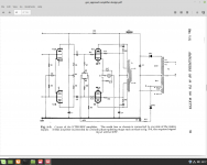
I've used a dual 10k ganged pot as in this circuit attached, this is from the GEC - An Approach to AF Amplifier Design, it's available on the net as a free PDF and has lots of good ideas in it.
Back to the schematic, R8/9 are 10k, R7/10 are 100k and R11 is 10k. R11 is stop bias going to 0v. If you make R8/9 a ganged pot wired so as one pot increases bias, the other decreases bias. To set bias on the amp put your meter on DC V, one lead to output valve V2 g1, the other to OP valve V3. As you adjust the pot the reading will go + 0.1V to -0.1v say, you want to adjust it to 0v if possible, though that's not easy with a one turn pot. To prevent a non bias situation, I used 1m fixed R's from wiper to each end of pot.
Heathkit in their amp use a 300r pot,seems a tad small. The problem with DC bias where no current (or very little) is flowing is that a low value pot gives very little adjustment. I know the pot on the W5M isn't adjusting DC balance but the same applies.
Lastly remember any pot or resistor in the bias circuit may add to the grid leak resistor, which may exceed Rg1 max, you have to be careful what values you use to keep this low.
Cheers, Andy.
Attachments
Think reverse.Not regulating the negative side but the ground solves that problem.jlangholzj,You are right, having the wiper lift open can be a problem.
Mona
Attachments
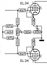
Think reverse.Not regulating the negative side but the ground solves that problem.
Mona
Thanks for the schema, that's the exact implementation I was thinking about. Also FYI for anyone coming across this again, this is the technique I've used when replacing any "tapped" pot when i was talking about using something like virtual CT for heater wires. I hadn't even thought of that when looking at old man leo's schematics.
That's about safe measurement, not a save regulator circuit at all
Mona
Thought this thread was on a pushpull bias balancing circuits???? Am I missing something?
BTW, tubes can pull. Never seen one that could push tho!!
The circuit in #13 is lifted from the GEC book on amplifiers. This one runs straight off the power line. Unless one adds an isolation transformer, in which case a full wave rectifier could be used.
The KT55 is interesting, lots of audio at low voltage. Don't recall it was ever marketed in North America.
The KT55 is interesting, lots of audio at low voltage. Don't recall it was ever marketed in North America.
Attachments
No,Thought this thread was on a pushpull bias balancing circuits???? Am I missing something?
yes Measuring the balance is part of it but a safe circuit too
Depends how you look at it.If a tube pulls convention current it pushes electrons and if pulling electons it pushes holesBTW, tubes can pull. Never seen one that could push tho!!
Mona
- Status
- This old topic is closed. If you want to reopen this topic, contact a moderator using the "Report Post" button.
- Home
- Amplifiers
- Tubes / Valves
- Push-Pull Bias Balancing