Hello,
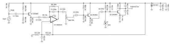
I have built a simple FM transmitter, the FM stage of which is a copy of a very popular diy simple FM transmitter that flows around the net. I attach the schematic of the circuit I built.
My problem is that I can't get it to transmit reliably. After much experimenting with the variable cap, I have managed to sometimes transmit at about 106-107 MHz.
The problem (thus "sometimes transmit") seems to be the antenna to me, but I have little knowledge in RF. Here is the situation I encountered that got me to "blame" the antenna: leaving the circuit alone I would only get hiss at the receiving end (a FM radio), but sometimes, if I approached my hand close to the antenna, I would pick up the clear signal I wanted. So my guess was that my body acted as an antenna etc.
My antenna is a ~21cm long, 22awg insulated solid core wire. Is there a way to determine a proper antenna for this circuit? Or could the malfunction be anything else?
Attachments
It probably drifts so far off tune it is lost. I would use a crystal controlled oscillator and modulate that or use some sort of frequency controlled oscillator.
When I hold my hand close to the antenna, the reception is clear and constant, there is no sudden loss on signal or hiss..
Could this be that my movement resets the frequency of the oscillation because I introduce a stray capacitance, or that my antenna is not sufficient and I boost it with my body?
Of course, I am interested in fixing this circuit for educational purposes... My aim is not building a reliable FM transmitter in general (where I would do what you propose 🙂 ), it is debugging this one!
You're changing the loading of the transmitter's output stage. Try this antenna, it will be a better match.
If that's too difficult, try rabbit ears with a 300/75 transformer, and use RG-59U coax to the transmitter.
Part 15 | Mike Yancey
If that's too difficult, try rabbit ears with a 300/75 transformer, and use RG-59U coax to the transmitter.
Part 15 | Mike Yancey
Last edited:
With a single stage free running oscillator you cannot expect stability - the antenna, your hand - anything - detune the circuit and let it drift uncontrollable. I learned these problems when I fiddled around with fm transmitters as a kid and I can say: This circuit diagram is another useless toy in the wide internet.
Last edited:
What you need is the aerial to match the output impedance of the transmitter -
Aerial Matching.pdf
Loop Antennas and Calculator
I have built many ATU,s for communications receivers as I used both a single ended very long line or a dipole type aerial
Aerial Matching.pdf
Loop Antennas and Calculator
I have built many ATU,s for communications receivers as I used both a single ended very long line or a dipole type aerial
What you are then saying is that the circuit provided by the OP is inherently unstable due ( I take it ) to its simple design ?
To accept that then what you are really saying is the circuit is not TUNED to the FM frequency band ---correct ?
To accept that then what you are really saying is the circuit is not TUNED to the FM frequency band ---correct ?
Transmitter without a modulator. Use an RF transistor and surround mount.
Делаем УКВ ЧМ передатчик на одном транзисторе на обычных деталях с нуля.FM Transmitter. - YouTube
Делаем УКВ ЧМ передатчик на одном транзисторе на обычных деталях с нуля.FM Transmitter. - YouTube
I take it you know a radio transmitter has a "tank circuit " which CAN be tuned to the required frequency.
That being the case the inductance (coil ) and capacitor does the tuning.
That being the case the inductance (coil ) and capacitor does the tuning.
In reality the antenna becomes part of the resonant tank. What you need is decoupling between both. This requires at least a 2-stage design: free-running oscillator driving a buffer driving the antenna. Next step to increase isolation between antenna and resonant tank is a bufferstage that operates on 3rd harmonic of oscillatoer frequency... and so on. Instead of a free running oscillator a quartz stabilized pll is the preferrable solution nowadays
As mentioned adding a buffer to the output should help. However I suspect the output stage does not actually oscillate unless you add the capacitance of your hand. It might be as simple as changing the transistor.
Hello,
I have built a simple FM transmitter, the FM stage of which is a copy of a very popular diy simple FM transmitter that flows around the net. I attach the schematic of the circuit I built.
My problem is that I can't get it to transmit reliably. After much experimenting with the variable cap, I have managed to sometimes transmit at about 106-107 MHz.
The problem (thus "sometimes transmit") seems to be the antenna to me, but I have little knowledge in RF. Here is the situation I encountered that got me to "blame" the antenna: leaving the circuit alone I would only get hiss at the receiving end (a FM radio), but sometimes, if I approached my hand close to the antenna, I would pick up the clear signal I wanted. So my guess was that my body acted as an antenna etc.
My antenna is a ~21cm long, 22awg insulated solid core wire. Is there a way to determine a proper antenna for this circuit? Or could the malfunction be anything else?
FM VCO Transmitter - Electronics-Lab
The 2N3904 isn't a VHF transistor for a start. And we don't know what type the tank
circuit capacitors are nor the Q of the tank inductor.
I found another circuit using 2N2369 which has somewhat more bandwidth and low capacitance, and is probably better suited. Simple FM transmitter circuit based on two transistors.
Note that if you accidentally broadcast in a different band from FM broadcase you are potentially affecting emergency
services, aviation and other important things - unless you have a way to verify the frequency of oscillation you could be
liable to prosecution for this.
Last edited:
Thank you all for your answers.
As I mentioned, I try to find out why this circuit doesn't work, not build a good FM transmitter. I realise this design might be poor (no disrespect for the creator, just the fact that it doesn't appear to be reliably working in every build).
My hand delivering some capacitance to the output stage would be equivalent to throwing some pF's from antenna to ground? This is my understanding.
Another experiment that made it work was touching the circuit's ground to a metal enclosure (guitar pedal), which was earthed (via the amp that was off at the moment). Could this enlighten the problem more?
Antenna and ground are included in the oscillatory circuit and affect the tuning frequency. A body nearby also changes the tuning frequency. Like thereminvox.
This one looks much better. Built into a full metall box this may work well.
As stated before, your antenna is part of the tuning circuit. Modifying the impedance of the antenna changes the frequency. Circuit works as expected. What you can try is to turn the varicap, backoff a few meters, and see if you can find the signal on the FM band. If not, turn the varicap a bit, back off a few meters, etc.repeat. I think this thing transmit on several freq at the same time, this makes it somewhat easy. 🙂 (But it can disturb emergency frequencies!)As I mentioned, I try to find out why this circuit doesn't work, ..
- Home
- Amplifiers
- Solid State
- Simple FM transmitter problem