Hello folks,
I am looking at building a four way mains distribution block and would like to build in DC blocking to see if it will make my transformer in my valve amp buzz a little less.
I have read numerous threads on DC blocking circuits here and elsewhere also and have come across a few examples where contributors have noted that the Diodes or Caps are not correctly orientated.
I have attached the circuit which I was looking at building using two large high ripple electrolytic Caps (KEMET 47,000UF 25V dc 17amp ripple rating) and two diodes (Vishay Fast Recovery 600V 20A, TO220).
I would build one filter which would feed all four sockets. I was thinking of using an aluminium chassis for the sockets, but putting the DC blocking circuit inside a plastic case which would be housed inside the aluminium case.
From my understanding, I think that this circuit is correct and will work but would greatly appreciate any comments to reinforce this (or warn against) before I build anything.
many thanks!
Attachments

Last edited:
I would rather build what is described here: Mains DC and Transformers
From experience, as a start cut a mains lead and wire up a bridge rectifier and caps and run a test if it really does help your issue. If it does get the casing.
There is a good chance it doesn't help anything and then you haven't wasted the time and money on the casing which will probably cost more than the filter inside.
You can mount your transformers on silent blocks and sorting out grounding can also help cut vibration.
It took Elliot a while, but eventually he gets to figure 8 where the correct wiring of the DC block is shown.
Do not use the sch in post1 !
I also recommend a steel canned RF mains filter with an integrated IEC connector socket.
They come in 1A, 3A and 6A versions.
Use the lowest current rating your equipment can manage with.
Do not use a higher current version, since this has less effective interference attenuation.
Do not use a "medical" version, since this omits the "Y" capacitors
Hello and thank you very much for your replies and advice.
I actually already have the aluminium case which was not used from a previous project, I need a few more sockets so will be building the distribution block anyway regardless of the DC blocking or not.
Likewise the 2 Caps and diodes I already had sitting around so if it doesn't help there won't be anything lost financially, just the time spent.
How does the figure 8 schematic improve the circuit versus the one that I have posted that uses two less diodes? Will the circuit I have posted still work? I guess I could source another two of the diodes that I have already and connect them as shown in figure 8.
My Caps are long-life 47,000UF 25vdc 17amp ripple current rated, the diodes are 600V 20amp. Are there any other parameters to consider with these components in this application?
They would be running a valve power amp, preamp and phono stage via the four outlets.
Regarding using a filter on the inlet, I was considering this, I do also have in my parts bin a Class X2 and Y2 cap in delta formation that I could solder across the IEC inlet, it is one of these :
http://uk.rs-online.com/web/p/paper-capacitors/0239668/
To work at it's best, the RF filtering MUST return the common mode interference to the enclosure.
This requires the filtering capacitors to be mounted inside a screening can that is directly connected to the enclosure.
The differential mode interference must be between the two live wires and should preferably be at the input socket.
This is where the integrated IEC socket plus filter inside it's own screening can wins every time. But that can MUST have an ultra low inductance connection to the enclosure. A long PE wire connection satisfies the SAFETY requirement, but does not allow the RF filtering to perform to it's specified curve/values. The metal can must be electrically connected to the enclosure opening through which it passes.
If you add filtering after the IEC socket, then you need an extra can bolted to the enclosure and the cable between the IEC socket and the extra filter also needs to be screened. The screen being connected to the enclosure at BOTH ends.
The same methodology applies to the receiver equipment.
Last edited:
Post1 is inadequate, almost to the point of being wrong....................
How does the figure 8 schematic improve the circuit versus the one that I have posted that uses two less diodes? Will the circuit I have posted still work? I guess I could source another two of the diodes that I have already and connect them as shown in figure 8.......................
It provides only one diode drop (Vf) of blocking and thus less current through the capacitive reactance provided.
In addition the capacitors see reverse voltage on every alternate half cycle.
And worse, are exposed to a high reverse voltage during start up, or during abuse.
Do not build post1 schematic.
Sorry I just re-read your comment in post #4 where you clearly said don't build as per my attachment. Apologies, I completely missed that!
The simplest way forward would then be to source another two diodes and build as per Rod Elliott's figure 8 diagram.
Thanks for your help.
The simplest way forward would then be to source another two diodes and build as per Rod Elliott's figure 8 diagram.
Thanks for your help.
I use 1n5401, or higher.
These pass very high peak one shot transients.
The diodes being in parallel protect each other. The worst case voltage is likely to be <2Vpk, even when 100Apk is passing.
I'm not sure what Vf would apply when a Fault Current in the kA region would induce while the fuse ruptures (in microseconds).
Size the capacitor so that the diodes never turn on for any normal use upto the rated VA of the load.
Start up is a different story and the diodes will pass for a few cycles during the surge event. But they should not get too hot (don't touch them - they are at mains voltage). A soft start will massively reduce the peak start up current.
The diodes may also pass during abusive incidents, but again they should not get hot.
Hi,
Some days ago I started this thread in Audiocircle forums and I advise you to read it carefully.
How to clean the DC at mains. And ripple too
Some days ago I started this thread in Audiocircle forums and I advise you to read it carefully.
How to clean the DC at mains. And ripple too
Size the capacitor so that the diodes never turn on for any normal use upto the rated VA of the load.
Thank you again for your help, but I am not sure I understand how to apply this and size the capacitor appropriately in the application of the figure 8 Rod Elliott circuit.
I have two of these Caps (47,000UF 25vdc 17amp ripple):
ALS31A473DF025 | KEMET Aluminium Electrolytic Capacitor 47000μF 25V dc 36mm ALS31 Series +85degC | KEMET
Ideally I would like to use them if this is feasible and safe in the figure 8 circuit.
Would the above caps be appropriate for use with four of the following diodes? (I have four of these diodes already, I just found another two)
(Fast recovery, max forward current 20Amp, peak reverse voltage 600v,
max forward drop 1.3v)
VS-20ETF06-M3 | Vishay VS-20ETF06-M3 Fast Recovery Diode, 600V 20A, 2-Pin TO-220AC | Vishay
Hi,
Some days ago I started this thread in Audiocircle forums and I advise you to read it carefully.
How to clean the DC at mains. And ripple too
Thanks I shall have a read. I am hoping however that I can use the parts that I already have in hand if at all possible and of course safe.
This looks like you are throwing money at the solution rather than building it to perform adequately.Thank you again for your help, but I am not sure I understand how to apply this and size the capacitor appropriately in the application of the figure 8 Rod Elliott circuit.
I have two of these Caps (47,000UF 25vdc 17amp ripple):
ALS31A473DF025 | KEMET Aluminium Electrolytic Capacitor 47000μF 25V dc 36mm ALS31 Series +85degC | KEMET
Ideally I would like to use them if this is feasible and safe in the figure 8 circuit.
Would the above caps be appropriate for use with four of the following diodes? (I have four of these diodes already, I just found another two)
(Fast recovery, max forward current 20Amp, peak reverse voltage 600v,
max forward drop 1.3v)
VS-20ETF06-M3 | Vishay VS-20ETF06-M3 Fast Recovery Diode, 600V 20A, 2-Pin TO-220AC | Vishay
Don't waste that 25Vdc capacitor where a 6V or 10V capacitor would do perfectly adequately.
Why use a low Vf expensive rectifier diode when a 1n5401 will do the job?
yes I think that you are right that it is perhaps a waste of these caps and diodes which are more than what is required. They have been lying around for a while however so I would rather use these than purchase more parts as it seems unlikely I will get around to using them elsewhere, especially the Caps.
I had thought it a safer bet, in this application to use larger caps, with a longer life and over-rated ripple current rating.
I had thought it a safer bet, in this application to use larger caps, with a longer life and over-rated ripple current rating.
I would use 25V caps, but not ones that big and expensive. A pair (or quad) of 4700uf 25v snap-in caps are probably fine. As well as 1N5404 diodes - or at most 6A04's. Unless you plan on cranking it up to war volume often. In that case you wont hear the transformer buzz.
DC Scraper kit for the GT-102 (NODC) - $24.95
Akitika Store
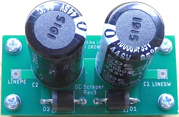
[ You can install the DC scraper kit to quiet the buzz. It works by removing the DC component of the input power, leaving just the AC that all transformers love. So, even if your neighbors (or you yourself) have a heat pump or air-conditioner that draws nasty asymmetric currents when it runs, you can Scrape away all the DC, and keep your transformer quiet... ]
[PDF] https://www.akitika.com/documents/DCScraperAssemblyManualRev1p02.pdf
YouTube DC Scraper Kit for the GT-102 Nullifies the Effect of Asymmetric Power
Akitika Store
[ You can install the DC scraper kit to quiet the buzz. It works by removing the DC component of the input power, leaving just the AC that all transformers love. So, even if your neighbors (or you yourself) have a heat pump or air-conditioner that draws nasty asymmetric currents when it runs, you can Scrape away all the DC, and keep your transformer quiet... ]
[PDF] https://www.akitika.com/documents/DCScraperAssemblyManualRev1p02.pdf
YouTube DC Scraper Kit for the GT-102 Nullifies the Effect of Asymmetric Power
- Home
- Amplifiers
- Power Supplies
- Mains distribution block with DC blocking