
I've never seen anyone connect the suppressor grid to the Anode
I have seen the screen grid used as a second control grid in a mixer tube like the 6888, but the suppressor grid is still connected to the Cathode.
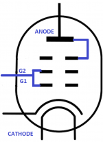
Standard Triode Mode:
Connect the suppressor grid (Top Grid) to the Cathode.
The Screen grid (Middle Grid G2) to the Anode.
Control Grid (Bottom Grid G3) is the input.
I have seen the screen grid used as a second control grid in a mixer tube like the 6888, but the suppressor grid is still connected to the Cathode.
Standard Triode Mode:
Connect the suppressor grid (Top Grid) to the Cathode.
The Screen grid (Middle Grid G2) to the Anode.
Control Grid (Bottom Grid G3) is the input.
Last edited:
Tying g1 and g2 will profoundly change triode characteristics compared to conventional g2 to plate strapping. See for example the 46 triode data sheet.
Suppressor grid: In the pentode valve / vacuum tube, the suppressor grid is generally maintained at a low voltage, often connected directly to the cathode. Its function is to create a lower voltage region between the screen grid and the anode. It suppresses the secondary emission where high energy electrons hitting the anode at high speed have a tendency to bounce off. This effect causes a kink in the response curve of tetrode valves. In this way it enables the pentode to provide a high amplification factor along with the ability to operate at high frequencies.
In all my years working on tube/valve equipment I have never seen or heard anybody doing this.
In all my years working on tube/valve equipment I have never seen or heard anybody doing this.
The Randal Amplifier Project in San Francisco, CA used EL34 tubes.
The Suppressor, and Screen grids were both tied to the Plate.
The Suppressor, and Screen grids were both tied to the Plate.
Never heard of it in the UK.
If the purpose of the Suppressor grid is to control secondary emissions (electron flow) from reaching the cathode can you explain the "advantages" of doing this ?
If the purpose of the Suppressor grid is to control secondary emissions (electron flow) from reaching the cathode can you explain the "advantages" of doing this ?
Last edited:
Hold on--- Randal is a guitar amplifier maker -now I get it --distortion welcomed and yes I do like Jimi Hendrix .
It is possible to connect g3 to the anode.
If it has any advantage for this type?
Pentodes connected as triodes
If it has any advantage for this type?
Pentodes connected as triodes
In no case uses the graphic connection.
G1 and G2 like control grid, and grid 3 and anode tie together ..
Valve 46 as Mr. 6A3sUMMER says has double grid, and G2 work with Plate, or work like second control grid .. both with astonishing results.
G1 and G2 like control grid, and grid 3 and anode tie together ..
Valve 46 as Mr. 6A3sUMMER says has double grid, and G2 work with Plate, or work like second control grid .. both with astonishing results.
The thing is most (all?) pentodes with internally connected suppressor grid have it connected to the cathode. It is beneficial for pentode mode operation.
That's probably the reason why people don't even think about connecting it differently.
But connecting the suppressor grid to the plate is beneficial for triode mode operation.
"Plate" resistance becomes lower, linearity becomes better. The amount of needed bias voltage and the Miller capacitance both raise though.
The only thing you have to be careful about is the g3 ratings (both power and current) - some tubes have pretty whimpy suppressor grid.
GU-50 doesn't.
Do it.
Here are the FU-50 (Chinese GU-50 clone) plate curves for both types of connection. See for yourself. Disregard the lower power dissipation rating with g3 connected to the plate - FU-50 does have whimpy suppressor grid. GU-50 doesn't - you can safely go for the full 40W "plate" dissipation.
I am talking of the suppressor grid NOT the screen grid , I know all about G2 connected to the Anode , done it myself but as some here seem to think it "improves " the sound then I require a proper scientific statement referring to manufacturers specification on tube/valve technology.
I will accept Mullard -Philips -Osram-Brimar- RCA -Madza-Tungsram-Marconi-GEC official company documentation.
I will accept Mullard -Philips -Osram-Brimar- RCA -Madza-Tungsram-Marconi-GEC official company documentation.
The best inclusion of the GU 50 and LS50 for audio is to connect the first and second grid together. Then you get a triode with the right characteristic exactly like RCA811A, Г-811.
http://www.r-type.org/pdfs/ls50.pdf
http://www.triodeel.com/gothamp.gif
811a Opt
YouTube
http://www.r-type.org/pdfs/ls50.pdf
http://www.triodeel.com/gothamp.gif
811a Opt
YouTube
Last edited:
I am talking of the suppressor grid NOT the screen grid , I know all about G2 connected to the Anode , done it myself but as some here seem to think it "improves " the sound then I require a proper scientific statement referring to manufacturers specification on tube/valve technology.
I will accept Mullard -Philips -Osram-Brimar- RCA -Madza-Tungsram-Marconi-GEC official company documentation.
Option 1 explodes.
Option 2 does not explode and its sound is bad.
Option 3 does not explode and its sound is normal expected.
Option 4 does not explode and its sound exceeds expectations.
It is worth the game.
Attachments
There is a commercial Randal guitar amp, OK.
But I am talking about the Randal amplifier project from about 25 years ago.
It was a Hi Fi teaching project amplifier. That is completely different.
I was not on that project.
You have to query them if you want the "why do it that way/"
But I am talking about the Randal amplifier project from about 25 years ago.
It was a Hi Fi teaching project amplifier. That is completely different.
I was not on that project.
You have to query them if you want the "why do it that way/"
So nobody knows the result of connecting G1 and G2 together ,and G3 and anode together in a GU50 tube ?
The best way to find out how well it works is to do your own circuit.
Are you really planning to build an amp like that?
You may choose to bias it differently, use different B+, set to a different current, use a different load, etc. versus what anybody did before.
Or do it exactly like they did it, and when you have it up and running, then change the G3 connection.
Just do it by tying the Suppressor to the plate through a low wattage resistor for safety (in case the suppressor shorts to another element when it swings through the range of plate signal voltages).
Please let us know how it comes out.
Last edited:
Option 1 explodes.
Option 2 does not explode and its sound is bad.
Option 3 does not explode and its sound is normal expected.
Option 4 does not explode and its sound exceeds expectations.
It is worth the game.
I know where you got that picture but it is not from any past recognized tube manufacturers manual issued by those manufacturers to help tube design engineers .
I have many of their professional manuals as I applied to the head offices of their companies for them at the time running through the Mullard one there is no sign of official recognition of this method .
Now this being 2020 and most posters on tube technology still use old designs to achieve high quality sound the relevance of those old manufacturers manuals still applies as they detail many aspects of the companies tube designs .
Can you supply a large modern manufacturer of tubes recognized by the world as producing high quality tubes who both show and recommend this engineering method ?
GU50 is a beam pentode. those. the screen grid is in the shadow of the first grid in other words the step and the number of turns of the first and second grid coincide. The third grid is wound as usual with pentodes. The anode is very far from all grids. You do not need to connect a third grid to the anode. In this case, a part of the anode current will flow through the third grid, and the grid itself is quite thin and weak. You can’t win anything from such an incorrect connection, you’ll only lose.So nobody knows the result of connecting G1 and G2 together ,and G3 and anode together in a GU50 tube ?
Last edited:
I was surprised to see the document posting where it showed that the Suppressor could be connected to the Anode. It seems we have some contradiction with the experts on this forum and no documentation on the configuration you propose. The supporting document posted shows the screen and suppressor connected to the Anode, which would not create the power stress differential on the suppressor that connecting it to the anode alone without the screen would create. The bottom line IMO is this:
(You can't win anything from such an incorrect connection, you'll only lose - GUNFU).
In all the thousands of Pentode tubes manufactured not a single one was designed with this intention. Not even in the few where the Suppressor grid was designed with a higher power dissipation. It in fact defies the very physics for creating a Pentode in the first place.
I think it would make more sense, if you intend to try the connections as you posted in the OP, you just tie G1 and G2 together and leave G3 with NC, (Can that work?) or since this tube's Suppressor handles more power than most, connect all three grids together. If it were me, I would use the conventional triode mode pentode configuration.
Last edited:
- Home
- Amplifiers
- Tubes / Valves
- GU50 amp triode mode single end