DIY cheap Bench Power Supply 45V 3A

I made a couple of cheap Bench PS myself from components from Aliexpress. Total price is around 60-70eur for both. I often need a single or dual PS for testing various DIY devices. The concept is an AC/DC fixed power supply 48V 4A, then a noise filter 50V 4A, then an adjustable DC/DC step down power supply (with a current limit) of 50V 5A and again a noise filter 50V 4A. The devices are not grounded to IEC, so I could make dual power supplies up to +-45V. Realistic possibilities are approximately 45V and 3A. Plastic box - 160x160x65mm.
Links:
https://www.aliexpress.com/item/4000287613667.html
https://www.aliexpress.com/item/1005005396072901.html
https://www.aliexpress.com/item/1005007948946980.html
https://www.aliexpress.com/item/4001224998003.html
https://www.aliexpress.com/item/1005003597145707.html

Attachments

  • BPS1.jpg
    BPS1.jpg
    380 KB · Views: 129
  • BPS2.jpg
    BPS2.jpg
    356.3 KB · Views: 126
  • BPS3.jpg
    BPS3.jpg
    318.9 KB · Views: 114
  • BPS4.jpg
    BPS4.jpg
    329.8 KB · Views: 117
  • BPS5.jpg
    BPS5.jpg
    243.4 KB · Views: 122

UNSET Power Head V1.2

I am coming to the end of a long build that ended up being 90% in the presentation, mainly because I hamstrung myself by aiming for a small footprint.

Anyway, now I am looking for something where the tube electronics take the forefront, so I have dusted a pair of UNSET Power Head (UPH) boards I bought last year.

Below is a mapping of the parts numbers on the UPH board to the original Unset BOM in the first post of that thread.

Next I looked at sourcing the PFET, FQPF9P25 or FQAF9P25, which has become obsolete, as mentioned by George in 2023.

Is this one a suitable replacement? IRFI9634G
CRSS is 40pF instead of 27pF, and that is cited as being a key parameter on the UNSET thread, but looking at other posts on other threads, the suggestions there are normally worse than this. The gate-source threshold voltage is 4V instead of 5V, and the max current rating is 4.1A instead of 6A, but otherwise looks to be similar to FQPF9P25.


1735901717861.png

Tweeter Protection

Hi I need a bit of advice I've tested my speakers that have been in storage for 15yrs at very low volume & sounded OK before ordering my 4 channel Hifiberry Beocreate 4 amp with dsp & UMIK-1 for measuring all new to me need some advice on capacitors to protect the tweeters so I can play around with the software I pick things up quicker practically once I get the hang of things even hopefully upgrade drivers in cabinets I've uploaded Data Sheets of drivers after checking the part numbers I've had them from New thanks for any help

Attachments

Greetings from Italy

Hi team - I am a seasoned engineer and musician, who recently decided to pivot towards building, instead of just buying. I am in the process of building my own stereo system (emphasis on "stereo", no home theatre, no surround, no Atmos, just old fashioned two-channel music), with a mix of professional, home-built and consumer equipment. I'll be glad to partecipate, learn and contribute.

Power amp question

Hi,
I would like to ask you a question, also at the risk of it being a stupid question :yes:
After almost 30 years of doing nothing, now I've finished my two ACAs. And they are great. But - the diy-fever is here and I want more. One thing is certain: the next project must be another Pass power amp... but which one 😕 So here it comes, the stupid question: is there a "ranking" of the power amps? Is an F6 better than an F5 better than an Aleph J better than an M2x... and so on? They are all great, but are they only different at the same high level of the sound quality (what comes first for me)?
Thank you for your help in making a decision 🙂

Cheers

Is there a way to electrically verify good and genuine chip? LM3886

Without put them in circuit and measure result, of course!

I was wondering about how to check authenticity of the chip. I got a numbers of chip when it was scarce from various dealers. Just want to check them before putting them in my next project. Apart from buying from reputable dealers and obvious dodgy looking chips, I have seen very convincing laser-engraving counterfeit chips/parts that often work but might not up to spec of authentic chip.

As a result, I thought that maybe we can measure resistance or using diode function or other measurement from basic DMM or oscilloscope to measure them? For instance, TI publishes equivalent schematic and shown BJC power transistors between output (pin 3) and V+ (pin 1, 5) and V- (pin 4), so I should expect measuring between base, emitter and .45 ohm resistors between pin 3, 1 and 3, 4? Additionally, input transistors could be measure at pin 9, 10 and V+ (base and collector)? They should have similar result?

Additionally, measuring resistance between power supply pins and ground (pin 7) should yield reasonable results, but what are ranges of reasonable result should I expecting?

Thanks for your comment.
AP

Elevated heaters - coupling from cathodes into heater supply?

Hi! When I use dc heater supplies (say in phono stages) I usually elevate the heaters above cathode potential. As I understand it there can't be a flow of electrons from the heaters at a potential positive to the cathode and no potential hum couples from the heaters into the signal. But what happens now is that the signal on the cathode couples into the heaters, right? Or does the cathode resistor bypass C provide a lower impedance path to ground and this wouldn't happen?
And if it happened could it be an issue of some kind? Say e.g. in a stereo amplifier with parallel wired heaters would it have a negative influence on channel separation?
Thank you for your thoughts and maybe even experiences.

For Sale Old Catalogs/Manuals for sale Cheap!

Have a lot of old catalogs, manuals, tube reference material, etc. Been collecting for over 35 plus years and this is what is left. There is a few items on Mac stuff, tube amps and preamps, etc. Also Hi Fi Spotters guide 1&2...Wish to sell the entire lot. Would like to get $20.00 for the lot. Comes out to about 10 pounds of stuff. Shipping should be about $15 bucks... Hope someone still collects this stuff. I accept PP as F&F or postal MO... U.S sales only.

Attachments

  • MVC-001F.JPG
    MVC-001F.JPG
    82.6 KB · Views: 51
  • MVC-002F.JPG
    MVC-002F.JPG
    68.9 KB · Views: 42
  • MVC-003F.JPG
    MVC-003F.JPG
    54.3 KB · Views: 48
  • MVC-004F.JPG
    MVC-004F.JPG
    49.6 KB · Views: 44
  • MVC-005F.JPG
    MVC-005F.JPG
    53.9 KB · Views: 47
  • MVC-006F.JPG
    MVC-006F.JPG
    72 KB · Views: 48

Lurking in SoCal

Long time Tube guy who stepped it up a notch when I got involved
with Don Garber's gear. (421a, EVO pre and Super X).
Not a DIYer, but have recently come into possession of an EleKit 8550,
built by (Paul?) at Tubes4HiFi, (mine is pictured on P. 4 of VKmusic's
8550 thread) that led to the purchase of a SUNVALLEY s1645D from
Victor, nothing but good things to say about Victor's service!
  • Like
Reactions: 6L6

Mistakes We've Made

Hey let's be honest, we all make mistakes. Some are pretty dumb. And when you get into the audio world, dumb mistakes can be costly.
Just yesterday I was playing my Kenwood KA-7100 and moved my speakers while it was playing and shorted something out. So dumb 🙄. (Taking donations on that repair. 😉)
So anyway, maybe you all could share some mistake you've made, especially in the audio world. The more costly the repair, the more interesting it will be. Thought it might be interesting for us all.

2SK880-GR model

Hello guys,
I just wanted to share roughly made SPICE model of 2SK880-GR n-channel JFET I just made.
Enjoy!
O.

.MODEL 2SK880-GR NJF(
+Beta=30m
+Betatce=-.5
+Rd=19
+Rs=19
+Lambda=32m
+Vto=-500m
+Vtotc=-2.5m
+Is=10f
+Isr=1p
+N=1
+Nr=2
+Xti=3
+Alpha=10u
+Vk=10
+Cgd=7.3p
+M=.3622
+Pb=3.2
+Fc=50m
+Cgs=11.5p
+Kf=.001f
+Af=500m
+mfg=Toshiba)
  • Like
Reactions: Salas

Please help me understand ribbon/planar phase alignments

I'm having trouble with crossing this ribbon (GRS RT1.R) with this planar mid (GRS PT6825-8). I can cross them anywhere from 2k-8k and there ends up being a dip in response immediately once you go off axis even a few degrees. How can this be? I've modified my XO to be nearly all 4th order filters to try to keep them in phase. If I go any less, even a 3rd order, they will be in phase at the XO and then a few thousand hz later they will be out of phase and cancelling out. The same thing seems to happen to the mid and woofer crossover. The woofer is just a cone woofer. It is far less pronounced with the mid to woofer than with the mid to ribbon XO. I am not understanding how this can be.

Is this just the nature of ribbons and planar?

I managed to get the woofer and planar XO halfway decent.

This is designed to be listened to at a desk so it isn't that horrible of an issue but I would like to understand it.

The drivers are not vertically aligned. Here is what the unit looks like. I have entered the offset data into the XO. Even if I removed the X axis offset from the data. Essentially making them vertically aligned, it makes little difference.
1737905219010.png


Here is the current XO. You can see how big of dip there is at even just the 15 degree mark
1737905266543.png

Then here are the responses of the tweeter, mid, and woofer respectively. Notice how crazy these responses on. I had to hammer these things into shape to get anything like an accurate response.

Woofer
1737905359675.png


Mid
1737905397006.png


Tweeter
1737905418209.png


I took these measurements with a jig so that the microphone was positioned exactly at the front of each driver when taking the measurement. It was aligned with the face of the unit so that the Z offset would be taken with the data.
1737905599063.png


I'm sure there is just something I do not understand here. If anyone knows, please let me know. Possibly its just hard using these types of drivers. That I can accept as I didn't think this would be easy. Odd parts cause odd issues.

Lastly, someone mentioned to me to hit ctrl+alt+E to fix phase issues in REW. Does anyone know exactly what this does? It seems to affect the delay. Wouldn't this throw off my Z offset data that would be inherent to the measurement?
1737905744219.png


As always, thanks for reading. Any and all responses will be read and appreciated.

Replacing NHT XDS Seas tweeter possible?

Mine are labeled "050/1 1201 Norway". You can see them in a photo of a disassembled XDS at Audioholics:

https://www.audioholics.com/soundba...nht-xd-loudspeaker-system-review/Graphic5.jpg
https://www.audioholics.com/soundba...nht-xd-loudspeaker-system-review/Graphic6.jpg

Full review:

https://www.audioholics.com/soundbar-and-satellite-speaker-reviews/nht-xd-loudspeaker-system-review

I don't need exactly what the XDA processor expects as I'm doing the digital crossovers in software.

Feedback-Based 6N3P-E Preamp

I'm busy working on a layout (just one tube) for a 6N3P-E based hybrid preamp with feedback (horrors!), run by a little Antek toroid with a 150V HV regulator of my own design using a 500V p-channel mosfet I nabbed from Electronic Goldmine. I'll be using the ZVP2120GTA p-channel mosfet (SOT-223 SM package) from Diodes, Inc., as it has lower gate capacitance than the IRF9610 mosfets originally used in the design (zippier performance). Details will follow as I get the design worked out.

I originally posted this as an aside in the Salas 6V6 preamp thread, but the project has since acquired a life of its own, hence the separate thread.

Featherweight Title Fight

Can anyone figure out what's going on in the Danley CS-30? I can't figure out how they're getting a bandpass-ish response curve along with an impedance curve that almost looks like a sealed box.

Based on some comments from Ivan Beaver, it looks like the CS-30 complements the TH-Mini well, so I thought I'd pit them head-to-head.

(According to Beaver, the CS-30 digs deeper at the cost of low frequency efficiency, but the Mini has higher efficiency *and* higher power handling than the TH-Mini in the octave from 40 to 80hz.)

Comments here:

zmarchive.com psw-srf: 35103 Mini Subs

Yamaha MX-600 Amp will not come out of protection. Should protection circuit be rebuilt.. Outputs out of circuit and still in protection.

Hey, have Yamaha MX-600 stuck in protection mode. All outputs are out of circuit and still in protect mode.. What to check next or just rebuild protection circuit. Relay has been replaced and + and - voltages coming off of bridge to main caps..
Input greatly appreciated

MarkAudio CHP90 Full Range Bass Reflex Monitor, Passive Crossover Response Help

Hi all,

I built a fun speaker a while back based on the Mark Audio CHP90 in a bass reflex design using some big oak slab baffles. Very rustic chic. I've been using active DSP on them to handle any issues from the overall baffle changing the response. I recently took them outside to do some measurements to get a better pseudo-anechoic response so that I could export it as an in-baffle FRD and used my DATS to generate a ZMA from in-baffle as well. The goal being to take these measurements of the driver in the cabinet and work on them in VituixCAD to alter the frequency response a bit in a passive crossover, even though its not really crossing over.

I'm attaching my VituixCAD file for anyone that wants to play with it to help out (renamed to *.txt, just remove the .txt and it will be good to go)

Overall I'm just trying to flatten it a bit. Doesn't have to be a heavy natural house curve, but just flattening it would be a nice thing for me. I don't particularly want to make $100 crossovers for this, but I'm just seeing what I can do and what I can tolerate with some basic passive components. Any advice or criticism is appreciated!

DSCF1429.jpg


20241204_132214.jpg


20241204_132327.jpg


20241204_133044.jpg


I did farfield impulse response gated measurement of the driver, and then did near field of the driver and port and scaled the port's output via area and then summed the near field response. Then I corrected it for the baffle to full space. Final measurement:

As you can see there are a few big spikes I'm trying to potentially tame down, and then maybe lower the upper end in general to flatten it out. Those spikes are around 4200hz, 6400hz and 11800hz.

I used this measurement to generate an in-baffle FRD.

CHP90 In Baffle Fully Corrected Anechoic Response.jpg


I used this DATS measurement in-baffle for producing the ZMA.

CHP90 Port Tuning Left.jpg


I'm currently working in VituixCAD. A few options, the response on its own and some of my efforts so far.

RAW response in VituixCAD with no components:

1733451390318.png


Here's one approach I'm looking at:

1733451431291.png


1733451439917.png


And then I went overboard with notch filters to hit those 3 spikes. Overall this seems silly and wasteful. Maybe there's a better way? Looking for advice on that.

1733451478047.png


1733451489869.png


Any suggestions appreciated!

Very best,

Attachments

Peerless K040MRF mf driver replacement

Any suggestions where I can get a replacement for a Peerless K040MRF medium frequency driver or what drivers I could use in place of a damaged unit. It looks like this.
Peerless K040MRF a.JPG - Peerless K040MRF b.JPG
I can't find one on Ebay in the UK. It is in a Pro9TL Mk2 cabinet and has failed completely. This thing has a sort of a can on the back of it so doesn't depend on an enclosure which makes replacement difficult.

15" Woofer suggestions for End-Game 3-Way?

Hi DIYers,

After a few difficult years with the further realization of how short life is, and that it can be forever changed in a day, I've been led to a place where I feel if I'm going to achieve life's little goals, now is the time. One goal is a dream speaker, a 3-way of the highest resolution and sound quality, along with good aesthetics, to rival $100,000 high-end speakers. This is not a "no-compromise" speaker, as every decision is a compromise in some manner. Speakers will be used for everything from orchestral, classical, acoustic, pop, movies, and video games in a residential system.

I implore people to recommend 15" woofers, and interesting 12” woofers are also considered, as there is no possibility of hearing these locally. I have mostly been looking at big radiating area, because I like the way they present recorded elements as room-filling and life sized. I also consider myself among a smaller number of listeners that prefer an over-damped, fully stuffed cabinet. My current speakers are Yamaha NS-1000M and Quad ESL-989 electrostatics, and I would like the future speaker to share the high-resolution traits these provide, but with more extension and sensitivity similar to the NS-1000M.

Some drivers I have modeled include a small number from from TAD, Acoustic Elegance, B&C, BMS, LaVoce, Eighteen Sound, Audio Technology.


The bass parameters can be changed as the physics require, but mostly center around the following:

  • Low-pass crossover point of 450Hz, depending on mid might be 250Hz.
  • 8-Ohms nominal impedance.
  • About 94dB sensitivity at 1W. System goal is +88dB after baffle step compensation.
  • Aperiodic or Sealed enclosure, 100 liters target. 150L max, as it the bracing and curved wall thickness makes the speaker large.
  • Enough extension to not need a subwoofer. This one is sometimes at odds with sensitivity and enclosure volume.
  • Rolled or accordion suspension are welcome for longevity. Ribbed paper cones are great.
  • 100W power input handling.
  • Will be used with solid-state amplification.

Audio Card in Linux

Hello.
I register here, because i have a problem with an Audio Card.

Is there a Linux distro in which the APS (Audio Production Studio audio card, by EMU) is working "out of the box" ?
I have test it in AVLinux MX 19.4 (for 32 bit) and it is not working.
Or if there is not, then does somebody know a patch or a setting or something.., that will make it give sound ?
I have tested, in the same distro, two other cards with the same processor (EMU10K1) and they work "out of the box".
Thanks

Replacement volume pot for Marantz 7C

I used a 500k dual gang PEC carbon pot for my Marantz 7C copy build but unfortunately, as I had heard others warn about, the tracking of the two tracks is off quite a bit and requires rebalancing every time I reduce volume any where near 1/4 turn or lower.

I noticed that Parts Express and some other suppliers I've used in the past does not carry anything over 250K in an Alps stereo pots which I wanted to try. Any suggestions for another brand that is good enough for the task in a reasonable price range. I guess the next question for anyone versed in old tube designs such as the Marantz 7C, would a 250K pot work for the task or would it cause any impedance mismatching enough to avoid?

HK 3490 failure

For a friend I am repairing a Harman Kardon HK3490 receiver. One of the channels was dead. After checking the output stage both output transistors, the bias transistor, a safety circuit resistor R362 and one half of the current limiting resistor R356 are broken. I have found and installed replacements but are still waiting for R356.
Does anyone have an idea what could have caused such a pretty big failure? The power supply is ok and the other channel is working. All the other transistors measure ok.

HK3490_PowerAmp.png
  • Like
Reactions: kikoguerra

LS165w-2T noise reduction

A LS165w-2T is an SMPS producing 300v @ 0.3A and 6.3v @ 5A. It's available at AliExpress and is inexpensive and small. There is a review at another forum at
https://www.head-fi.org/threads/review-ls165w-2t-switch-mode-power-supply-for-tube-amp-use.975587/

Would one or more of the experts on this forum be interested in creating something similar to AmyAlice or PO89ZB that could reduce the noise in the 300v output?

If there is already such a circuit, could you let me know where it is?

ray

Hello, my name is Augusto from Brazil. i have a harman kardon HK 3490 with sound problem. Thanks!

My HK 3490 device is very well preserved and has very little use, but it has a significant hissing sound in the left channel. Here in Brazil I do not have assistance or technicians with experience with these devices, so if anyone has had this problem and can give me some suggestions, I would be very grateful.

DIY soundcard intended for measuring amplifiers

I've been working on this for about a year and still incomplete but almost done. I couldn't hold myself to post some first pics.


Actually, it has been quite some time I'm fooling around low cost soundcards trying to modify them for improved performance. What strikes me is that although manufacturers don't hesitate to use top class chips, the overall performance is compromised by design. For example the power supply even if it's not the USB Vbus, it will be just a small external wall wart. Another problem is the necessity for a user friendly front panel which leads to a messy PCB layout. And then it comes the copyright war forcing companies to adopt proprietary solutions especially in the software domain, causing even instability issues in some cases. Most of the time I came to think what if app notes were followed to the letter but this would take a complete redesign from scratch. Eventually it happened.🙂


I rush to catch up any queries. This is not meant to be a giant killer. In fact, I deliberately stayed within limited bandwidth and dynamic range to avoid meeting spooky shadows. The target was the low to mid cost commercial soundcards. That said, it costs more than a Focusrite Scarlet to build 😱 and one might think that it doesn't manage any better. But all these products need some kind of input protection and usually adding that will also add THD+N. So, my soundcard is ready to accept an amplifiers output, the loop measurement are taken on these inputs and the total cost is much less than a soundcard-input interface combo.:up: And it's mine, which is priceless...


About specifications: Two channels -stereo- full balanced I/O. Input impedance 100k. Input sensitivity for 0dBFS 1,5Vrms differential. Input protection for 400VDC. Also it should be OK for 100Vp AC but I haven't tested that. Output can drive most usual loads with a max 2,6Vrms differential. Full duplex up to 192kHz/24bit, but usable only at 48kHz with ARTA, REW and the alike.


Still on the bench, I expect a little more improvement when I put it in the box. I verified that at least for the 50Hz noise. Lock down delays but it shouldn't take long more. I'll share all schematics and gerber files for anyone who needs something like that and can build it.

Attachments

  • I.JPG
    I.JPG
    81.4 KB · Views: 1,328
  • II.JPG
    II.JPG
    64.4 KB · Views: 1,368
  • III.JPG
    III.JPG
    194.3 KB · Views: 1,361
  • IV.JPG
    IV.JPG
    238.8 KB · Views: 1,343
  • Like
Reactions: geraldfryjr

B&O MMC4 - Stylus repair (help needed)

Hi, i have an mmc4 stylus which had one channel not working/had very very low output. Since I’m too curious not to, I thought f*** it and opened it up.

Can anyone suggest how it is supposed to work?
I can’t find resources/ drawings or anything about the “wiring” of the coils.

After extracting the coils i noticed that part of one had become loose/ potentially even has a break in the wire except its so tiny i’ll need to get a magnifying glass.

Any advice on how to do surgery on it (if its even possible)?

Attachments

  • 5434CB8A-CAC7-439B-8A88-E40C226B4922.jpeg
    5434CB8A-CAC7-439B-8A88-E40C226B4922.jpeg
    255.5 KB · Views: 130
  • 427252CB-A28F-4A2C-8297-37B563569B36.jpeg
    427252CB-A28F-4A2C-8297-37B563569B36.jpeg
    353 KB · Views: 119
  • 2EF67DB1-6034-41B3-A8CF-7C36CDF23483.jpeg
    2EF67DB1-6034-41B3-A8CF-7C36CDF23483.jpeg
    309.2 KB · Views: 100

For Sale Audioamp.eu Automatic Bias Control for 4 Tubes

Audioamp.eu ABF-Q Auto Bias For 4 Tubes With Filament Transformer

I bought 2 of these a few years ago and this one didn't get used.

The ABF-Q module from Audioamp.eu is an automatic bias control system designed for tube amplifiers with four output tubes, configured in push-pull (PP) or parallel push-pull (PPP) arrangements. It ensures optimal performance by dynamically adjusting the bias of each tube, maintaining strict current symmetry between the output stage branches, and preventing DC current flow through the output transformer. This approach minimizes low-frequency distortion and extends tube lifespan.

A notable feature of the ABF-Q is its integrated 6.3VAC isolation transformer, making it suitable for amplifiers where the 6.3 VAC filament supply is referenced to ground.

Sold

Attachments

  • IMG_9471.jpeg
    IMG_9471.jpeg
    1.2 MB · Views: 47
  • IMG_9469.jpeg
    IMG_9469.jpeg
    1,018.7 KB · Views: 47
  • IMG_9470.jpeg
    IMG_9470.jpeg
    1.1 MB · Views: 40
  • IMG_9472.jpeg
    IMG_9472.jpeg
    917.2 KB · Views: 48

Introduction from St. Louis

New member from St. Louis. I like to build audio stuff. I have built a number of speakers: Linkwitz Plutos, Linkwitz LX-Minis, Linkwitz LX521.4s, CSS Criton, GR Research X-Statics, etc.
I built the LX-Mini analogue crossover, but it does not work. I came here for looking for help with that.
I am about to build the Amp Camp amp.
I own some vintage audio equipment such as Great American Sound amps, a Conrad Johnson preamp, Denon and Technics turntables, etc. Looking forward to the expertise of this group. I am sure I will learn a lot.

John

Fostex T90A L-Pad/Crossover Enclosures

Bought these from Reallygoodstuffs.com for $350 and they work great! I only ever ended up using them at full volume in my system so I am selling them and just going to a cap. These have the Solen 1.5uF installed and ready to plug & play.

More info here: https://reallygoodstuffs.com/L-PAD Enclosure.htm

Asking $200 plus shipping

Attachments

  • IMG_5128.JPG
    IMG_5128.JPG
    443.5 KB · Views: 52
  • IMG_5129.JPG
    IMG_5129.JPG
    594.7 KB · Views: 50

Modushop chassis punch design library

I was wondering if there is any support for establishing a “library” on DIYAudio consisting of different designs for custom punch/machining patters (in DWG format) for front and rear panels of various Modushop chassis?

For example patterns developed and actually used by members could be posted in an organized fashion, perhaps by chassis type, size, and application (e.g., generic preamplifier, ACP+, H2). Each design would be accompanied by a short description, e.g. 2 RCA input in 1/2” hole; 2 XLR D/size outputs, and so forth. One could then open files to see if configuration meets their needs and then submit them to Modushop rather than possibly incurring a drafting fee.

I’d be willing to work on this if there was interest and support from DIY Audio.

Modulus 86 Amplifier

Here is a DIY Modulus 86 amplifier with dual mono SMPS power supplies. The boards, and inductors were all purchased from Tom's website, the chassis is a Modushop Dissipante and the rest DigiKey/Mouser. The amp sounds great! See Tom's site for more info: https://neurochrome.com/products/modulus-86

Asking $400 to your door in CONUS

NOTE: The hole on the IEC and power switch are elongated since I mis-measured the height! 🤦‍♂️

Attachments

  • mod1.jpg
    mod1.jpg
    86.9 KB · Views: 237
  • mod2.jpg
    mod2.jpg
    86.3 KB · Views: 191
  • mod3.jpg
    mod3.jpg
    74.2 KB · Views: 239
  • mod4.jpg
    mod4.jpg
    94.3 KB · Views: 247

Babelfish ᄅſ....or FW J2 on Steroids .... or Not your Father's J2!

:rofl:

Seeing some stones turned lately , I simply couldn't resist Babelfishing urge......

Though , as I already did some mild Babelfishing of our dear and beloved J2 , logically that this time I needed to do something ...... completely different :devily:

due to constant demand and popularity mainly on Far and less Far East , schematic of original FW J2 is still generally unknown or - better said - none of circulating DIY schematics weren't blessed by Mighty Pa (pleonasm here , Pa is Mighty by 42)

few things we all know , and these few things are good and plenty enough for basic postulates of variation of Jazz Standard 🙂

Basic premises :

1. possibility of incorporating less critical ( for acquire) JFets for input LTP, by choice and must possible use of 1+1 , or 2+2 in same ;

2. possibility of incorporating various output devices , of lesser and bigger rarity and/or price

2a. possibility to avoid tearfully matched parts (outputs and other ) , while still easy settable both output offset and OS Iq in broad range of values

I got it all ........ how:

1.easy peasy - use N channel JFets (choice is waste!) , lead them (currents) back to lower output gate via simple and effective current mirror ..... put few cascodes here and there to pet both JFets and fine CM parts (tiny JFets are always grateful for that, but high beta small BJTs like that too) ....... and while we are there - why not using fine emiter follower between CM final end and lower output's gate .......

2. OK - trimpot in front of lower output's gate is trivial ; second part is feeding Optocoupler with CCS , with some current spare , and routing the same in loop around ( in parallel practically) said optocoupler , so we can set Iq of upper mosfet with ease and in broad range

2a.partly already covered above , just to add that output devices can be plain old IRFP150 , same as any boutique part you already have , value of Ugs is irrelevant - easily covered with change of ,say, two resistors


'nuff talking , time for schm (read notes on left side):

Attachments

  • schm-right-channel.jpg
    schm-right-channel.jpg
    202.7 KB · Views: 6,800
  • Like
Reactions: inyashd

MOBIFO

Went through my inventory and found some "good" old 2N3055´s. Got a little nostalgic thinking of the JLH 69 that I built -69.

Have never seen a compound mosfet/bipolar Darlington before, so I thought I would give it a try. Sims great at 1W/8ohm and outputs over 10W, so I will build a mono pair for my midbass speakers(60-350Hz), when the heatsinks arrive. The upper registers will be fed with IRFP240 FOMO´s. The 193U that I already have are not optimal due to their high DCR, but they will do. Thermally the circuit sims OK, if mounting the IXT on the heatsink.

But is there a catch using an ancient bipolar output device 😉 ?

What I don´t understand is why the IRFP240-version falls off earlier when loaded harder? The sims show the 240 should have a Zout in the ballpark of 0.2ohm and the 3055 0.4ohm. At nominal 8ohm bass response is close to equal. Screenshot with 2ohm load.

Note the sims are not telling it all and are very basic, but indications look good.

1737989129458.png1737990324039.png

What amplifier does everyone use for taking their driver measurements?

What amplifier do you use for taking your measurements when designing a system?

I tried researching what to use but didn't find much. I am wondering if some amplifiers color the sound enough to actually affect the measurements. I couldn't find anything definitive.

I will probably try a couple different amplifiers next time I am taking measurements just to see if there is any different in response at all. My guess is there probably isn't. If there is, I would hazard to guess its either at the far high or far low end of the frequency spectrum.

Currently I use this cheap class D mono amp. Its actually very clean sounding. I use one of these in my bedroom with better sound than I think you'd get anywhere else for $30.
1737423372050.png


I found a couple places and also heard from A4e that I maybe should be using a class AB. I do not currently have one of those. I had one in my car but it died years ago. Class AB and hot summers don't mix well. I am wondering if I should pick one of these up or a cheaper car audio 2 channel class AB.
1737423501194.png


The logical part of my brain says to use the same amplifier that I plan on using with the system. My current project I will be running this amplifier as I already own it and have upgraded the tubes. BTW, if you have one of these, upgrade the tubes and it will bring a world of clarify to the high end.
1737423602830.png

Lm3886 XY board Modifications

I bought two pairs of these boards to play around with and was hoping to get confirmation on some mods I saw on a thread in the attached picture.

Do these mods look correct to implement?

I just had questions:

- why the output is attached to ground via a 10R resistor and 68N capacitor

- is the larger .15 ohm 5W resistor bypassed here?

- is my star ground attached to chassis or floating?

- Finally, where is the best location to cut the trace on the board after the ground input? I understand I am just trying to remove the signal input ground from the PSU ground.

Thank you. Any other recommendations or modifications are appreciated.

Attachments

  • IMG_5034.jpeg
    IMG_5034.jpeg
    183.6 KB · Views: 88
  • IMG_5035.jpeg
    IMG_5035.jpeg
    175.2 KB · Views: 78

RIAA preamp kit recommendations?

As someone who is actually looking for a decent RIAA preamp (any recommended kits out there?)
I recently found Michael Fidler, who offers a rather well reviewed preamp for £500. The construction in this is a whole world apart from what Tom Evans is making. To my mind, this is decent high end construction.

Currently using a Technics SL1700 & Audio Technica VM740ML

MC-Pro-Side-open.webp

Apple MIDI channel mapping over HDMI with Leawo BD player and DLP(Dirac Live Processor)

I am trying to build a mac-based A/V system, and got really confused with the behavior of a few S/W and macOS(CoreAudio?).

I finally made the Leawo S/W BD player play the 4K UHD on my Mac Mini M1(2020), but quickly got embarrassed that the HTP-1 connected to it plays audio with center and subwoofer swapped! I tried to change the speaker config of HTP-1, but no luck. Then I found that AppleMusic playing Atmos track also has them swapped, but changing speaker config got center and subwoofer unswapped. So I assumed Apple Music was doing the right thing to use the speaker config info for output channel mapping, but Leawo BD player was stupidly ignoring it. Email with Leawo support also strengthened my conviction. Leawo guy didn't seem to have any idea what speaker config is.

Then I thought that Dirac Live Processor which I was planning to install anyway could give me the remedy. Written by a renowned S/W company, it was likely to do the output channel mapping of HTP-1 at the HTP-1 speaker config correctly, so the channel swap issue for both player S/W would be resolved. I seem to prove wrong!

The Leawo player and Apple Music are set to play into DLP, and DLP output is set to HTP-1. Changing the speaker config at HTP-1 doesn't work for Leawo player, the same result, though it should impact DLP output channel mapping, not Leawo's. Weirdly enough, changing HTP-1 speaker config doesn't change Apple Music playback case, either!
So, I tried DL virtual device speaker config: it works only for Apple Music like earlier case of changing HTP-1 speaker config without DLP involved!. And unfortunately, this doesn't work either for Leawo!

I am very confused with these behaviors. Is my assumption wrong that the speaker config change of an output device is 'supposed' to impact the operation of a S/W outputting into it? How can these behaviors be explained, and the channel swap issue fixed?

Yamaha AX-900U

Got a Yamaha AX-900U that wont come out of protection. If I measure the idle voltage i get -38vdc on the right channel and 0vdc on the left channel and neither side will adjust but I think thats because it is in protection mode. Wondering if anyone could take a quick look at the schematic and give some direction on where to start looking.

Thanks,
Phil

Attachments

Using 0V as the inner rail to improve SOA in a pseudo class G setup?

Just a silly thought, but given that second breakdown is usually an issue with difficult loads, is there maybe something to be said for operating in class G but with the inner rail set to zero V?

The idea is that you could have the output stage run with only say 5V across it, and hence get away with only say 2 pairs of transistors, with the steering diodes connected to 0V so that when in third quadrant the transistors would not see a large supply voltage, the outer transistors then also only need to handle half the total supply (and will be the ones dissipating all the power, but a transistor that only ever sees 70V across it has way more SOA margin then one seeing 140V.

When in first quadrant the outer transistors will of course be burning essentially the same power they would in a conventional class AB stage, the savings come in Q3 when the output is supplying current while trying to pull the terminal voltage the other way,

Just a thought.

For Sale Pro Speaker Drivers

Clearing out my closet of drivers that I will probably never end up using. To simplify things, all prices include shipping within the CONUS and transfer fees. I can accept PayPal or Zelle for payment.

1. Altec 412C 12" Biflex Woofers pair. The last time I had these hooked up, 1 worked fine but the other one only produced sound from the inner cone......$150
IMG_20241205_104636739.jpg

IMG_20241205_104716260.jpg


2. B&C 12CXT 12" Coaxial pair. These are used pulls from EAW speakers and have EAW part numbers. But I am 99% sure these are B&C drivers. The dust caps were removed due to damage. I just never got around to replacing them. Drivers are 16ohm impedance and will include the custom EAW crossovers.......$250
IMG_20231002_143043343_HDR.jpg


3. Maxo NE1230-8 12" woofer pair. Open box but never used.......SOLD
IMG_20241205_105407951.jpg


4. Eminence Beta-8a 8" woofer pair. One BNIB, one open box but never used........$60
IMG_20241205_105032532.jpg


5. Eminence Delta 12LFA 12" woofer pair. Lightly used. Foam gaskets have some deformation from a mesh grill that was attached in front of them.......$160
IMG_20241205_103357663.jpg

IMG_20241205_103409184_HDR.jpg


6. Eminence ASD1001 1" compression driver pair. Lightly used.......$50
IMG_20241205_103609166_HDR.jpg


7. Eminence PXB2:3k5 crossover pair. Lightly used........$40
IMG_20241205_103547011.jpg

For Sale Sequerra Ribbon Tweeters

I have a pair of Sequerra Ribbon tweeters for sale. I bought these from the audio shop I worked at in NY 20 yrs ago but the project never went anywhere.
These were apparently used in one of the Sequerra ribbon systems but I do not have any other details except that they are supposed to reach 40k.
They have the matching laminated core transformers that are obviously very over specd. Also have a spare set of ribbons.
Not sure of the current value however I am open to offers.
1 IMG_7753.jpg
2 IMG_7743.jpg
IMG_7744.jpg
IMG_7745.jpg
IMG_7747.jpg
IMG_7749.jpg
IMG_7750.jpg

For Sale Western Electric 417A and Amperex 5842

Here's for sale a couple of 417A / 5842 triodes tested in my calibrated TV7-D/U:

First unit is a Western Electric 417A, presumed NOS. Tests 120%. Production date code: 5739. Printing excellent.
Second unit is an Amperex 5842, presumed used but testing 110%. Production code is smeared, but reads something like *2A

They come in original Philips boxes as shown, but flaps are partly torn off.

55 USD for the pair, plus 15 USD for registered priority shipping anywhere in the world. If bought in Europe, I would accept payment in Euros at the spot exchange rate.
Paypal Friends & Family or bank transfer.

Cheers


IMG_1152.jpg

Synchronous motor for TT (24V or 110V)

hello.

I live in Korea.

I'm trying to design an entire turntable
I'm thinking of using a synchronous motor, but I have a few questions.

1. According to the results of my search, the only synchronous motor that I can purchase online is the Premotec 110v motor.(9904 111 81318)
Can you recommend another motor? (I hope it is of good quality and has less vibration.)

2. rega uses 24V, project audio uses 16V, 230v, linn uses 110V synchronous motor.
Assuming the same load and RPM (same number of poles and supply frequency), what effect does the difference in voltage have?
I am worried that if the voltage is high, there will be a lot of vibration.

Thank you.

Marantz CD 17 output Is "low"

Buongiorno, mi chiamo Giorgio e sono in attesa dall'Italia (Savona). Sono un appassionato dilettante. Ho un lettore CD MARANTZ 17 con il seguente problema: con il volume impostato al massimo sul telecomando l'uscita RCA è "bassa" su entrambi i canali
Checked the muting "signal" when the CD Is playing and It Is -11.5 volt. I read that 2sc2878 transistors used as Muting, could easily get destroyed/damage under certain conditions. It Is possibile that despite the signal NO MUTE (-11.5 V) the transistors (2sc2878) perhaps damage conduct a part of the sound to ground and therefore the output Is low ? Where could the fault be ? I don't have and oscilloscope. Sorry for my bad English. Thanks in advance tò anyone Who wants to help me. I am attach the cicuit diagram of the muting marantz CD 17. Hi Giorgio

Attachments

  • Screenshot_2025-01-24-17-28-47-23_439a3fec0400f8974d35eed09a31f914.jpg
    Screenshot_2025-01-24-17-28-47-23_439a3fec0400f8974d35eed09a31f914.jpg
    97.5 KB · Views: 28
  • Screenshot_2025-01-21-21-32-46-96_439a3fec0400f8974d35eed09a31f914.jpg
    Screenshot_2025-01-21-21-32-46-96_439a3fec0400f8974d35eed09a31f914.jpg
    197.4 KB · Views: 28

Low-Cost PMC-inspired TL Monitor with DC130A and DC28F

This speaker started as a spinoff from this thread where I was studying the effects of different levels of stuffing/damping in a TL:
http://www.diyaudio.com/forums/multi-way/281281-pmc-tl-stuffing.html
The speaker that inspired this was the PMC TB-1:
An externally hosted image should be here but it was not working when we last tested it.

Which has a 48in long internal path TL with the following damping scheme, which I think provides a borderline critically-damped aperiodic TL based on the measurements I have seen on-line:
db1plusb.jpg


There was a rather lengthy debate in that thread about whether or not the TB1 follows Bailey's TL approach and whether or not a proper TL should have single or double impedance peak. Rather than debate it, I decided to model it.

I then went on to model and design my own little TL box to study the effect of damping but using drivers I had on-hand: a Dayton Classic Series DC130A-8 5.25in midwoofer and a Dayton DC28F-8 silk dome tweeter. Both of these drivers actually have quite nice published and measured performance specs and are great sounding high-value drivers. You might be hard pressed to find another 5.25in class midwoofer with the same performance for $20. Similarly, the DC28F is an extremely smooth sounding soft dome with low distortion and flat frequency response.

Anyhow, my design constraints were to use approximately the same 48in long TL that the PMC TB-1 has, and about the same physical format. I put the vent in an up-firing position at first, but eventually went with forward firing to gain a few dB of sensitivity in the bass. I also wanted a tuning frequency fb of about 60Hz - 80Hz depending on the damping scheme used.

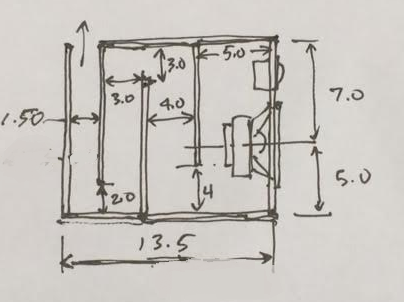
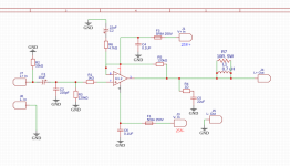
The design of the TL was as follows with a 6.0in wide internal dimension:

510906d1445842501-pmc-tl-stuffing-pmc-tl4-dc130a-8-plan.png


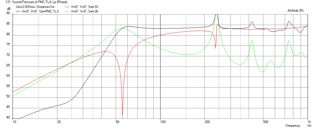
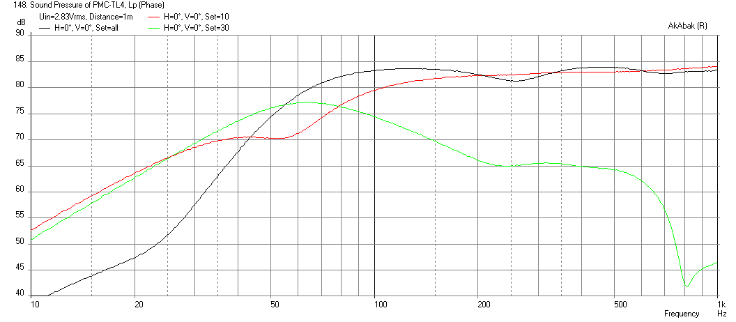
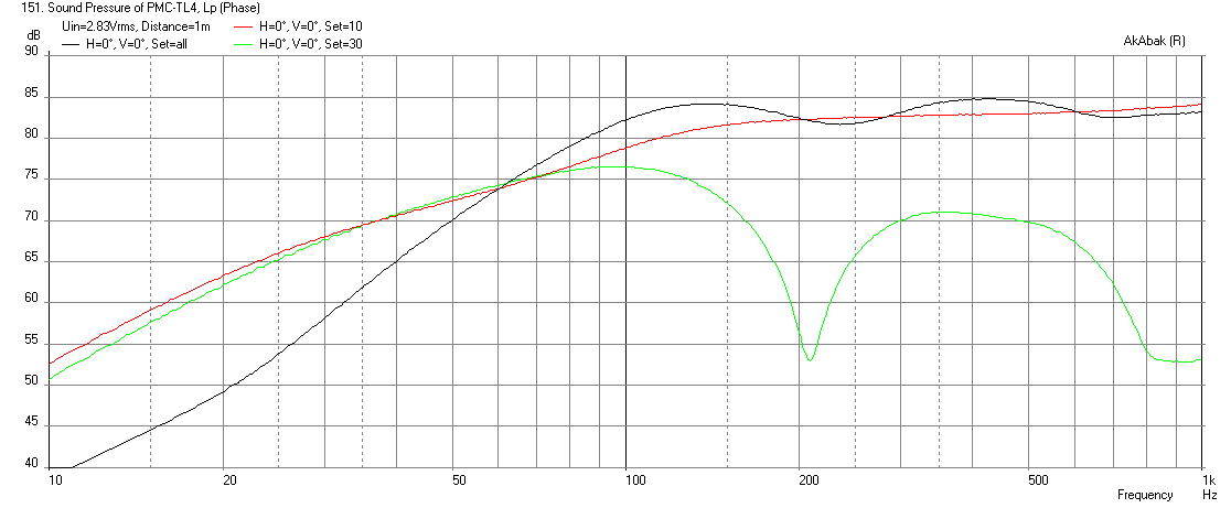
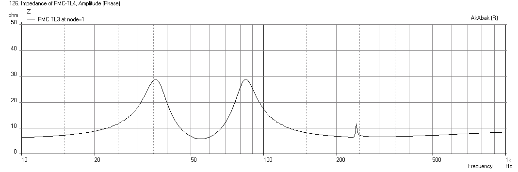
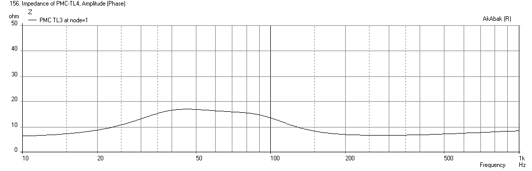
The predicted frequency response for this TL depended heavily on the amount of stuffing inside. Here are 3 cases of light, moderate, and dense stuffing. As expected, each case is a tradeoff in bass extension and SPL for light damping with lower group delay and improved transient response with dense stuffing. The predicted impedance curves go from double peak for light stuffing, to single peak for dense stuffing. The dense case tends to an aperiodic TL.

Light stuffing:

510907d1445842501-pmc-tl-stuffing-pmc-tl4-dc130a-8-freq-no-stuffing.png


Moderate stuffing:

510971d1445868546-pmc-tl-stuffing-pmc-tl4-dc130a-8-all-stuffing-freq.png


Dense stuffing:

510972d1445868546-pmc-tl-stuffing-pmc-tl4-dc130a-8-all-stuffing-tight-terminus-freq.png


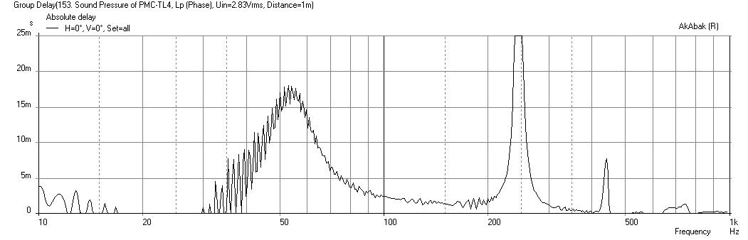
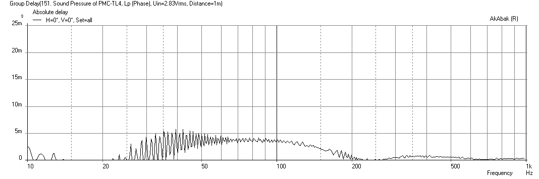
Here are the corresponding Group Delays for the light to dense stuffing, the GD goes from 16ms down to under 5ms at 50Hz which is about the same as a sealed cabinet, but with deeper bass extension.

Light:
510976d1445868546-pmc-tl-stuffing-pmc-tl4-dc130a-8-all-no-stuffing-gd.png


Dense:
510975d1445868546-pmc-tl-stuffing-pmc-tl4-dc130a-8-all-stuffing-tight-terminus-gd.png


Here is the predicted impedance for light stuffing:
510909d1445842501-pmc-tl-stuffing-pmc-tl4-dc130a-8-impedance-no-stuffing.png


Moderate stuffing:
510910d1445842501-pmc-tl-stuffing-pmc-tl4-dc130a-8-impedance-stuffing.png


Dense stuffing:
510973d1445868546-pmc-tl-stuffing-pmc-tl4-dc130a-8-all-tight-stuffing-impedance.png


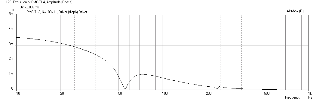
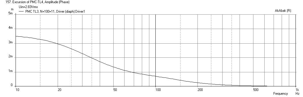
The predicted speaker cone excursion goes from a classic double peak 4th order:
510911d1445842501-pmc-tl-stuffing-pmc-tl4-dc130a-8-excursion-no-stuffing.png


To what you would see in an aperiodic TL or a sealed cabinet:
510974d1445868546-pmc-tl-stuffing-pmc-tl4-dc130a-8-all-tight-stuffing-displ.png


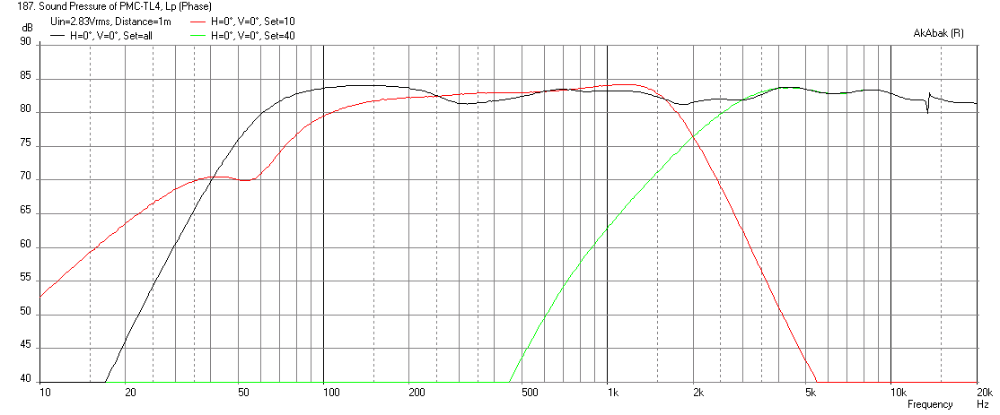
So these plots intrigued me and I decided to go with a prototype build in foam core. I was aiming for the moderate to dense case somewhere in between. I thought it important to get at least a -3dB point at 80Hz to get a sense of some bass output. I redid the model with front exit vent and the stuffing plan closer to how I will implement it using loosely teased out polyfill. Here is the predicted frequency response with a 2kHz XO and baffle step loses included:

511350d1446012673-pmc-tl-stuffing-pmctl4-dc130a-dc28f-freq-moderate-stuffing.png


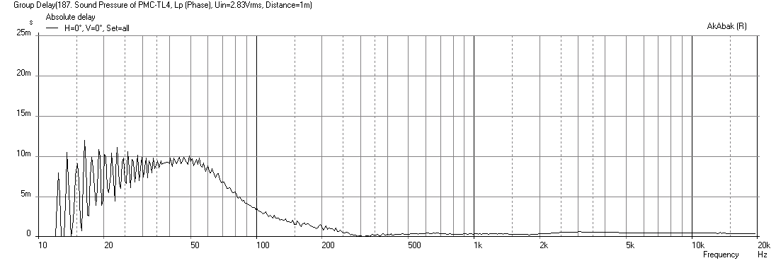
And here is the predicted GD:
511351d1446012673-pmc-tl-stuffing-pmctl4-dc130a-dc28f-gd-moderate-stuffing.png


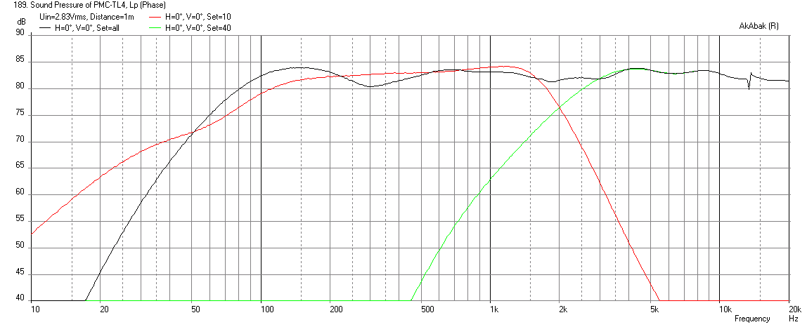
If stuffing is added to the final leg, here is the predicted response - about 80Hz f3:
511352d1446012673-pmc-tl-stuffing-pmctl4-dc130a-dc28f-freq-dense-stuffing.png


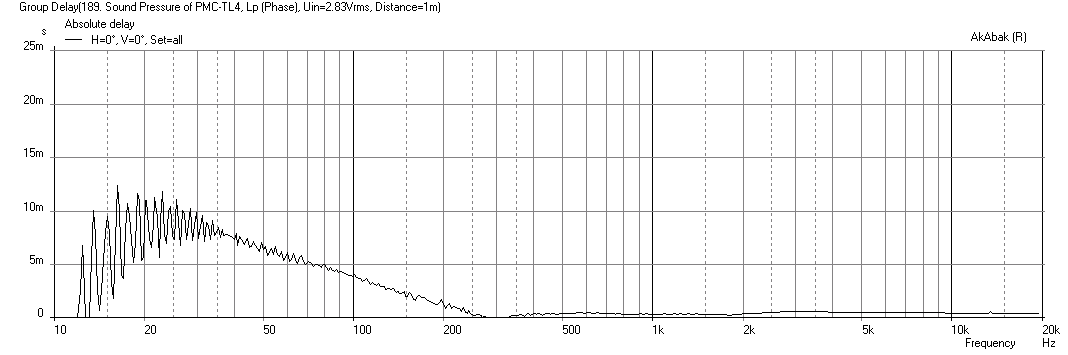
With about 7ms GD at 50Hz:
511353d1446012673-pmc-tl-stuffing-pmctl4-dc130a-dc28f-gd-dense-stuffing.png


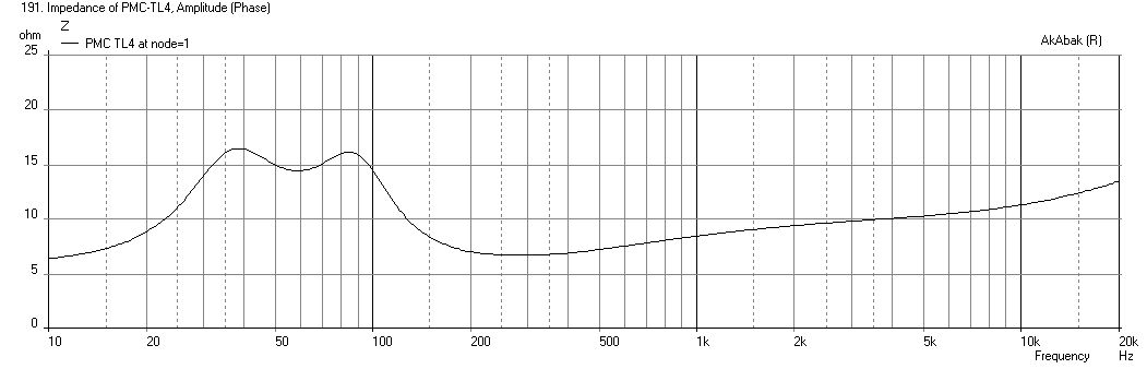
With a semi-bordering on aperiodic TL impedance peak with a mild double bump:
511356d1446013092-pmc-tl-stuffing-pmctl4-dc130a-dc28f-imped-dense-stuffing.png


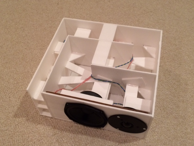
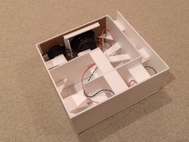
Anyhow that was the goal and here is the build process:

511112d1445927932-pmc-tl-stuffing-pmc-tl-dc130a-photo-1.png


511113d1445927932-pmc-tl-stuffing-pmc-tl-dc130a-photo-2.png


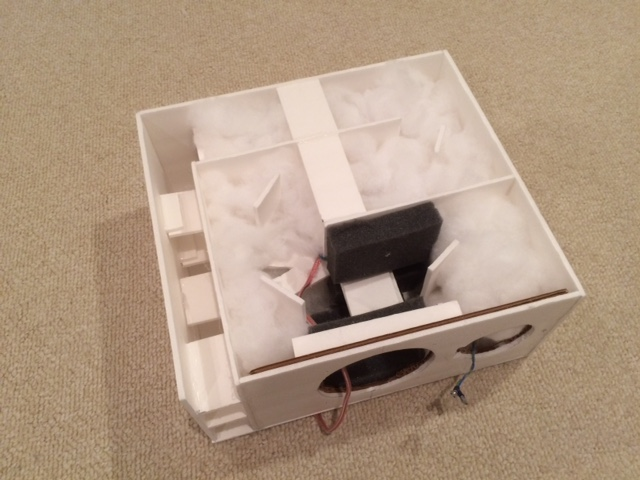
Stuffing plan (adding stuffing in final leg transforms to aperiodic TL):
511619d1446149258-pmc-tl-stuffing-pmc-tl-build-stuffing.png


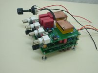
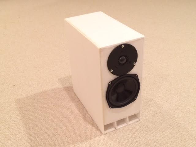
Here is the completed speaker:

511678d1446171313-pmc-tl-stuffing-pmc-tl-build-completed.jpg


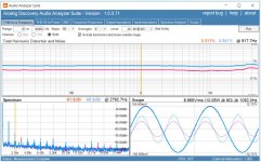
And here are the measurements using a miniDSP and TPA3116D2 amps for an active 2-way. I am using 1st order electrical HPF at 2kHz on the DC28F and a 4th order BW low pass at 1kHz on the DC130A to get an acoustic XO of about 1350Hz. The slopes are quasi-Harsch and allow somewhat of a time-coherent output. I will refine the XO later but these are just to get started.

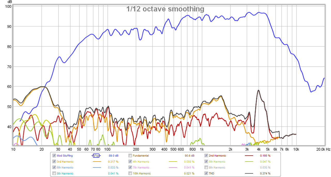
Raw measurement of the woofer in the TL running full range:
511679d1446171313-pmc-tl-stuffing-pmc-tl-meas-freq-raw.png


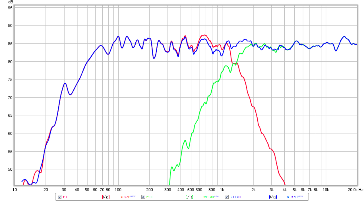
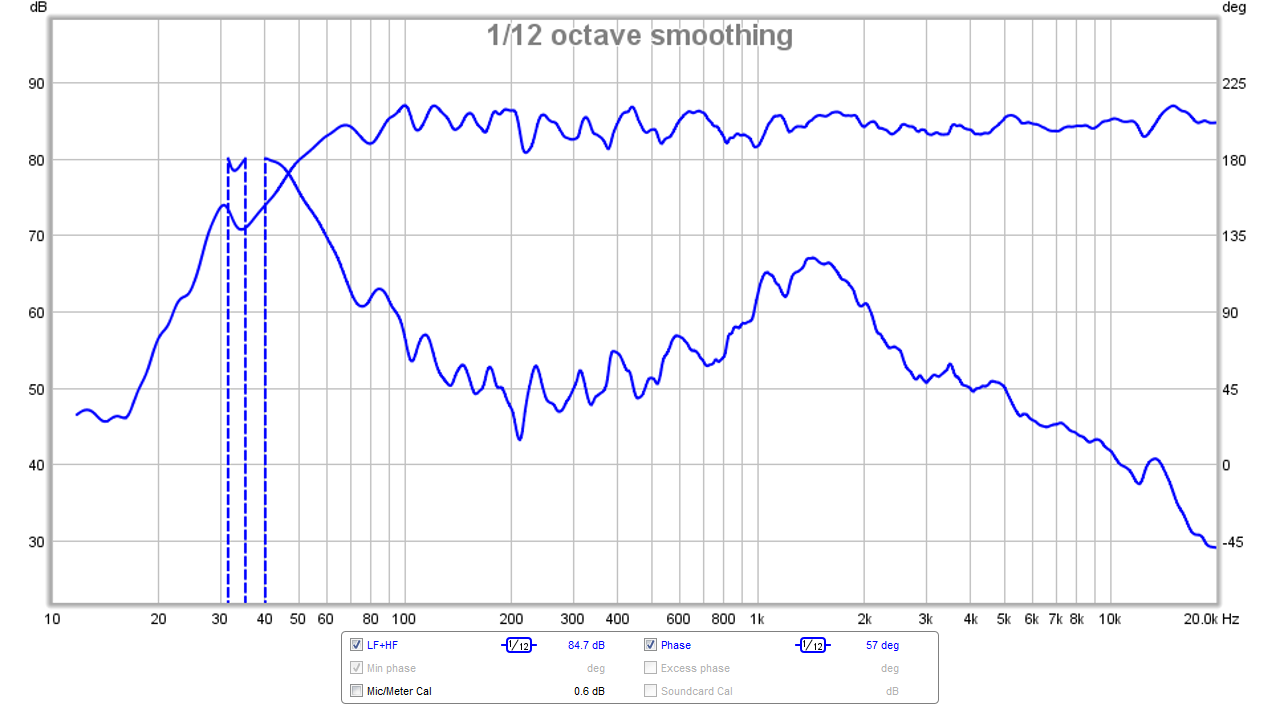
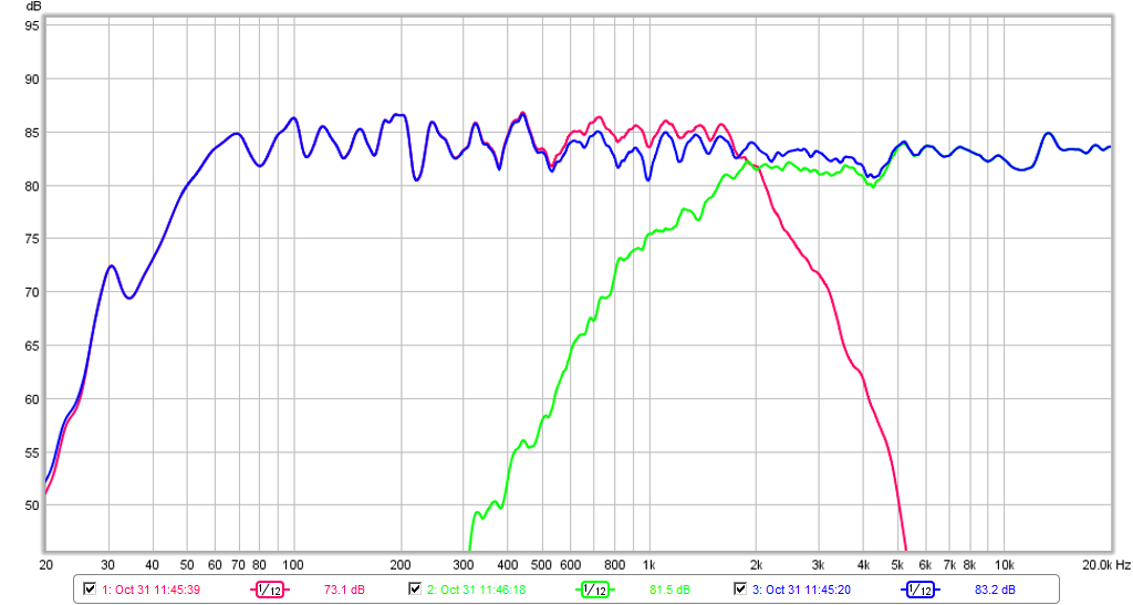
Frequency response showing XO profiles:
511680d1446171313-pmc-tl-stuffing-pmc-tl-meas-freq-xo.png


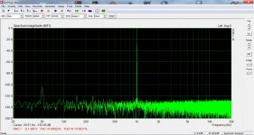
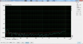
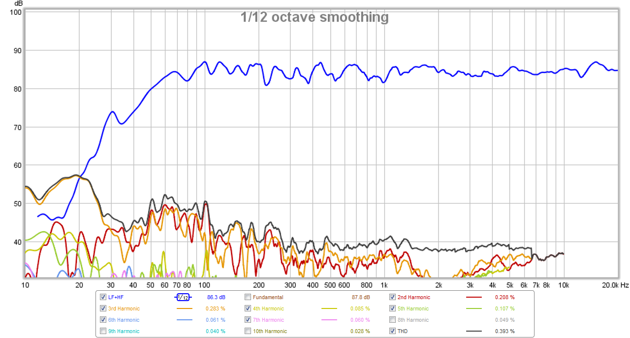
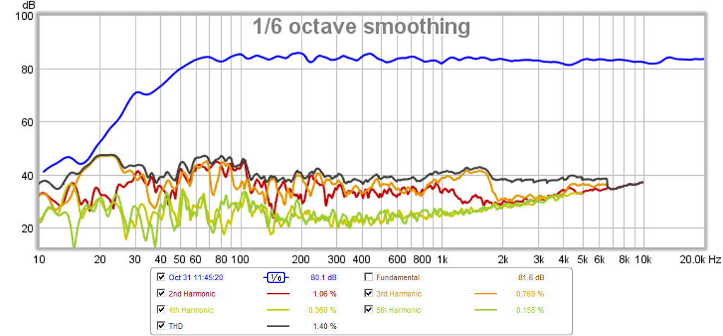
Harmonic Distortion:
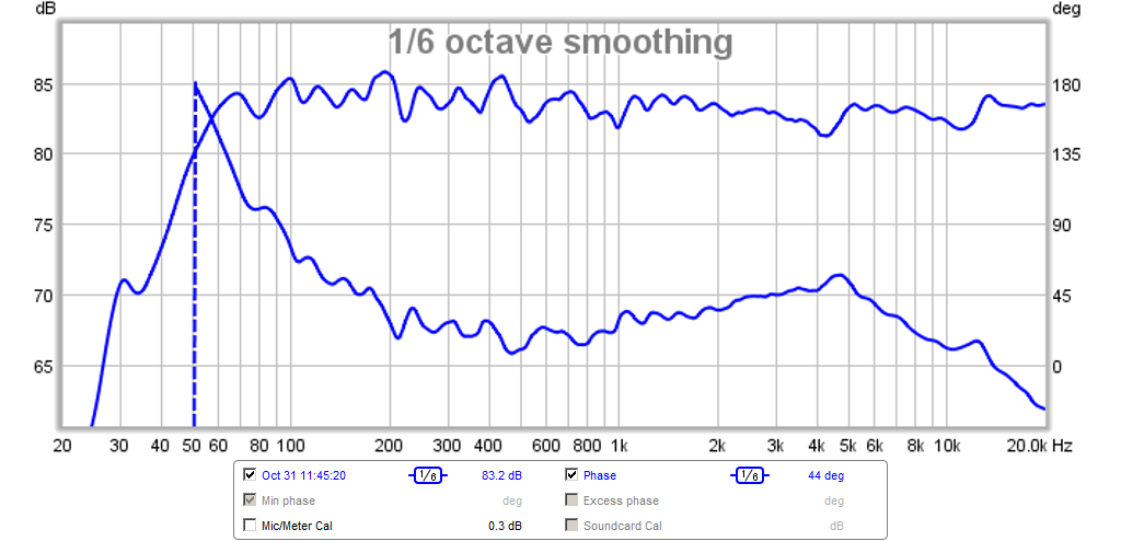
511681d1446171313-pmc-tl-stuffing-pmc-tl-meas-hd.png


Phase:
511682d1446171313-pmc-tl-stuffing-pmc-tl-meas-phase.png


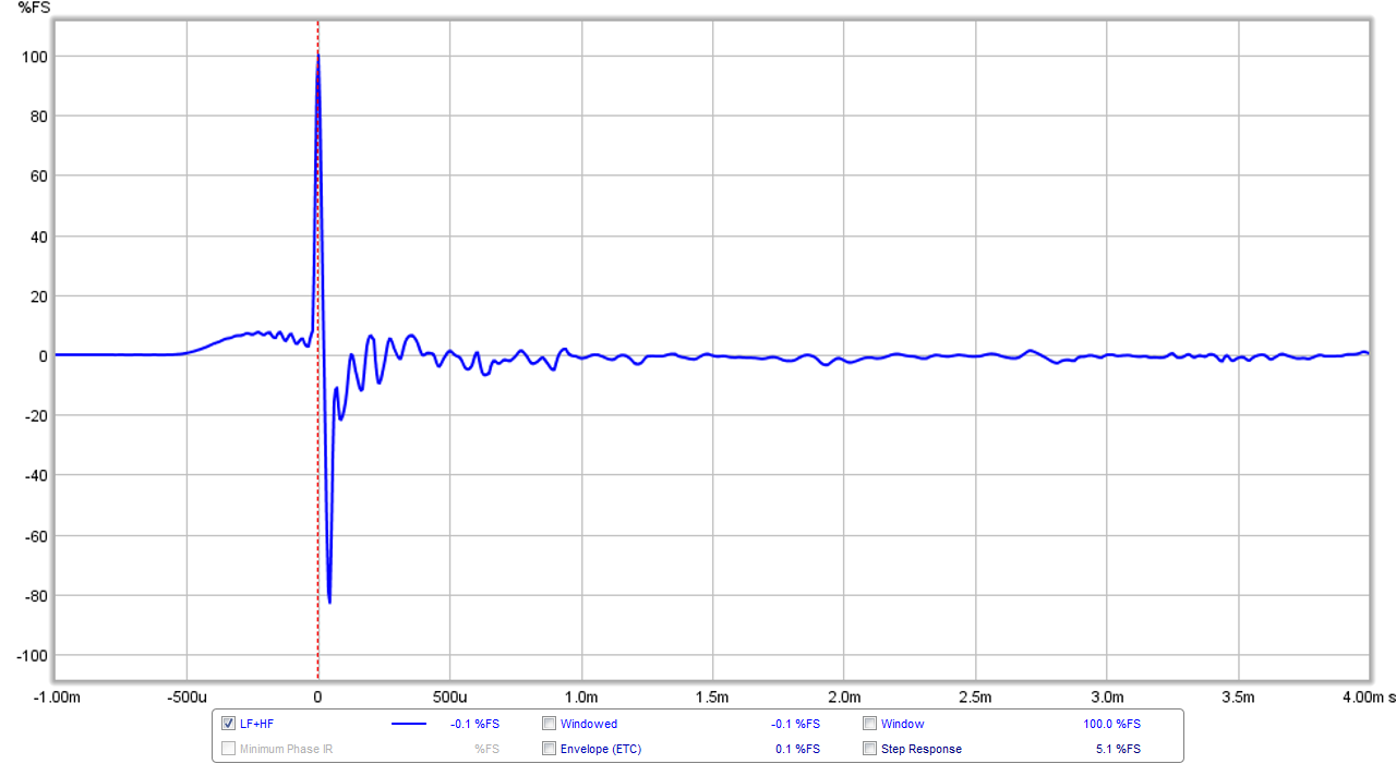
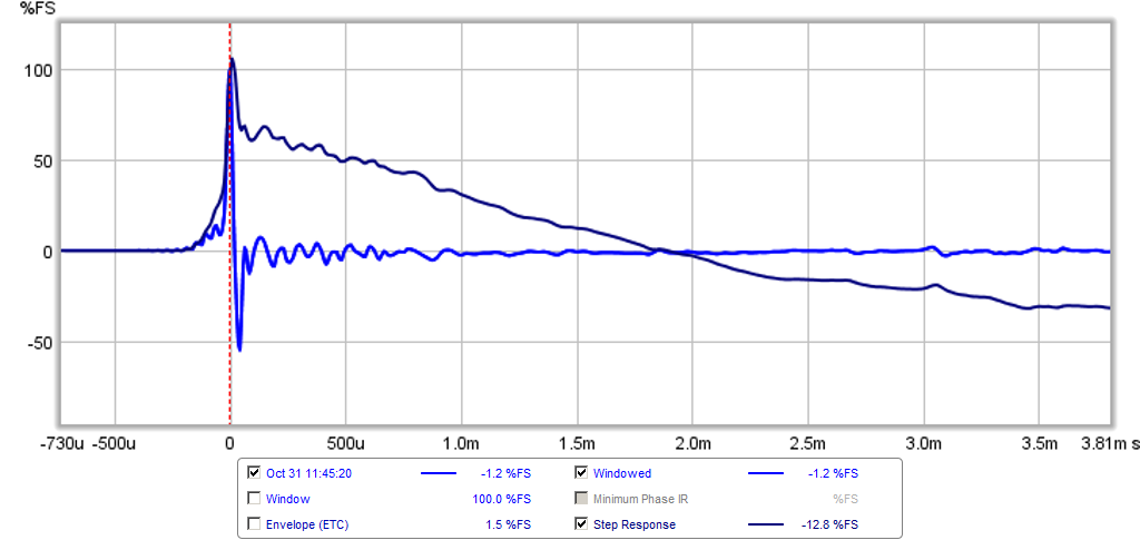
Impulse Response (there is a slight rise and wiggle before the main pulse due to the time delay on the tweeter to get it to be quasi transient perfect with the woofer):
511683d1446171313-pmc-tl-stuffing-pmc-tl-meas-ir.png


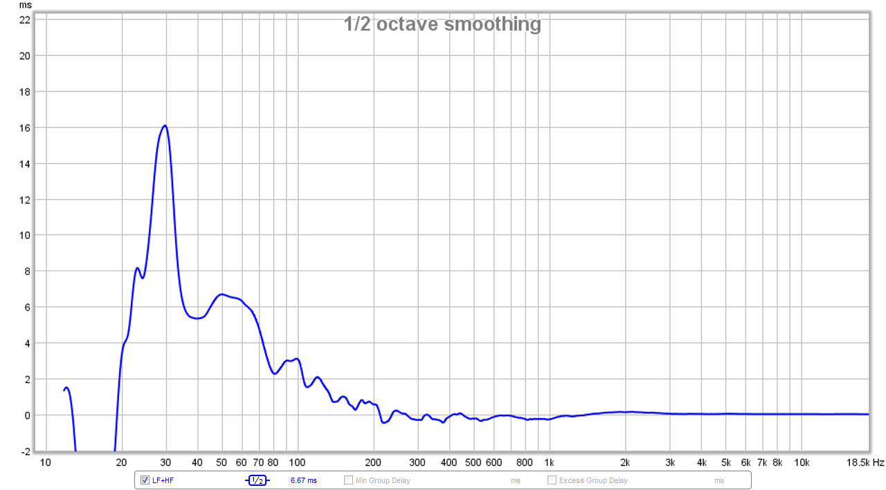
Group Delay (with 1/2oct smoothing for clarity) is about 6.7ms at 50Hz:
511684d1446171313-pmc-tl-stuffing-pmc-tl-meas-gd.png


I did take impedance sweeps and they look a lot like the mild double bump prediction above.

The TL sounds very nice - the transients are well aligned in time between the two drivers, the bass is clear and precise without the muddiness of a reflex, the mids are articulate and pleasing, and the highs of the DC28F are excellent - very smooth, transparent, engaging, with no sibillance or harshness. I still need to do more work to refine the XO with careful measurements and simulation in PCD, then transfer to miniDSP rather than doing the XO "by eye". I think I might move the XO up towards the 2kHz point but see that there is additional HD from the woofer there to avoid. If I have time, I may even try to design my first passive XO to see how that looks. Of course it won't be transient perfect given the flush baffle.

I am quite happy with how these turned out and am considering a thin 3/16in Sureply wood baffle to permit the drivers a better mount.

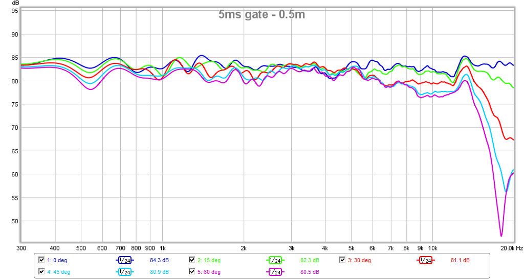
Edit 10/31/15: Polar data shown has tweeter rebated and brillo pad diffraction reducers installed

512027d1446305118-low-cost-pmc-inspired-tl-monitor-dc130a-dc28f-pmctl4-2khz-polar-rebate-brillo.png


Edit 10/31/15 - latest Measurements with 2kHz XO and rebated tweeter with brillo pad diffraction control - sounds great and settings are now"locked down" for enjoyment (and to build stereo pair):

XO plot:

512031d1446307612-low-cost-pmc-inspired-tl-monitor-dc130a-dc28f-pmctl4-2khz-xo-rebate-brillo.png


Phase - +/-23deg over 150Hz to 15kHz :

512032d1446307612-low-cost-pmc-inspired-tl-monitor-dc130a-dc28f-pmctl4-2khz-phase-rebate-brillo.png


Harmonic Distortion - about 1.4% at 50Hz at normal listening levels:

512033d1446307612-low-cost-pmc-inspired-tl-monitor-dc130a-dc28f-pmctl4-2khz-hd-rebate-brillo.png


Impulse Response/Step Response - very nice:

512034d1446307612-low-cost-pmc-inspired-tl-monitor-dc130a-dc28f-pmctl4-2khz-ir-sr-rebate-brillo.png


Group Delay (8.6ms at 50Hz - increased 2ms due to BW1 HPF at 32Hz):

512035d1446307612-low-cost-pmc-inspired-tl-monitor-dc130a-dc28f-pmctl4-2khz-gd-rebate-brillo.png

The Pit Vipers

Hey,
Planning on building the Paul Carmodys The Pit Vipers.
Built a couple of amps and pre-amps with a lot of help from this amazing forum.

Recently got a workshop in my possession so I think its time to make a couple of speakers now when I have the space.
The plan is to make something quite simple and I found the Pit Vipers which seem pretty straight forward.

I do have a few questions though. (probably stupid)
1. What is the best kind of material for this kind of speaker? MDF?
2. The plan that Paul Carmody doesnt specify the thickness of the material. Can I just assume the thicker is better? Thickness would change the volume but not to any large extent.
3. He is using a 6" PVC end cap on the midrange. Wouldn't be better to make a proper enclosure?
4. How much damping should be done? All sides, top/bottom?

Greetings from Istanbul

Hello! My name is Deha.
I live in Istanbul, and I work as a mechanical engineer. I have a strong interest in technology and problem-solving, which aligns perfectly with my profession.
In addition to my work, I have a hobby of repairing electronic devices. This hobby allows me to combine my technical skills with hands-on experience, and I find it both challenging and rewarding. I enjoy exploring new opportunities for learning and development, and I am passionate about developing myself both personally and professionally.

audio analyzer for digilent analog discovery

This looks interesting, especially if like me you're a measurement newb and already have a Digilent Analog Discovery.

Anyone here give it a whirl yet?

Audio Analyzer Suite for Analog Discovery 1 & 2

- THD+N vs Frequency
- THD+N vs Power
- Intermodulation Distortion
- Frequency Response
- Input Impedance
- Output Impedance
- Spectrum Analyzer w/function gen
- Oscilloscope w/function gen

BK

Attachments

  • Capture.JPG
    Capture.JPG
    125.8 KB · Views: 1,549

Question about Dissipante inner baseplate

Does anybody know why the CAD drawing for the Dissipante inner baseplate is showing the mounting holes on a 10 mm x 12 mm grid, rather than the specified 10 mm (square)? Not sure if all the files are that way, but definitely for the current version uploaded for the 3U 300.

Really threw me for a loop when I tried duplicating the hole pattern on that thing.

LM3875 with SMD

I plan to build a gainclone, but i want to use SMD as much as possible. ( just for fun and learning soldering at the same time, nothing else )
I have both caps and resistors as 0805, but i wonder if thats enough ?
Do i need some 3 or 5W resistor as anywhere except the one on the output ?

Ahh, it's a LM3875, but that's already in the header.

Attachments

  • diyaudio-1.png
    diyaudio-1.png
    258.6 KB · Views: 126

Hi from Australia

I've been lurking on this forum for a while but only recently made an account. I've been building speakers for about five years now - intially simple boxes, then a large 3-way open baffle system around some Wild Burro Betsy drivers, then Frugel Horn XLs, a self-designed curved line array, some Cornucopya spiral horns, and most recently some Karlsonators that I will post about in that thread once this intro gets approved.

Enclosure width + depth that becomes effectively in-wall size?

If an enclosure is hung on a wall is there a width and depth size that makes the speaker behave as if it is in-wall?

For example, if you have and enclosure that is 6.75 inches deep (1/4 wavelength for 500Hz) can you make it a 27 inch wide baffle (500Hz wavelength) to make it behave as if it was installed in-wall? In other words, whatever depth your enclosure is you need to make it as wide or wider than the full wavelength that corresponds with the 1/4 wavelength depth of the cabinet if you want it to behave as if it is in-wall. Assuming driver generating that frequency range in the center of that 27 inch wide/tall baffle, although, maybe that isn't necessary.

  • Poll Poll
The Best Format

Which music format is best?

  • Vinyl Record

    Votes: 6 30.0%
  • Tape (Reel to Reel, Cassette, 8 Track, etc.)

    Votes: 2 10.0%
  • Compact Disc (CD)

    Votes: 10 50.0%
  • Electronic (Streaming, YouTube, Mp3, etc.)

    Votes: 6 30.0%

So here's the argument: vinyl is best, because it's really actually a physical transcription of audio. Others say CDs - they're clearer. And then reel to reel, cassette, 8 track, and those, I'm not totally sure what all the advantages are there. And now we have streaming, YouTube, Mp3, etc. I guess because it's easier.
So I'll let you take your pick in this poll. What do you think is best?

Opamp rolling for Aune X1s

The Aune X1s dac uses 2 NE5532 for I/V converter and 1 NE5532 for LPF/buffer and I want to change the NE5532s to newer and better opamps.

2 things I have noted from looking at the circuit board so far:

1. The power supply coupling is close to the opamp but not the best practice. The 2 coupling caps are located near pin 8, so the negative supply pin with not get the best coupling. (Please refer to the image i found on the internet below).

2. There is no ground plane or any traces on the bottom layer below the opamp.

I'm thinking of LME4562 and OPA1612 which are unity gain stable, not to high band width, decent slew rate (>20V/uS).

I have 3 questions/topics to discuss as follows:

1. Will OPA1612 or LM4562 be a big improvement or the NE5532 is good enough?
2. Will the OPA1612 or LM4652 be stable in this circuit?
3. Is there any better opamp that suits this circuit. I'm also thinking of something fast like LT1469 or LT1358.

Thank you!

fncx5eH.jpg

Front panel VFD and control knobs modules

Hi,

I was looking for a display for my DAC project and found 256x48 VFD displays sold in bulk. They looked good so I bought some and made a PCB with everything needed to power and control it.

5363838807931216329.jpg


Module size is 170x46 mm (display itself is 150x40)
192khz.jpg


To control it I put a STM32 MCU and since the MCU is already there, it makes it logical to make it useful for process all other front panel knobs: encoders, buttons, leds, potentiometers etc. Of course for a specific build it is better to just put everything on one board but at the moment exact set of controls needed is unknown so I've tried to make it somewhat universal by putting two FFC connector on both sides for expansion modules:

5366276700087902373.jpg


On each of these expansion boards there are 2xI2C buses, one MCU ADC input and 6 gpios (unique for both sides).
Main 12pin header has supply input (5V), and MCU GPIOs. Pins are chosen so that I2C, SPI and UART peripherals are available here. So again, pretty universal.
Schematic is nothing special, it is attached.

I do not have the side expansion modules yet but for my purposes I'm going to have encoder with some LEDs+buttons.

Regarding the firmware: the display is supported by u8g2 library which makes it really easy to do some sketches with lopaka app:
5364090054928098466.jpg


I'm sharing this because I have more such modules assembled that I really need and consider selling these in future, the firmware for MCU is also going to be published.
But I have two questions:
1. Maybe it makes sense to create some 'default' firmware for those who don't want to deal with MCU coding? For example, firmware which receives I2S WCK and prints current sampling rate etc.
2. What kind of expansion modules are needed? Of course it is not possible to make it 100% universal.

Attachments

  • Like
Reactions: mgb1965

For Sale DCX2496 pro

Hello, This is a behringer ultradrive dcx2496 pro bought around year 2011. It has been in use for approximately 5 years in that timespan.
Perfectly working. Comes with two long cables . Asking $175.
Shipping to canada at buyers expense.
Regards

Attachments

  • DCX-1.jpeg
    DCX-1.jpeg
    461.3 KB · Views: 86
  • DCX-2.jpeg
    DCX-2.jpeg
    243.1 KB · Views: 103
  • DCX-3.jpeg
    DCX-3.jpeg
    348.3 KB · Views: 92

Rogers LS4a Tweeter Replacement

Hi all -

I have a pair of Rogers LS4a's that I dug out of storage and have finally decided to resurrect. One tweeter is blown.

The original tweeter is a 19 mm aluminum type manufactured by Seas - Model H414 TAF/G. They are no longer available. In my research, about a decade ago, it seems like the accurate replacement became the Model H0532.

However, now it seems that this model is no longer readily available.

Before I reach out to Seas directly, I figured thatI would post on the forum to see if anyone knows of an alternative tweeter that would work well or a source for either of the Seas recommended ones.

Thanks!

Jon

Extract audio from HDMI

My recent upgrade from a Raspberry Pi 4 to a Pi 5 left me without a convenient audio out. So I thought I would get a HDMI audio extractor. We'll I did, and I am disappointed. I thought with this device I could replace my Windows 10 Dell all-in-one that I use only for streaming Pandora. I feed the PCs headphone out to my little 6BM8 tube amp and small near field speakers. I really dig the sound from this,but when I switched to the HDMI extractor the sound quality diminished.

The device I bought is supposed to handle 4k at 60Hz, so I thought it would do a good job. Anyone have experience with extracting audio from the HDMI output? I know it's not ideal, but really, should there be that much difference between these two ways of playing audio from say Pandora?

Thanks in advance,
Roger
Projects by fanatics, for fanatics
Get answers and advice for everyone wanting to learn the art of audio.
Join the Community
507,624
Members
7,880,654
Messages

Filter

Forum Statistics

Threads
405,890
Messages
7,880,654
Members
507,624
Latest member
Neilonpoint