Some vintage Philips drivers and Motorola

Hi

I have here some vintage drivers I used mainly in my full range experiments.

1 pair of AD8082M4 8" full rangers (these were my favourites); I used them in a TQWT. There is some scarce info on them on the web. These are in a good condition given their age. No damage to membrane, wizzer, surrond look also good. The only thing which has somewhat deteriorated is the foam seal on the frame edge. £15 + shipping

1 pair of 5" full rangers; I think it is AD5018. These used to be in pristive condition, but I managed to damage one wizzer and one surrond (see photos). £8 + shipping

1 pair Motorola piezo's. Can add the small baffles seen in the pictures. £7 + shipping

1 pair Philips tweeters. Here I removed the strange protective grill which probably has not been there to improve the sound quality. I have similar baffles as Motorola's if anybody wants them. £4 + shipping.

Attachments

  • DSC_7020a.jpg
    DSC_7020a.jpg
    438.5 KB · Views: 467
  • DSC_7021a.jpg
    DSC_7021a.jpg
    372.7 KB · Views: 471
  • DSC_7023a.JPG
    DSC_7023a.JPG
    160.8 KB · Views: 462
  • DSC_7024a.JPG
    DSC_7024a.JPG
    158.1 KB · Views: 448
  • DSC_7029a.JPG
    DSC_7029a.JPG
    144.7 KB · Views: 438
  • DSC_7030a.JPG
    DSC_7030a.JPG
    186.9 KB · Views: 110
  • DSC_7031a.JPG
    DSC_7031a.JPG
    156.7 KB · Views: 107
  • DSC_7032a.JPG
    DSC_7032a.JPG
    155.7 KB · Views: 119
  • DSC_7033a.JPG
    DSC_7033a.JPG
    181 KB · Views: 102

LME49710NA Pre Amp vs. OPA 627

Hello all. Been quite a few years since I have listened to anything due to health issues and other rough patches. This past year I decided to try to get back into listening. So I have built a few Dyna ST 70's using VanAlstine boards and enjoy the sound. Was pondering on getting a Preamp off ebay, since funds are very tight. I did find a unit that appears to be dual mono design with tone controls. Appears to be straightforward and comes with op amps. The seller claims that the op amps can be switched. I can order the unit with LME49710NA op amps or OPA 627's. I have no knowledge on the difference and hope someone can honestly point me in the right direction. Basically need to know if I can switch out op amps like I do tubes in the Dynaco St 70. Thank you in advance for your help.

Studio amplifer

I never noticied any reference about the STUDIO amplifier
designed by Dr. Borivoje Jagodic, or simply Bora. Perhaps
I never tryied hard to look for these postings if there are any.
But the purpose of my conversation today is to underline
the quality of this design, as per this:

I made his Studio amplifier and Omni protection board, Studio is excellent amplifier, very nice sound and superb stability, it is my first diy amplifier, and I am very pleased, Thanks Bora!!!,

Vinko

Attachment: studiosema.pdf

Of course this contradicts what I said at the beginning but
it was taken from another posting out of the context.

What I'm triyng to say is the STUDIO is one of the few amplifiers
I have built that gives me the pleasure and satisfaction of an hi end device. It's very articulate and capable of revealing all
the goods and bads of a CD.
Bass response is excellent, mid range and treble smooth and
crisp but above all the sound stage is the most avident
caracteristic of the qualities of this amplifier.

I built one a few monts ago for a project being still under development, but I think I'm going to keep as it is, i.e. an
amplifier made to judge others, and I have a few, actually
too many...

question about Sanders' PCB ESL stators

The patent application of Bloodworth and Sanders, found here, describes a method for fabricating electrostatic loudspeaker stators out of copper clad boards (printed circuit board material). One of the features they cite is the "complete encapsulation" of the conductors by the dielectric material. To do this, they use CNC machining to cut slots through the boards, and also cut back the copper trace so that there is a copper-free region between the edge of each trace and the slots that surround it (see figure, extracted from patent application). They then cover the copper traces with another slotted board to complete the encapsulation.

My question is: How important is the gap between the copper trace and the slots? I assume the gap is intended to provide insulation in the plane of the stator, but is that necessary? If not, it seems that a slotted printed circuit board stator could be made without resorting to CNC machining. I'd love to build a CNC router, but spending $2k to build the router is a bit hard to swallow. I can imagine much cheaper, albeit more labor intensive, methods for achieving the same ends as long as the gap between the copper and the slot can be eliminated without running into problems. For example, I have a cheap, plastic tile cutter with a diamond blade that does a great job of cutting PCB material. I can imagine using its blade to cut parallel slots through the boards without resorting to the complexity of a full CNC router.

Thoughts on the importance of the gap between the copper and the slots? The patent application states clearly that one of the main advances they lay claim to is the solution to the problem of insulating the edges of the copper traces, but is that really a big problem?
Few

Attachments

  • Untitled-1.jpg
    Untitled-1.jpg
    93.1 KB · Views: 758

Lanzar OptiDrive 100.4 (Zed amp)

This amp has some similar problems to the old notes I have on some of these Zed amps. I would say this amp is sort of similar in design feel to a Hifonics Generation X, but definitely not 100% the same.

No fets seem noticeable shorted. I checked all FETs and most of the drivers and all are checking -ok- while on the board. Still clamped to the heatsync for now.

This amp attempts to power on but falls directly into Protect. I tried my 5A supply and also through a 20A fused link and it still goes into protect after about 5 seconds.

PS is set to 13.65vDC, 5A max CC. OCP at 5A trips out so it may be trying to pull above 5A if it wasn't prevented from going into protect.

I've taken note of readings on the TL494 and the LM324 as follows. I think these may be OK but something is causing protect to engage.

TL494
1: 2.321
2: 2.935
3: 4.80
4: 0.224 (Initially 0.92)
5: 1.473
6: 3.462
7: 0.000
8: 13.65
9: 0.000 (Initially 2.12)
10: 0.000 (Initially 2.12)
11: 13.65
12: 13.65
13: 4.98 (Initially 5.00)
14: 4.98 (Initially 5.00)
15: 4.98 (Initially 5.00)
16: 10.96 (Initially 11.24)


LM324
1: 0.003 (Initially 12.00)
2: 12.56 (Counts from about 3v up to peak)
3: 6.75 (Initially 7.64)
4: 13.56
5: 8.99 (Initially 9.60)
6: 12.58 (Counts from about 2v up to peak)
7: 0.004 (Initially 12.20)
8: 0.003
9: 0.003
10: 0.000
11: 0.000
12: 12.14 (Initially 3.71)
13: 8.95 (Initially 9.50, then drops to 0.000, then up 8.95 across about 2 seconds each)
14: 11.72 (Initially 0.68)

Rail voltage actually pulses up to +-19.35vDC before going into protect.

I checked for any pulses of DC across speaker terminals. Channel 1 seems to have an issue, referencing non-bridged speaker terminals. The following figures are PULSED to speaker terminals before dropping back to 0vDC

CH1: -17.44vDC
CH2: +-0.5vDC
CH3: +-0.3vDC
CH4: +-0.4vDC

From here, I'm thinking I may want to try and have the amp come up without protection, so that I can measure things on Channel 1 and see what might be wrong or different.

Can I carefully lift a few pins of LM324/TL494 to force boot, or should I check something else first?

Thank you

Nelson Pass's LX Mini Analog Crossover

I recently upgraded from the 2 way ASP to the 3 way ASP.

The 2 way ASP that I assembled is now sitting on the shelf.

I will be keeping the power supply so you will need to provide your own PS.

The following Google Photo Link shows pictures of the 2 way ASP I am selling:

Nelson Pass's LXmini Analog Crossover - DIYAudio - Google Photos


$225 + $15 USPS 2 day shipping. Sold only within the U.S. 48 contiguous states.

I have this listed on other sites as well.

Thanks.

Help Needed with F5 Turbo V3 Monoblock Bias Issue on Startup

I'm desperate for some help guys.

I've finished my F5 Turbo monoblocks. They pass the dim bulb test. They bias beautifully with almost no DC offset.

Twice, however, I've blown the outputs on startup and had to replaced all the mosfets (which is getting expensive).

The issue seems to be that wherever I set the bias, that I when I turn the amp on cold, the bias jumps much higher on startup.

Twice I biased it perfectly and then after the amp was cold and I turned it on---- POOF.

The third time I set the bias very low, around 125mv, let it sit for a while, and then on startup the bias starts around 350mv and slowly drops down to the set range.

I'm pretty sure that when I biased it around 300mv, the bias jumped to over 600mv when started up cold.

The issue is not the outputs (just installed) or the 1ohm resistors (just replaced them. Could it be an issue with the diodes? I have not replaced those, but I'm doubtful that they could have blown.

Any other ideas on what to check or replace? Like I said, the thing is so stable and biases perfectly. The only issue is on startup.

Would be so grateful for any help.

Delta 15 LFA in a QWTL

Hey Team. Long time no post.

I have recently moved house to a smaller listening room and a I really dont have the space to setup my Stereo Eminence Delta 15 LFA OBH-Baffles....

So I'm thinking of putting the 15's in QWTL cabs just for a bit of fun and the "I haven't heard large PA drivers in TL's before" factor which may or may not be worthwhile.... So before I make the sawdust I thought I would develop a design here and see if its viable.

This is also an opportunity to learn Hornresp which I have been really keen to do for a few years so I would like to keep the focus on that software.

Screenshots to follow....

NAD 2200 wrong rail voltages

I have been working on a NAD 2200, which had a number of fried components centered on Q308. I replaced the damaged components and then when the protection clicked off thought, excellent all solved.


I then did my usual recap (which I done many times) and had the amp ready to bias . Then I discovered the problem.


The right channel has 90v (both +ve and -ve) on the collector of each of the output devices, whereas it should be 60v. There is a detector stage Q322/Q324 which switches the rail between 60v and 90v to achieve the class G operation and the additional headroom that provides. ("Power envelope").


I have replaced D330 and D332 and Q328 and Q326 (KSC2690 and KSA1220 respectively). I have even replaced Q330 and Q332 as these had been earlier replaced as well.


The voltages on the detectors Q324/Q322 measure as they should, but I am at a loss as to why 90v is going to the collectors of all the output s (Q316/Q320/Q314/Q318).


I have replaced Q306/Q308 and Q302/Q304 although all these tested fine as did Q334 and Q336 which I also replaced.


I then went for my "go to" problem areas with these amps and replaced D312/D310 and ZD302/ZD304 and D322/D318 and D320/D324 as these can all cause issues.


So I am now flummoxed, as the only way I can see the 90v rail getting to the collectors is through the switching circuitry Q326/Q330 for the +ve rail and Q328/Q332 for the -ve rail. The collectors of each of those should be at 60v (+ve and -ve) not the 90v I have now.


I did resolder any connection on the PCB that looked suspect and checked there is an earth to the power supply as well.


Any guidance, thoughts, insights or wisdom would greatly appreciated, as I keep bashing my head into this wall.


Thanks for reading, and circuit attached


Peter

Kicker KX700.5 No sub after low battery.

Just like the title says the amp lost its sub channel after battery got really low, too low to crank the car. The 1 channel works ok, and I don't use the 2 channel, but I get no sound from the sub channel. Swapped RCAs to confirm that the output is present from the head unit.

The amp is not going into protection. Red goes to green as powered on and green light stays lit. I've got +-52V on the class D rail. I've repaired a couple A/B amps but class D isn't my strong suit. Any ideas on where to start, common component failures displaying these symptoms, and any other ideas? Any help appreciated.

How much electricity is used when not playing anything?

I'm sorry if this isn't the best subforum, but I honestly didn't know where was better.

In general, we leave our speaker setups on but turn the sources off (computer, tvs, etc) at the end of the day. For example, my main living room setup is an nvidia shield feeding a minidsp going to two tpa3118 lepais (until I can afford much better amps) to my WAWs.

My wife asked me how much electricity gets used when the amps are on but nothing coming from source and I was ashamed to have no idea. Could perhaps those with more relevant degrees help a biologist out? Thanks ahead!

Equipment damage horror stories, blew it up, or knocked it over.

This guy that worked in the surplus store always piped up at the mention of any audio gear. "I used to have one but my girlfriend knocked it over." No one wanted to inquire as to whether she was an audio Tasmanian Devil or if it was a single, catastrophic event. The less he talked, the better.

In the early 70s, I got a deal on a Teac 3340S, 10.5 reels, 15 ips, 4 discrete channels. I think I might have had 100 hours on it when, during an effort to move things around on my shelf the wires strained and the deck pitched off and onto the piano bench 4 feet below. The Sync buttons smashed the circuit board near the heads, and the right take up motor shaft broke.

My next disaster: I had a BIC with a V15 Type 3. I regularly changed out the stylus, but back then, it cost 45 bucks. For 10 dollars more, I could get a new cartridge and stylus. After installing the new cartridge, I put on a brand new record, closed the dust cover, and proceeded to knock over a 16 mm projecter I was working on. It smashed through the dust cover, destroyed the record and cartridge. The projector was undamaged.


Surely you have some blow up or damage stories.

Force cancellation woofers

Has anyone implemented opposed force cancellation woofer mounting? It is something I want to try. I feel I have explored the limits of box bracing and damping and want to give the force cancelling technique a go. I have a real time spectrum analyser and plan to purchase a 3-axis accelerometer. The principle is attractive but I suspect successful implementation is not that easy. First thoughts are linking the magnets with threaded rod with an adjuster and optimising the tension for minimum box excitation. Some have suggested a resilient pad between magnets but this would surely conflict with the principle. Any hands on experience would be appreciated.

Subwoofer Amp Help Needed! Original ProMedia 2.1

Hello gang!

I am still very much a novice! And that's why I'm here needing help. Unfortunately. But this is a good place still!

I have an old Klipsch ProMedia 2.1 PC speaker setup with 2 2way satellites and a subwoofer. Love it and IMO, worth reviving!

A couple years ago the foam surround on the 6.5" sub woofer speaker crumbled and everything else was still fine. Used it anyway.

A few months ago, I decided it was time to enjoy all of its capable frequency range again and bought a refoam kit and got it done.

Seemed like nothing was happening. Recently, I went in and tested the Sub Speaker amp terminals for DC voltage and thankfully, it was zero. Then with a signal (song) i Measured the AC voltages varying the Volume and Bass pots. voltage ranged with both pots low at 0.011 to both pots very high to 3.+ volts. and the voltage increased as I swept range through both pots.

After attaching the speaker again, it has non distorted output, just very low, and just a little louder with both pots turned way up.

I also have since gotten a new OEM speaker and there is no audible SPL difference.

I have a DMM (no scope) and I am hoping you guys can recommend how to find what or which stage or whatever is allowing signal to pass, just not amplified. And hopefully, a little explaining on how, as signal tracking isn't anything I've done before.

Schematics are linked below. Any help would be greatly appreciated! Thank you all!

Klipsch Promedia V2.1 Amplifier Repair

Wharfedale W2 Speakers (5" drivers)

I'm currently looking to repair a pair of 5" drivers from a set of Wharfedale W2 Speakers. The voice coils are both open circuit.

The literature says that they are Super 5 drivrs but the ones I have do not look like the ones listed in the Wharfedale leaflet. I have atteched a picture and I was wondering if anyone has any experience of these unit.

Any information would be appreciated.

Attachments

  • Super_5.jpg
    Super_5.jpg
    17.3 KB · Views: 182

AR XA build set

Ready to DIY an AR XA? I have a build set including the inner and outer platter, sub-chassis/T-bar, springs w/ top and bottom rubber washers and pulley. You add Hurst motor, wood base /top and your choice of arm.

Not having to pay for a complete table will save you $$$ and shipping cost.

Asking $100.00 + shipping.

Attachments

  • Pulley3.jpg
    Pulley3.jpg
    33.4 KB · Views: 156
  • Pulley4.jpg
    Pulley4.jpg
    95 KB · Views: 158
  • AR_TBar.jpg
    AR_TBar.jpg
    192.2 KB · Views: 155
  • AR_TBar2.jpg
    AR_TBar2.jpg
    165.2 KB · Views: 154
  • ARSprings.jpg
    ARSprings.jpg
    76.8 KB · Views: 152
  • Platter.jpg
    Platter.jpg
    37.3 KB · Views: 67

NSM CD 3101 AC (CDM4 transport) does not play CD-Rs

I recently bought a NSM CD 3101 AC disc changer which cannot play CD-Rs, only the original pressed Audio CDs. I have a second unit of the same model and so far it could play any type of CD. So something must be wrong with my new CD changer.

The CD changer has a Philips CDM4/53 transport and TDA8900, SAA7310 and SAA7321 ICs on the servo PCB. I found a service manual (incomplete) for the player and could upload the servo PCB schematic if needed.

What I did so far to solve the problem:
  • Cleaning the lens of CDM4 with IPA
  • Replacing all the electrolytics on the servo PCB
  • Checked the 3600 pF Polystyrene capacitor as suggested in another thread
  • Checked the BC338 output transistor for the laser power supply

Those above mentioned steps were not successful. Somehow I think that the problem is related to the servo PCB but I really don't know what I should do next. Any help is highly appreciated.

Dont know what I am doing.

I sold a transistor matcher and curve tracer on ebay.

Seller got back to me saying he just doesnt understand it and so has bought an Atlas tester instead.
Fair enough.

The Atlas tester is battery powered so only puts a couple of milliamps through the transistor so is a poor test.
Mine puts through 40mA so is a bit nearer real life.

The Atlas tester displays hfe for one point on the curve.

Mine plots full hfe curve from 0 to 9 volts.

Atlas tester has a tiny screen.

Mine uses pc screen and can be zoomed in on curves and you can pan around.

Mine isnt hard to use, you just connect a transistor and press "read channel 1" on the pc screen. You then connect second transistor and press "read channel 2" and it displays the full curve on the pc screen.
You can do this with up to 5 transistors.
You can then compare curves for matching.
If they are close its a good match otherwise no good.

Vented....

SPP Build

I coloured outside the lines a bit.

The PC board is suspended about 3/4" below the top plate. Tube sockets and some resistors are on the top of the board, all caps and majority of the res are on the bottom. "Iron" was salvaged from an old Heathkit EL84 amp. The power trannie put out a bit too much HV so the rectifier tube was mounted off-board and a pre-filter and choke were added to drop the B+ a bit. Like most old power trannies they run kind of high on the 120+ volts on the AC lines now so I put in the equivalent of 5 ohms in series with the primary. The value needed determined by keeping the filaments at or below 6.3 volts.

OP tube bias is adjustable. I copied the idea from the Parks Dynaclone. A 470 ohm res is bypassed with a trim pot. A 10 ohm res in series with both of these is used to set 35mA draw per tube. Adjustment is accessed from under a cover on the top panel.

Initially a resistor was used between the pre-filter and the main board but a Hammond 1.5H 200mA choke killed the last of the PS buzz.

I didn't install C101, the cap in the NFB loop. The question for all of youse wise guys is what measurement(s) will help me determine the value for C101?

It fired up fine right away except for an intermittent resistor in the 120 volt feed. It was replaced with the trio seen in one of the pictures.

Sound? Better than the Parks Dynaclone with vintage Dynaco OPTs.

Broskie style grommets will be installed around the 9 pin tubes to clean up the looks a bit.

Cheers, Steve

Attachments

  • P1040445ab.jpg
    P1040445ab.jpg
    994.7 KB · Views: 540
  • P1040446a.jpg
    P1040446a.jpg
    843 KB · Views: 514
  • P1040450a.jpg
    P1040450a.jpg
    923.4 KB · Views: 503
  • Feedback cap a.png
    Feedback cap a.png
    9.6 KB · Views: 514

In need of warmth

Hi,

I have my active speaker system. Which sounds exceptionally good. Though, with good recorded, non offensive music. The system is also extremely unforgiving. Any rock more aggressive than Alice In Chains - Unplugged with distorted guitars and other screaming and harsch chracteristics is unlistenable.

I know that no matter how warm you make it, a resolving, low distortion system will always make poorly recorded music sound bad. But I at least want to be able to listen to it without my ears bleeding.

The system is already guite on the warm side in terms of bass response, I like that. But I just can't get rid of that punishing harshness in the mid/high frequencies. I've tried rolling of the treble with a few dB, and a 2 dB dip between 1 and 2 kHz (BBC dip) but it doesn't cut it. In fact, There's not that big of an audible difference.

Does anyone know how to effectively make the system more forgiving?

Some help please - Tube amp Poor frequency response

I'm building a KT88/ EL34 CLASS A push-pull tube amplifier with a board I bought online. I attached the schematics below.
Power enough but the frequency response is poor and drops significantly as from 10 KHz.
The output transformers are supposed to be 5K 60W Push-Pull Ultra Linear, Theoretical Frequency response: 20Hz-25 Khz + -1DB, for KT88 KT100 EL34 6L6 5881.
With KT-88 or EL34 tubes it stays the same (with adjusted BIAS).
I disconnected the negative feedback loop to check if that was causing it but sadly no improvement. For the rest it is a very simple design, so I fear it is caused by the expensive output transformers. Hope you guys (and girls) can suggest or hints to investigate further …
Some specs:
6U8 pentode used as voltage amplifier and triode as differential splitter
360 AC input for B+
B+ 410 Volt (Unloaded 512 Volt)
54UGB Full-Wave Vacuum Rectifier
Separate DC driven 6U8 filaments at 6.26 V DC
KT-88 Tubes biased at 70 mA
From the start replaced all caps with brand new ones.
All resistors measured and good 1 %
Very stable B+
Same result with EL34 tubes.
Any suggestions welcome !

An externally hosted image should be here but it was not working when we last tested it.


An externally hosted image should be here but it was not working when we last tested it.


Measurements.png - Google Drive

Cybernet SRC-80 SRC80 for repair - High Resolution Schematic wanted

under
Cybernet SRC-80 Service
unfortunately there are all pages include the schematic filed in jpg and not the usually used pdf.
In the attachment I try to get the schematic more dark for better reading.
But maybe one of the members have it in PDF and higher resolution.

Cybernet (Kraus) SRC-80 & SCD-80

Attachments

  • QPfy1l3h.jpg
    QPfy1l3h.jpg
    118.6 KB · Views: 304
  • Mw7pkwYh.jpg
    Mw7pkwYh.jpg
    198.3 KB · Views: 271
  • r766HtKh.jpg
    r766HtKh.jpg
    125.1 KB · Views: 235
  • SLgKYOdh.jpg
    SLgKYOdh.jpg
    167.8 KB · Views: 226
  • wS0GOPOh.jpg
    wS0GOPOh.jpg
    115.2 KB · Views: 206
  • DSCF9417.jpg
    DSCF9417.jpg
    761.6 KB · Views: 197
  • wfUa4qah.jpg
    wfUa4qah.jpg
    93.5 KB · Views: 197
  • DSCF9424.jpg
    DSCF9424.jpg
    590.5 KB · Views: 159
  • DSCF9425.jpg
    DSCF9425.jpg
    560.8 KB · Views: 157
  • Cybernet SRC-80 Service Manual-29-dunkel.jpg
    Cybernet SRC-80 Service Manual-29-dunkel.jpg
    1.1 MB · Views: 284

Here we go again... Akai M8 Reel to Reel Conversion

Okay, the last conversion to guitar amp project was a success so it's time for another one! 😀 I have on the way to me 1 Akai M8 Reel to Reel Amplifier, right side only (originally designed as mono with right only engaged or stereo when selected engaging a left side amp). I'm told it's working condition but we shall see how its doing once it arrives. In the mean time lets get planning for what needs to be done.

What we have for tubes:
1 x EF86 & 1 x 12AX7 in preamp,
1 x 6X4 rectifier,
1 x EL84 output

Transformer is putting out 250V

Speaker Out is 8 Ohms

Max output to speakers is 6 watts (probably less)

Schematic is attached with signal path traced out as best I can figure. There is a bit of a convoluted thing where the EF86 is driving the Volume pot and the 12AX7 drives the Tone pot/Speed selector knob. Or at least that's what I think is going on. I'll know for sure when the model arrives.

I'm thinking of gutting this one much further than the last amp and doing something like the 60's Vox AC4 design. Looks to me like we've got more than sufficient iron for it and the tube compliment is a 90% match already. I've seen other people do conversions differently on these, keeping the circuit more intact as it was originally designed, but I'm pretty sure a Vox AC-4 mod is the way I'd like to go. Anyone see anything different or have any tips/twists on the AC4 circuit that I should be looking at?

Before anyone says it, yes I'm aware that EF-86 tubes have issues going microphonic in guitar amps. I will be using the same adapter that I used on my last conversion allowing the tube socket to accept a 6AU6 pentode. It works great and is close enough to an EF-86 that the amp functions the same. 😉

As always any input is welcome and appreciated 🙂! I may not get to answering any questions or comments for a few days until I have the unit in hand, but rest assured I will respond soon as I'm able.

Attachments

  • Akai M8 front.jpg
    Akai M8 front.jpg
    147.6 KB · Views: 471
  • Akai M8 back.jpg
    Akai M8 back.jpg
    255.5 KB · Views: 532
  • Akai M8 top.jpg
    Akai M8 top.jpg
    207.3 KB · Views: 488
  • Akai M8 bottom.jpg
    Akai M8 bottom.jpg
    241.6 KB · Views: 450
  • Akai M8 schem.pdf
    Akai M8 schem.pdf
    433.3 KB · Views: 132
  • Vox AC4 schem 1.pdf
    Vox AC4 schem 1.pdf
    23.8 KB · Views: 112
  • Vox AC4 schem 2.pdf
    Vox AC4 schem 2.pdf
    27.3 KB · Views: 165

VMPS RM-40 Damaged potentiometer?

Hello, I am the lucky owenr of a couple of VMPS RM40.

The speakers have two potentiometers each to set the attenuation of the mid and highs.

I noticed that the potentiometers for the mid-range attenuation make a sketchy noise while rotating them, and also in some positions the mid-range totally disappears (almost like the signal is being completely cut off).

Is anyone familiar with these potentiometers on the RM-40's?

Do you think they are somehow fixable or the only option to fix the problem is replacing them?

Thanks in advance for any suggestions 🙂🙂

FS: First Watt F7 simulated amp

I have a simulation of an F7 amp for sale. It's not a real F7, and I have no idea whether it sounds like a real one, but it does sound pretty good. I'm just trying to recover the cost of the parts. I have too many amps and this one has to go (it lost out to my M2). You may even want to take the boards out and use this just for the power supply, which is dual to the power cord. Transformers are from Antek, and the power supply is built on boards from the DIY Audio store. Relays bypass the inrush current limiters after 20 sec or so. The idea is to avoid blowing fuses if the amp is turned off and immediately turned back on; probably unnecessary but it's just a thing I do. It has two power switches because I wanted one in the front and the precut back panel from modushop only takes a power inlet with a switch in it. The speaker binding posts are those beautiful rhodium plated heavy-duty jobs from Gaofei; I'm sure they don't affect the sound at all but they're really pretty. I'm asking $700; I'd prefer local pickup (Philadelphia area) but I'll ship it if necessary. Sadly enough that won't be cheap because this bugger weighs a ton.

Attachments

  • DSC03565.jpg
    DSC03565.jpg
    746.3 KB · Views: 758
  • DSC03568.jpg
    DSC03568.jpg
    1 MB · Views: 741
  • DSC03569.jpg
    DSC03569.jpg
    1 MB · Views: 735
  • DSC03570.jpg
    DSC03570.jpg
    1 MB · Views: 908
  • DSC03571.jpg
    DSC03571.jpg
    978.8 KB · Views: 695
  • DSC03573.jpg
    DSC03573.jpg
    996.9 KB · Views: 369

Digital source for hypex fusion

Hi, I’ve just completed the build of speakers with hypex fusion amps. I use chromecast for my streaming (I have two other systems using chromecast audio with optical out and a bunch of google minis) and recently discovered the chromecast audio which I was planning to use has been discontinued. What is the best way to get chromecast streaming to the hypex while staying digital? Thanks in advance for any suggestions.

J-Fet gain and noise - Which is the best among them?

Hi folks, I have a courtesy to ask if possible. I have some J-FETs to test which are 2n3819, MPF102 and 2N5670, and I have the less noisy ones because they have to amplify very low signals from 10 to 100 microvolt. I would initially need a scheme to test the gain and noise and then create a multistage with the less noisy ones chosen. I have tried several circuits on LTSpice with their libraries but the result does not convince me. For example that the output sine does not have the 0 volt offset voltage. Then the gain is low. Maximum G = 1 or 2. What do you think?

Help

Dear Friends,

After a few projects, mostly amplifiers, I decided to try to build an integrated AMP/streamer/DAC, in one case. The amp is an LM3886 kit, with the power supply section on board and the streamer/dac is a Raspberry Pie with Dac hat on top.

I am using Toroidal 18-0-18/60VA and the supply for the raspberry is a meanWell 5V/3A SMPS.

The switch is a Classic 230V Antivandal Switch with an integrated led, supplied by 230AC.

Before putting everything into the case, I´ve tried to connect everything, and it worked like it should. When trying, I had the Transformer and the smps each connected separately to the mains.

Yesterday, I was trying to put everything into the case But once I´ve finished everything and turned it on, The smps started, but the amp section just did not start. I wasn´t sure what was going on, so I measured everything, and it seems, one of the secondaries is faulty, giving around 2volts.

I would like to ask if I connected it wrong. I´ve put together a simple schematics, how I connected it. Basicaly my idea was to connect the smps and the transformer "in parallel", with the switch switching only Live wire. The led goes to both Live and neutral.

Schematic_K Amp DAC_2021-02-27_09-25-13.pdf - Google Drive

usp=sharing
An externally hosted image should be here but it was not working when we last tested it.


Thank you very much for your advice.

Adam

Phonoclone 3

Hello everyone. I guess it's to cold weather that does it, but at long last I've spared a little time to review the Phonoclone design.

I've always felt that the weakest link was the voltage regulators, and this is where most of the new stuff is. The phono circuit is unchanged.

Regarding the voltage regulation, to make any improvement one has to first identify what's wrong with the old version. With the standard 3-terminal fixed and adjustable types, I can spot two main areas right from the data sheets, confirmed by measurements:

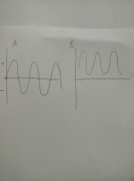
1. They are noisy. Output noise is measured in mV p-p.
2. They are slow, the bandwidth under which they do their thing is about 2 kHz. Above that they stop being regulators, and let the noise through, too.

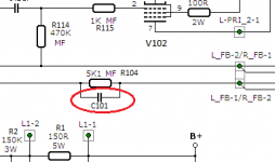
As far as their primary functions of removing ripple voltage and keeping the output voltage constant, however, the work just fine. Furthermore, the output capacitor nicely covers for the regulator at higher frequency. However, we have to start from somewhere, so we'll accept that a better regulator will have wider bandwidth and lower noise.

It's been rattling around my head for a while now, and actually I'm pretty sure I floated the idea here some time ago, but I'm actually going to go ahead and try it out this time: namely, try using the same OP27s used in the phonoclone circuit to also provide a low impedance, low noise power source for that circuit.

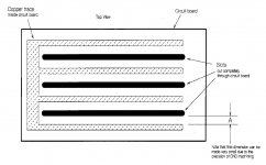
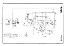
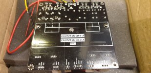
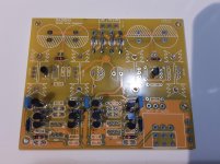
Since playing around in Eagle is easier than actually soldering stuff on the bench, I've gone ahead and designed the new board. Full size 16x10 cm, and double sided with a full ground plane, just like the old BE boards. The next step is to prototype the regulation unit and measure it to make sure is does actually work as advertised. After that I'll finalize the board and order it from Olimex.

If anyone wants to join me at the guinea pig stage, you are welcome to drop me an email. I'll order extra boards and send them out to you, at cost.

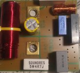
Anyhow, without further ado, here's what the new beasties look like:

both layers shown
An externally hosted image should be here but it was not working when we last tested it.


bottom layer (signal trace)
An externally hosted image should be here but it was not working when we last tested it.


Eagle brd and sch files attached.

regards,

/rjm

Attachments

Sound effects DIY?

Hi

Do you know about any (cheapo...) kits/schematics/projects for a standalone sound-effects for DJ'ing?

Modern DJ-consoles and CD-players often contain effects like "jet, Wah" Ect..

Please see the attached for details on the effects on the CDJ100 from Pioneer.

I suspect that a single standalone chip can do it all?

Kind regards TroelsM

Attachments

  • CDJ100-effects.PNG
    CDJ100-effects.PNG
    268.2 KB · Views: 289

Oscilloscope Safety

I am a new owner of a Rigol DS1054Z scope and a BK Precision 4003A function generator. I am working on learning how to use these instruments without damaging the equipment or myself.
1) Should I purchase an isolation transformer to plug the DUT into?
2) Should I purchase a differential probe setup
2a) Can I use the differential probe set for ALL of my measurements?
3) Should I do both 1 & 2 of the above?
4) Finally, I have built some of my equipment with the audio bus grounded through a pair of diodes, a capacitor and a 5 ohm resistor. Does this arrangement change how I should measure/ground things.

In addition to the usual measuring of low voltage stuff, I would also like to look at PSU ripple of my tube equipment.

TIA

2-Way with two different in parallel

Hi Members
I am new to diy projects. I built a sealed enclosure with
Peerless SDS-830656 few year ago. I have this kenwood
S-511 3-way vented without crossover(all parallel)which was stripped down as the mdf was in bad condition, very old though but the woofer, tweeter and midrange in perfect condition for a rebuild. The internal Vb is around
14 liters with a 10mm mdf. The woofer is 165mm and effective cone diameter is around 128.5mm, the magnet diameter is around 60mm and the mounting depth is around 61mm. The woofer, tweeter and midrange are all surface mount, the max PE is 70 watts per channel.
I would like to couple this woofer with peerless 830656 in parallel for a sealed enclosure. Since, there are ts parameters available for kenwood woofer, can I use peerless woofer as reference. What will be the internal vb for sealed enclosure for these two woofer and a tweeter with a 4 inch diameter.?
Can I build this cabinet without crossover? If not what
crossover point should I use? The fs of my tweeter is
around 1300hz.
Thankyou

STK30x2-III based DIY amp

Take a look at the datasheet for the STK3042-III, STK3062-III, and STK3082-III. These all the same part except spec'd for different voltage rails.


It's a complete stereo power amp frontend on a chip. It has current sources for the LTP and VAS, a current mirror load for the LTP, and a cascoded VAS.


Unlike most other STKs and single-chip amps, this one is externally compensated. You could apply TMC, TPC, or lead-lag compensation, whichever is your favorite extra-deep-NFB arrangement.


I'm thinking this could be the basis for a compact, low-part-count, super high-performance amplifier.


There are questions: is there a reliable source for these parts? Does Sanyo/ON semi ever make batches of new ones anymore? Are there other externally-compensated amp frontend chips?

seeking anyone who's well versed in microsoft windows 10?

Is it safe to power off a laptop right after uninstalling windows 10? Not during a process, the uninstall is 100% complete. Its waiting for the command to begin the installation.

Knowing would be a giant help. After that Ill take it for a new screen then successfully finish the task my dog interrupted while I went to brew coffee.
She tripped on the cord and pulled it clear off the desk. It resulted in a cracked LCD. Only the right side is visible now. The left 50 is mostly white. With a bunch of coloured lines. Rendered useless to me atm.

Like someone once said, $7!t happens. I can't be mad at her for being a dog. Plus shes too cute. I couldn't even begin being mad at her 🙁

Thanks in advance.

Electrical Noise from Heatsink Fan Near Amplifier

Hi folks,

Has anyone had trouble using fanned heatsinks to cool power amplifiers?

In the process of designing a class D amplifier using the TPA3221 IC.
This will be set to 18dB or 24dB gain dependant on SE or balanced input.
The power output can be up to 40W for dual channel into 3ohms. Heat dissipation of 15W max for my application.

Evaluation board (EVB) uses the passive heatsink ATS-TI10P-563-C1-R0. This would be sufficient for my design but it costs money and I have a load of fanned heatsinks. They are sufficient for the heat dissipation and similar to this one. The distance from fan to IC would be around 4mm.

RP64-low-heatsink-fan-1.jpg


I'm concerned about electrical noise being coupled into the amplifier. At audio frequency, magnetic coupling is mostly likely, especially being so close.
A 10mV noise voltage would be amplified to around 630mV for 18dB and 2.5V for 24dB. Into 4 ohms, 10mW only for 18dB but a massive 1.6W with 24dB gain.

Am I overthinking this or have you fallen over the same issue previously? I couldn't find information on this by searching the forums.

Thanks

Problem with low volume Adcom GFA 545 II. Pre amp needs turning way up

Hi

I wonder if you may be able to help?

I have run my Adcom 24/7 for the past 3 years, generally on back ground music which used to be pre amp volume setting of around 8 - 12ish and every now and then turn it up 🙂 to pre amp volume of around 20 - 30ish ( you had to raise you voice to be heard) did not need it any louder than 40 as things would start to shake or vibrate in the house.

However over the last few years I have gradually but noticeably been upping the pre amp volume, just now I was turning it up from 25 (background) volume to 90 and it was not exactly loud at 90 pre amp volume!! 90is the loudest the pre amp has ever been when plugged in to the Adcom.

I changed out the pre amp about 18months ago so I am assuming its the Adcom

Any thoughts as to what may need checking?

Oh! the sound quality remains Good 🙂 from low to higher volumes, which surprises me as I would have thought if something was wrong the sound quality would go..?

Please keep any suggestions basic ;-) as I am a beginner with electronics.

Many many Thanks for any thoughts.

Cheers
Mark

AC motor drive from single-ended supply

Can anyone explain this to me? It's probably a really dumb question!

The schematic shows the motor drive for the Thorens TD320 turntable. the motor is 16V AC. The power supply is single ended 18V.

My question is this. The supply to the motor needs to be as in diag A, so going from + to - does it not? But if the power supply is +18V the supply to the motor will be like in diag B. In which case, how does that run the motor?

Attachments

  • IMG_20210226_092234.jpg
    IMG_20210226_092234.jpg
    237.2 KB · Views: 181
  • Thorens TD300 series service manual-page-011.jpg
    Thorens TD300 series service manual-page-011.jpg
    257.6 KB · Views: 200

3e Audio 3215 3 channel

Purchased from 3e ebay store whilst they had stock. Unused. I also have their 3255 2 channel and I planned on building a 5 channel amp but I am happy with the 2 channel doing the front end only.

£50 posted UK...all other areas please ask but it won't be expensive.

Attachments

  • 20200721_065749.jpg
    20200721_065749.jpg
    801.7 KB · Views: 165
  • 20200721_065759.jpg
    20200721_065759.jpg
    956.6 KB · Views: 186
  • 20200721_065836.jpg
    20200721_065836.jpg
    845.4 KB · Views: 160

Aleph transformer noise.

I have build dual mono Aleph amplifier and have problem with transformers noise.
The noise comes from the transformers and not from the speakers, amplifier sounds wonderfull. If i disconnect amplifier board from PSU the noise disappear.
Each channel draws approximately 130 watts and i have 300VA transformer per channel.
I load the transformer with 160w on another PSU and resistors and it was silent.
Any advice what to check?

DMM: 1KV - Extech vs Beha-Amprobe

Hi,

I'm on the look for a new multimeter. I currently have a very cheap Uni-T that has served me well for many years, but as I have started to service tube amplifiers, I need something that can withstand higher voltages.

There are several to choose from, but in order for it to properly replace my current DMM, I have a couple of requirements:

Voltage: 1Kv+ (current tube amp I'm working on has 700V AC on the transformer)
Current: 0.1µA (very practical when trying to measure capacitor leakage)

Apart from that, the standard: resistance, voltage, current and diode testing. I already have an LCR meter, so capacitance etc. is of no interest.

My budget is limited, EUR/USD max would be 200-250, but lower is very nice.

Currently, I've found two candidates:

Extech MM750W (https://www.elfadistrelec.no/Web/Downloads/_t/ds/Extech-MM750W-eng_tds.pdf)
Beha Amprobe HEX110-D (https://www.elfadistrelec.no/Web/Downloads/_t/ds/HEX110-D_ger_tds.pdf)


These two couldn't be more different, really. The Extech has all kinds of fancy stuff; True RMS, bluetooth, etc and good specs. I'm not sure if I need true RMS, but whatever.

The Beha Amprobe is way simpler, what-you-see-is-what-you-get. So naturally, I'm wondering, would I regret buying the Extech? I can't find much info from users, except some quality complaints, but that was in 2014.

Beha Amprobe seems to be higher quality, but then again, I don't know.

I've also had a look at Beha-Amprobe HD110C (https://www.elfadistrelec.no/Web/Downloads/_t/ds/HD110C_eng_tds.pdf) - it's more expensive, and no auto range, but can handle 1.5Kv DC - not sure if that's any point, however.

Although these are my current needs, I do envision the new multimeter to live with me for many more years.

Do you have any experience/opinions?

modular "everybody" stool

Mod ll.
The wooden everybody stool has 101 purposes. Modding them is so simple I can do it. Drill and tap carbide studs with spikes, instant studio monitor stand. Thats sturdy, mods are simple reversible and effective. Ill demonstrate.

I used them for everything from HL Harbeth stands to thorens turntable stands. CD player. Anti vibration, and, nothing skips on it.

Best of all easy to modify.

I have heavy and light guage stainless, for corners, and sheet. copper, carbide. Metal is delicious, working with it, since I was 12 my mom put me to work turning brass. It got in my blood I guess so. and stayed.

I'm limited to hand tools now. I might have one piece water jetted.


In a pinch these are trusty stand ins, get it stand ins 😉 :yuck:
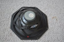
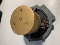
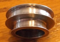
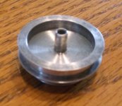
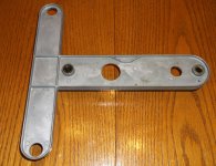
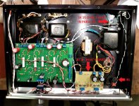
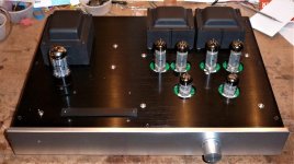
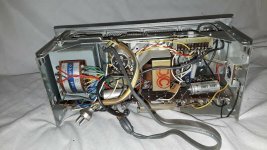
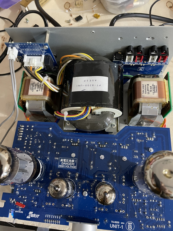
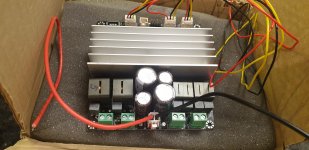
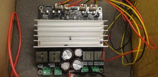
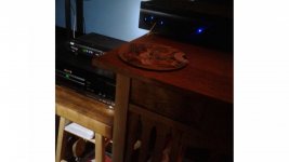
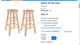
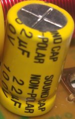
. When your experimenting a new component where do you usually put it, on a pile of something precariously that doesn't belong, or the floor. Because you dont have one of these :cuss:

Excuse my messiness. I was exampling where I will fill the corners. All high grade stainless for bling purpose only. It will get brush finished in the end 😎

Attachments

  • 20210220_103746[2819].jpg
    20210220_103746[2819].jpg
    876 KB · Views: 106
  • 20210226_212602[2925].jpg
    20210226_212602[2925].jpg
    377.4 KB · Views: 103
  • Screenshot (873).jpg
    Screenshot (873).jpg
    55.4 KB · Views: 127
  • Screenshot (872).png
    Screenshot (872).png
    449.3 KB · Views: 108
  • Screenshot (868).png
    Screenshot (868).png
    350.4 KB · Views: 119

DSP + ClassD ~ Hypex Alternative?

Hello people,
I have invested myself in a 2-way speaker design which uses a horn compression driver for upper midrange and high frequency. Because of the physical offset due to the horn of several centimeters between woofer and compression driver, the time alignment is rather difficult, not to say not really possible without ... a DSP function to calculate a delay. This is why I turned towards the idea to get myself two Hypex Fusionamps. For upgradeabilities-sake, I was thinking about FA123 (3 channel, only using two both woofer amps in bridge-tied mode). But my budget finds 800 euros for amps alone is quite a sum, rendering the whole speaker project less a entry level approach. Some very good high end entry level speakers and amp could also be obtained for the same money. Yet, I want to stick to the topology.

Is there any knowledge of performative alternatives? I could get myself two Behringer A800 and a MiniDSP 2x4 used for 350, but I think the A800 has some hollow sounding mids and the MiniDSP 2x4 was tested with intransparent performance. Are there other option out there that I do not know of yet? If not I will probably stick to the Hypex option, but maybe I have missed something.

All the best
Marinus

Modifying speaker crossover

Hi All,

I have a pair of speakers with the crossover as in the attached drawing.

I feel/hear that there is kind of a "hole" in the midrange band (at about 1-4khz), looking at the drawing and placing it's values in few crossover simulators (online) it seems that the crossover point is at about 1.8khz (1.5khz according the speaker spec sheet) and there is a big "suckout" around the crossover point (-12db).

I don't want to re-design the original crossover, just maybe to improve it a little, I noticed that by changing the value of the 36uF capacitor (according to the simulator) in parallel to the woofer to 3uF improve this "suckout" from -12db to about -7db and the crossover point is now 2,290hz.

Does anyone have an idea why the manufacturer chose to put 36uF capacitor (considered as a large value) across the woofer? beside the crossover point does it has any other effect on the speaker performance like phase shift or something else?
According to the label on the back of the speaker the speaker has 8 ohm impedance, I measured 3.3 ohm resistance across it's binding posts.

Thanks

Attachments

  • RP-500M.jpg
    RP-500M.jpg
    28 KB · Views: 451

Anyone know this pcb?

So I built a few amps a few years back. I had a great deal of fun but found myself with less and less time to mess around with things. I recently discovered a board that I had bought and never finished. I spent all day trying to figure out what it is online and failed. If anyone recognizes what it is please let me know. Thanks!!!

Attachments

  • 1614395731650443734484482494037.jpg
    1614395731650443734484482494037.jpg
    593 KB · Views: 196

chario silhouette 100 crossover recap?

Hi guys.
I got these Italian speakers for 150$. They are about 15 years old now (if I am not wrong).
Box build is very sold and nice. Drivers are less nice as I understand.
Woofer basket is made of plastic 🙂 Tweeter is really small thing, not impressive. Can post pictures if you want.
I am trying to get out of them the best they can give.

Currently they sound like some high frequencies are being played through woofer (some dull muddy sound) and not through tweeter as they should. I connected tweeter from other speaker and got the same result. I get such sound on both speakers, not on only one.

I don't think these Chario guys released such sounding speakers to market, so I guess there is some problem with them and problem is located in crossovers.

As I know first thing I can do is just go and recap them both. Sounds like a simple job for some of you, but not to beginner like me 🙂

I took crossovers out without a problem, but I am having troubles on identifying components and their values.

So I need to get:
1) List of capacitors with their values.
2) Any advises from you if I should use some better components then currently installed (almost generic) ones.

Thanks a lot!

------------------------------------------------------------------------------------------------------------------------------------------
Update to summarize the thread:
We decided not to touch any of capacitors except yellow one (bipolar electrolytic capacitor 22uf 100V).

Currently I replaced old yellow capacitors by ELNA RDB 100V 22uf bipolar right now.
Sound seems OK to me.
All modern low loss capacitors (MKP or electrolytic capacitors) are not relevant here.
They kill the bass and spoil mid range. We need to have high ESR electrolytic capacitor here (preferably old designs).

If someone is going to do such replacement for this speaker (or for other Chario), then please try to go with capacitors similar to
ELNA RDB (this is new model available to purchase):
https://hfc-fs.s3-eu-west-1.amazonaw...a_rbd_data.pdf
OR ELNA CERAFINE bipolar (old model which is not available to purchase):
http://www.elna-america.com/products/pdf_files/AL/ROA.pdf


Post updates here on your experience of replacements to any other kinds of capacitors. I will be glad to read.

Attachments

  • Clipboard01.jpg
    Clipboard01.jpg
    400.6 KB · Views: 431
  • Clipboard02.jpg
    Clipboard02.jpg
    398.7 KB · Views: 318
  • Clipboard04.jpg
    Clipboard04.jpg
    150.9 KB · Views: 290
  • Clipboard05.jpg
    Clipboard05.jpg
    163.6 KB · Views: 305
  • Clipboard06.jpg
    Clipboard06.jpg
    598.8 KB · Views: 323

NP-100v12 Build

I recently build a hybrid headphone amp from NP-100v12: DIY 12AU7 (ECC82) Tube / IRF510 MOSFET Headphone Amplifier .

Currently, I am combating a hissing noise that increase in volume as I turn the pot. I have built a LM317 regulator for it. I also have used an SMPS, but still have noise. The difference is, using the linear PSU the noise is a hissing noise which increase in volume as I turn my pot, while using the SMPS the noise is a constant humming noise.

The tubes in it is a 12AT7, which based on the original thread is compatible for this amp. What could be the problem in my build? Your help is appreciated

Also, can I use this amp as a preamp/buffer? If so, do I need to change something? Thanks!

Radio Shack Mini amp substitute

So the RS Mini amp has been MIA for years and only expensive old-stock on FleaBay... I mean $60 isn't going to break me, but then I came across this mini battery powered guitar amp sold at Guitar center for $23. Reviews seem good and I watched some videos on youtube about it.

Any comments on this thing as a suitable replacement for the old RS Mini Amp as a testing device for hobbiest amplifier service (Car audio amps)?

Honeytone N-10 Guitar Mini Amp Black | Guitar Center

8 years old electrolytic caps from DIGIKEY

A word of warning (especially if you have to pay taxes if you are not in the US) when buying electrolytic capacitors from DIGIKEY. I bought Nichicon capacitors with the date code B1311, this is March 2013, the capacitors are 8 years old now. After 3 years they start to deteriorate if they are not used. 8-year-old capacitors should be wasted and not sold as new.

I called DigiKey Europe's customer service and described the problem. I got the answer: why did you not ask what is the production date? What? Really? I should ask about the date of production of every electrolytic cap I am buying? This is very disappointing.

TS Pyramid PB-400a with STK4040XI

I got this Pyramid PB-400a which uses STK4040XI chips. Power Supply works when the rectifiers are pulled and outputs a healthy +40V. When the PS is connected, it oscillates on and off and a pulls heavy amount of current.

So question is, how do I troubleshoot whether the STKs are good or not?

If they are bad, I'm gonna send it back to the seller for refund, or at least try and get most my money back and see if I can find replacements.

TIA!
Tristan

Pro Audio line level interfacing to Home Audio line level: level and/or imp mismatch?

A typical and very common example would be using pro audio electronic crossovers, cheap and readily available, in home audio systems. Let's say, a pre-out in an integrated amp feeds a pro crossover, and the pro crossover then feeds home audio amps.

What troubles me is knowing that the pro electronic crossover is designed to work with stronger signal levels than the home audio gear. The crossover is expecting a stronger input signal than the home audio preamp can deliver. And the pro crossover is outputting a stronger signal than the home audio amp is designed to handle.


Below are comments relevant to my question, quoted from "Sound Reinforcement Handbook" 2nd Ed, 1989 by Gary Davis and Ralph Jones

"...line level phono jack inputs and outputs are intended for use with high impedance equipment, which is basically sensitive to voltage rather than power, so their nominal levels may be specified as -10dBV"

"Typical line level XLR connector inputs and outputs are intended for use with low or high impedance equipment. Since older low impedance equipment was sensitive to power, nominal levels were often specified as +4dBm or +8dBm, levels characteristic of sound reinforcement and recording..."

"A low impedance line output generally may be connected to higher impedance inputs without much change in level. Be aware that if a high impedance output is connected to a low impedance input, that output may be somewhat overloaded which can increase distortion and lower the signal level, and the frequency response may be adversely affected. In some cases, the equipment could be damaged....."

<end quote of Sound Reinforcement Handbook>


Would not connecting the pre-out of an integrated amp to the input of a pro electronic crossover be what is described in the last two sentences from the book, quoted in bold above?

Is using a pro electronic crossover with home audio amps and preamps, even though a common practice, less than ideal and potentially degrading sound?

FS: NEW CDA 120 Class D Audio Kit with Tranny

SOOOOOOOOOOOOOOOOOOOOOOLD!


I have a new CDA 120 Class D Audio kit. Boards in mylar bag and never used or molested. Antek tranny in box unused.

x1 CDA 120 amp board

x1 power supply board with beefier caps

x1 Antek tranny shipped from Class D Audio

Asking $75 and you pay actual shipping. Should fit in USPS Large Flat rate box at approximately $13. Please add 3% for PayPal. I'll take USPS money order as well.

Nick

new project: TD124 with the Papst motor

papst_1.jpg


After seeing Volken's page on cap tuning the Papst motor to work smoother in a TD124 I thought I'd give it a try. If the cap tuning doesn't quite get me where I want to be I'll resort to finding a 3-Phase motor controller and putting that to use.

But first I need to build up this TD124. SN 13943.
DSC_0512.jpg


The original paint on this unit was less than acceptable. So I decided to refinish it. First, I used Aircraft Remover to chemically strip the paint off. Aircraft Remover (yes it is the product name) is popular among automotive painters and also aviation painters. Good stuff.

More info here:
13943

-Steve
Projects by fanatics, for fanatics
Get answers and advice for everyone wanting to learn the art of audio.
Join the Community
507,774
Members
7,887,977
Messages

Filter

Forum Statistics

Threads
406,210
Messages
7,887,977
Members
507,774
Latest member
pete2000