dear to all the team ,
i would like to ask you if i can change the circuit of this amplifier and put another 2 or 4 final transistors Mj15015j ( equivalent of 2N3055).
i attach you the diagram of the amplifier .
how was the circuit ?
thanks
i would like to ask you if i can change the circuit of this amplifier and put another 2 or 4 final transistors Mj15015j ( equivalent of 2N3055).
i attach you the diagram of the amplifier .
how was the circuit ?
thanks
Attachments
Last edited:
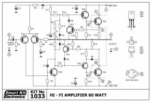
Changing the output transistor type or adding more pairs only has the ability to increase output current but won't change the power until the speaker load impedance is also reduced to use that extra available current.
If you want more power into the same speaker load, you will need power transistors with higher voltage ratings than that circuit was probably designed for. It looks about the same as many generic designs from 50-60 years ago when 40W/8 ohms or 60W/4 Ohms was thought to be high power.
The transistor types are not specified but if you wish to adapt that Smart-Kit design, the transistors and other components will have to be changed to suit higher supply voltages such as +/- 50V or more. That also means a larger transformer and voltages, capacitors heatsinks etc. It would be much better though, to use a more modern design for say, 120W/8 ohms from the outset. It will be more expensive and even doubling the power won't sound all that much louder but if you are a beginner and only want bigger power numbers, then use the appropriate design from the start. Messing about and modifying old designs and component types may give you a working amplifier but its unlikely to be any practical improvement on the original.
As an example, a design known as Symasym here, is available in kit and PCB form and is shown on several websites, in several versions up to Symasym 5.3, I believe. It's relatively simple but quite powerful and uses modern parts - maybe its more like you need rather than what you want but that is matter of understanding what audio power and our perception really means.
Short answer: you have a good and powerful amplifier, leave as is.
If anything, try to improve your speakers, they are the real bottleneck.
If anything, try to improve your speakers, they are the real bottleneck.
Actually Peavey gets 150 W out of a MMA-81502 with +-41 rails. they use a step up transformer for 8 ohms, 150 W on 4 ohms direct. 2 pairs output transistors and a fan.
Ordinarily limit of budget amps of 1970's was heat sink & transformer. Can transformer put out more amps? My 6.75 amp 70 v transformer is about 6"x6"x4". Smaller transformers probably are lower in wattage. Heat sink for 2 transistors needs to be about 13 cm x 6 cm x 3 cm with lots of fins. Unless there is a fan.
If you double up on output transistors, drivers need to put out more current. 1970 drivers were pretty wimpy, but there are ones now like MJE15028/29 with lots of gain at 4 amps. Those will need heat sinks of their own. Then there is the question of whether your circuit board will carry 4 amps.
TO5 transistors tended to be 1 amp design in the seventies. TR1 & 7 could be limitations. Gain really fell off at 1 amp rating. There aren't EBC designs that are more powerful; TO5 became extinct about 1978. Nearly every transistor later was ECB. Allen used 2n6715 and 2n6726 that were ebc with little heat sink surfaces, but the subs for those all have the heat sinks deleted by helpful slugs like NTE & Central semi.
I don't know where you live, but you might be much happier buying a 120 w ch amp like a PV-4c or 240 w/ch PV-8.5c for parts or repair, or even working. I got a PV-4c for $40 with freight needed output transistors and rail caps. After that was stolen I got a M-2600 75 W/ch for $150 with freight. The latter was working. There are various crown equivalents, I don't know their line as well because they are more expensive than Peavey's on the ebay market. don't buy a crown DC300a, they are designed to put DC on speaker, which can destroy one.
A set of 101 db 1W1m speakers makes a 60 W/ch amp sound like a 80 piece orchestra or a grand piano, but used ones of those like my stolen SP2-XT run about $300-600 each plus freight. Trying now to reproduce those in a very ugly package that won't have any value to a fence. Couple of naked 22XT horns for $160 with freight is a great start. Those sound great 1200 hz to 17 khz.
Last edited:
If you are using that amp circuit, on that supply voltage, doubling up on output transistors will make it sound better on 4 ohm loads. Won’t put out any more real power, but distortion (and safety factor) should improve. Those old MJ15015 transistors don’t have very high gain to begin with, and a higher currents it really falls off fast. That makes life difficult for the drivers and increases distortion. Beefing up the drivers as Indianajo suggested also helps, but doubling up on outputs makes this less of a necessity, and the original drivers probably have less capacitance.
More modern circuits such as the Symasym suggested above would measure better. Whether you would prefer the sound is personal taste. You might not even tell much of a difference, depending on how picky you are. Your circuit is much like the Destroyer X which has been quite popular. It too uses a tail resistor and regulator diode for the diff pair tail and boot strap drive. This particular combination when properly implemented does sound pleasing. It’s also very trouble free and tolerant of using different output/driver transistor arrangements. If poorly implemented it can however, sound quite terrible. For example, R3 and R5 must be carefully chosen, together, to balance the current between TR1 and TR2. Get the balance too far off and all hell breaks loose. YUCK! Nail it, and you’ll sit there and go, “I made it do that?????” with your eyes wide open and jaw dropped to the floor.
High efficiency speakers will make a small (in my world) amp like this sound much “bigger” of course. You’re not going to fit speakers that are 100dB/w and make it down to even 60 Hz in something the size of a coffee can. Want high efficiency speakers you’ve got to have room for them. And I personally wouldn’t be satisfied with something like those Peaveys - I would end up doing a custom design using components a notch or two better and proper measurements. Your mileage would certainly vary.
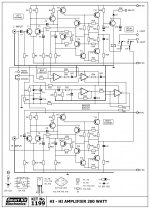
Circuit post 8 has more features, but is very similar. TR17,19, 18, 20 are VI limiters which sort of protect the output (feebly) if the speaker wire is shorted. TR21 is a thump on turn on eliminator. A couple of extra transistors could have turned it into a DC detect and disconnect speaker circuit, but that would cost $1 more. Burning a set of $600 each speakers is a serious disaster if one trips over the 1/4 phone plug on stage and pulls it part way out, causing a short.
All the op amps are a bridging circuit, which is kind of superfluous for a 50 W/ch amp. You want more watts, buy a higher wattage transformer and MJ15003/4 or MJ15024/25 output transistors and a bigger heat sink. More sound, fewer parts. 2n3055 were great for 1970, pretty feeble, by 1980. I've worked on 100 w mono Allen S100 amps (1980) that had a pair of MJ802 quasi comp output transistors, and a heat sink about 6"x6"x6" with about 50 fins. Serious real 100 W, 24/7.
BTW the Peavey SP2-XT and SP2g are the only speakers I've heard that can sound like a real piano. I live in flyover land, anything better looking and accurate is 1500 miles away in Boston or LA. Houston didn't even have Altec Lansing Voice of the Theaters, except in cinemas installed by people from the coast.
Last edited:
You posted 9 while I was editing 10.
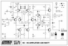
Circuit post 9 gets you away from 2n3055 which is a good thing. Full complimentary helps HD in the 3rd digit.
Q11 & Q3 are CCS which allegedly can drive HD down from .06% of Apex AX6 to .003 %. Can you even hear the .06% of AX6 on speakers? I don't think so. .003% is great for bragging, but not necessary for listening IMHO. I've only seen one speaker datasheet that even charts HD.
Circuit 9 actually has an inductor series the output which is necessary to keep radio from coming in from a long speaker cable. All these designs need that. It also has a zobel c8 r13 to prevent the amp from oscillating if connected to a capacitative speaker. Circuit 9 is still missing the 47 to 120 pf input cap parallel R12 to kill radio from coming off the RCA cables from the preamp. (all these amps are missing that).
BD829/830 look up the Ft yourself. if 6 mhz like the TIP31/32C I used at first, the highs will be missing from the output. 30 mhz MJE15028/29 work well. MJE15028 also works for VAS, which is probably why my AX6 doesn't have any trouble driving MJE15028/29 for drivers.
Circuit 9 doesn't appear to have any feedback to Q5, which is extremely weird. Feedback is what linearizes exponential transistor response.
Are these kit boards you can buy in your country? I thought at first you were upgrading an old amp. You want a kit with significant power, buy a honeybadger from diyaudio store. 150 w/ch with enough transformer & heatsink. Honeybadger takes a big chassis though. I can buy a whole blown Peavey amp for less than one of those custom chassis off ebay with additional heat sinks. Using salvage parts from PC's etc I replaced 134 parts in a PV-1.3k I bought for $55 for less than $120. 650 W/ch 4 ohms. Output transistors, emitter resistors, mica washers, drivers, predrivers, op amps VI limiter input caps were new.
Last edited:
I’m betting those BD829/30 are somewhere in the neighborhood of 50 MHz fT, give or take a factor of 2. Looks like a TO-202 case. Those are long gone, but most types in that case tended to have fT’s that were fairly high for the day. KSC2960/KSA1220 is what I’d use now. More like 100 MHz fT, and reasonably low output capacitance. That’s the reason I don’t like MJE15028 for VAS (Q2 in latest schematic). The higher capacitance doesn’t bug me as much as the nonlinearity of that capacitance. C2, a linear capacitor, is supposed to swamp nonlinear changes in VAS transistor capacitance. If the latter is too big, that doesn’t happen.
That last schematic also uses darlington output transistors instead of outputs and discrete drivers. It’s a double edge sword. It’s simpler, easier to build, but in practice you will never get the crossover distortion as low as a proper EF2 or even QC output stage. You can minimize it but you have to run the bias current much higher than you would normally want to, requiring bigger heat sinks and risking thermal run away. The problem is the connection (and the values) of the internal base-emitter resistors are just plain wrong for audio amps. If I were going to choose which one to build it would be the first one, perhaps with a complementary output stage. With all the “refinements” of the 3rd one, in practice it won’t be any better and both are at the mercy of current balance in the input diff pairs.
That last schematic also uses darlington output transistors instead of outputs and discrete drivers. It’s a double edge sword. It’s simpler, easier to build, but in practice you will never get the crossover distortion as low as a proper EF2 or even QC output stage. You can minimize it but you have to run the bias current much higher than you would normally want to, requiring bigger heat sinks and risking thermal run away. The problem is the connection (and the values) of the internal base-emitter resistors are just plain wrong for audio amps. If I were going to choose which one to build it would be the first one, perhaps with a complementary output stage. With all the “refinements” of the 3rd one, in practice it won’t be any better and both are at the mercy of current balance in the input diff pairs.
- Home
- Amplifiers
- Solid State
- Upgrade amplifier with 2N3055