Hifonics Brutus not sound

Good afternoon gentlemen, I have on my table a hifonics brutus amplifier, it already came from another repair shop, replace source and output mosfets (irf3205 and irf3710), as well as replace the hip4080 driver, the amplifier turns on, green light, there is no overconsumption , the problem is that there is no sound, the relay does not activate, and even by bridging the relay I have no sound, any idea where to start looking? Thanks in advance.

Will the Amp Camp amp work for my project?

Hello , I am planning to make a MTM 3-way active speaker run by a dsp. Using 4 Dayton Audio TCP115-4 , 2 for midrange in a sealed cabinet and 2 for woofers in a passive radiator cabinet. A Dayton Audio RST28F-4 Tweeter for highs. I'm thinking about using 3 Amp Camp Amp's to run it. I will be using it as desktop speakers. I'm sitting not even a meter away. I'm looking for impact and punch. I know class A is known for great control. Do you this will be a good pairing? also will be my first amp build. The speakers will be paired with a 18" 700w rms subwoofer. And if you see any problem with the speakers please say something too , it's only my second speaker build. Thank you in advance.

Looking for LM4880 replacement for x-fi sound card

Hi, I bought an MS-4132 sound card, which is a custom version of the sb1040 aka sound blaster x-fi audio. It has 5 LM4880M and 1 33078 op amps, but since i don't have pcb schematics, I don't know what's the 33078 used for and why they didn't use another 4880 instead

I've searched for the pinout of the 4880s and it seems different from the lots of op amps on the market, due to a "shutdown" and a "bypass" pin.
Do you know some good op amps I should replace the lm4880m with (and eventually the 33078, as well) or if those are good enough, considering that the sound card is pretty old?

Attachments

  • Capture.PNG
    Capture.PNG
    205.3 KB · Views: 94

B&C DE-250 FRD & ZMA questions

Hi guys i was wondering if anyone had FRD & ZMA files for the B&C DE-250 driver on a Dayton Audio H6512 6-1/2" x 12" Wave-guide. I am wanting to build a pair of econowaves for my churches recreational room. I would love to be able to play in xsim with the files before buying. Right now the room has some no name pa speakers that sound like crap. Thanks in advance

NAD "Shorting/Bridging plugs" query

I had to send my little NAD amplifier in for a repair recently and I took out the little bridging plugs and put them in a safe place. I now can't remember what that safe place is and I can't find them.
NAD Australia want $9- for the pair of them plus $25- postage and I'm wondering if using a spare set of RCA connectors with a short fat wire will work better than the current 600mm length of spare cable I am using to do the bridging between the Pre and Power sections of the 325BEE.
Naturally I could simply pay for postage but I'm a tight-**** and also cash strapped at the moment.
If I solder some up does the conductor wire size make any real difference over 50/100mm?
Also is shielding needed?

Best way of adding multiple device inputs

Hey!

I have a question regarding adding multiple sound inputs to my pretty conventional 3 way sound system using a set of filters. So currently I have one RCA connector for left and right sides connected to the filters. This is fine when I had just one input, but I’ve also got a TV connected too, and I constantly have to switch the two manually. Is it possible to have two rca inputs connected at the same time and switch between the two? I can connect two directly to the filters, but I worry about the static and unnecessary noise. Is there a way to switch off the one that isn’t being used, sort of just choosing which input I want at a given time?

Speaker filters - Album on Imgur

Help with Yamaha C1 power board

I have a yamaha C1 power board. The 100V section keeps blowing a 1k resistor. I have new tip40 power transistors and diodes and caps are new.
Here is the schematic. Far left section, resistor marked R2012 and R2011.
I don’t have an Oscope! Can anyone explain this part of the board? TR 2003 & TR 2004 have been replaced also. Thx Guys

Attachments

  • 27D84EF4-12A8-432A-9B6B-B5926D458803.jpg
    27D84EF4-12A8-432A-9B6B-B5926D458803.jpg
    608.9 KB · Views: 75

passive preamp for pass aca

Mmmokay, i dare to start a new thread – it's a first so please be patient and if anyone could help, I would be much obliged.

My question refers to the choices of preamplification for a pair of PASS ACAs that I plan to run as monoblocks.
Yes, I am aware that there is a thread with a similar topic, but in fact I don't want to go the DIY road with that one.

I use a pair of very high sensitivity DIY horn speakers, with no crossover and a single RFT driver like this one. In horn enclosures they probably have an efficiency corresponding 98db or more.

But the tweaking demon won't relent. Inspired by an article by Chris Templer at tnt-audio I intend to fit these enclosures with a pair of Goodmans Axiom 201 drivers. It looks like I'm not the only one on diyaudio thinking about this combination, there are even some success stories and a lot of interesting amplification advice as well.

Back to my horn loudspeakers are very... well... loud. For example, when driven with a 2x18 watt Audio Innovations i couldn't listen to them past "10 oclock" on the pot. Of course, with the RFT they are 8ohm but as soon as the Goodmans are going in, they become 15 ohm.

I have two music sources:
1. a DAC (the Denafrips Ares 2) with XLR outputs (this model has no volume control)
and
2. a mm preamp (obviously also without volume control).

A passive whichmagee attenuator or external volume control is what I would like to drop in this combination.
I am wondering if you could comment on my choices.

For instance:
this one that is just a volume adjuster or this slightly fancier one Do you have a suggestion which one to chose?
Other versions even have serveral values to chose from (10K/50K/100K/250K/500K).

Any suggestions?

Hafler SE 120 Schmatic Explanation

I have a working Hafler Se 120. I have attached a schematic and I am trying to figure out how the two transistors circled work together. Also the circled 5.1 ohm resistor does get very warm and I am trying to figure the voltage drop and current through it. This 5.1 ohm resistor is 5 watts not 2 watts as listed. This is more curiosity than anything. Thanks to anyone that can help. Mark

Attachments

Weird Port Response

Hello All,

I'm testing a prototype but have some interesting behaviour.

Would anyone have any idea's why I would be getting this weird dip in the port response at the tuning frequency?

Shared album - Billy Jukes - Google Photos

The speaker was sat on the ground and the microphone was located 5cm from the port opening.

This box uses a rear triangular port for other design reasons.

I have tried varying the length but I still get the same dip at the tuning frequency.

The port is only 12cm long and the largest internal dimension of the box is roughly 42cm so I can't see any issues with modes in the port or box.

The box Vol is roughly 25L and is triangular in shape.

The Fs of the driver is 60Hz so I don't see any issues there.

Here's a measurement at 5cm from the port with the same driver in another box with a front, square port of similar area and length and slightly smaller box volume with a wedge-shaped box. No issues in the port response here.

Shared album - Billy Jukes - Google Photos

Any ideas will be grateful

New project : R-2R Attenuator With Remote Control V2

What I Share here is my Remote Volume Control KIT V2.

This is a assembled volume controller with 4 sources selector based on high quality Panasonic TQ2-5V relays.

8 Bits conrol provides 256 STEP variation, with the selected useful 67 STEPs, this attenuator can be adjust from -48 dB to 0 o dB (with a infinite load).
Comparing to my VOL V1, this new version is more friendly to listening.

VOL V1 located here :
http://www.diyaudio.com/forums/showthread.php?s=&threadid=130302


Function & Feature
1. 67 steps volume control without any ¡®POP¡¯ noise
2. 4 sources selector
3. Beautiful LCD display, White code with Blue background
4. Universal remote handset
5. Remote / Manual control
6. Considerate PCB layout
7. 8 PCS high quality Panasonic TQ2-5V relays and VISHAY DALE RN55C resistors
8. Build your balance stereo attenuator easily, you just only need to add another main board
9. Easy to use. Only +5V DC power supply is needed
10. Fully test before shipping


This lit includes:
1. Controller board with LCD display
2. Main board
3. Remote handset
4. Remote receiver , rotary encoder and connecting cables

USER MANUAL is ready to go ^_^
Shipment / Carrier : Hongkong Post Airmail Registered
Payment : Paypal I am a verified Paypal member

Total cost : promotion price is only 65 USD , shipment and paypal fee included

Merry Christmas to all the diyaudio member🙂

best regards
bbp

Attachments

  • dsc05632.jpg
    dsc05632.jpg
    77.4 KB · Views: 4,649

Ground Zero GZNA 2800X PS Trouble

Received this amp with a blown PS section. Removed all IRFZ48V and replaced with STP80NF06.
Rectifiers removed, because some of them short.


Everything else looks ok.
Without recitfiers it pulls high current.
But it seems, that the Fets are not driven good.
Gate resistors are original 328Ohm,
there are no pull down resistors.
I have on each bank a 10 Ohm resistor at the source, with a cap connected to drain.

Attachments

  • IMG_20210308_180539.jpg
    IMG_20210308_180539.jpg
    716 KB · Views: 83
  • IMG_20210308_180619.jpg
    IMG_20210308_180619.jpg
    592.9 KB · Views: 88
  • IMG_20210308_180623.jpg
    IMG_20210308_180623.jpg
    686.5 KB · Views: 91

SSE Power Supply Observations

Since I have the B+ voltmeter and plate current ammeters, it is easy to observe what my amp is doing under any given situation.

What I have noticed is that the limiting factor is my transformer.

I have come to this conclusion by observing my amp running with different rectifier tubes and, more importantly, different cathode resistor values.

The conclusion, based on my observations, is that lowering the cathode resistors to pull more current through the output tubes simply results in B+ sag.

For example: With a 5AR4 rectifier and 620ohm cathode resistors, my B+ sits at about 430V and ammeters indicate ~57mA of current through the tubes.

Same setup with 560ohm cathode resistors (simulation shows B+ remaining at 430V and tube current going up to 63mA) - my meters indicate B+ drops to ~410V and tube current is up to barely 59mA.

I could be wrong - but what this tells me is that trying to pull more current from my transformer is a lost cause. Also, the transformer runs considerably hotter under these conditions!

It's like when you run an engine at 4 thousand rpm and you are already getting all the torque and horsepower vs. redlining it and getting nothing more than extra heat and a much shorter life.

The sound? Zero difference to my ears. I'll be going back to the 620ohm cathode resistors.

Note: I've also learned that SEAmpCAD assumes a transformer with infinite current capability. I like how PSUD2 accounts for the load and adjusts B+ accordingly. It would be nice to have all that functionality wrapped up in one software package.

What is limiting 1" compression drivers from playing <1kHz at "low" volume

What is limiting 1" compression drivers from playing <1kHz at "low" volume

Hi all,

I have a question over how low compression drivers can play.

I am looking at running a 1" CD to sub 1000Hz (lets assume 650Hz for ease of maths) on a horn with a cutoff of 500Hz.

For a driver such as the Faital HF108, it is listed as having a crossover at minimum 1.3kHz, with a power handing of 60w AES. The response plot also shows from 1.3 kHz to 650Hz as a ~3dB drop in mean efficiency (with some ripples happening that low)

HF108_response_8.gif


FaitalPRO | HF Drivers | HF108 (8Ω)

Assuming that this is excursion limited at this power, if I were to drop to 650Hz (and being happy with the ripple in the horn due to cutoff proximity), for the octave drop it would be able to take 1/4 of the power = 15W. Assuming that I then EQ the +3dB in at the 650Hz point, that halves again to 7.5W maximum power.

Because of other limiting components in the system, I can't see the need to exceed 5W (my eardrums included), so would this technically work?

Or, is there something else I am missing? How would it even sound that low?

Plus! Are some 1 inch drivers better suited to this type of (ab)use than others?

Many thanks in advance,

Crossover current by 3WC mkII by Troels, opinions ?

" Some of you interested in crossovers may find the current 3WC mkII crossover intriguing and I look forward to your response. "

Speaker Talk

25th February 2021

This is a recent question from Troels for his readers.
I have experience in assembling boxes, but not in calculating crossover networks. Although today there are programs that help a lot in this task, but, I consider that experience is essential.

So the table is set, you just have to sit down to eat ! 🙂

Conflicting info: LOC VS digital processor for stock system

New to the site, be gentle. I only know enough to be dangerous.

2017 Hyundai Sonata, all stock, with a 9 speaker Infinity system that includes a 8” sub in the rear deck. Not bad, at all, though the sub doesn’t always handle every task. Plan: add a single enclosed Kicker sub using a Boss R1100M mono block amp. I have a Scosche 2 channel LOC (LOC2SL, 80watt).

LOC: LOC90 Line Output Converter | Convert Speaker Wire to RCA

Amp: R1100M | BOSS Audio Systems, a Leading Audio & Video Brand

Sub: Kicker 10” Comp? In sealed truck box

I’ve done this set up before in another car - sounded great. But this Infinity system is amplified, and 12 people have told me 14 different things.

I WANT to posi-tap into the sub wires PRE-amp (via the wiring harness, as I have the Hyundai service manual sheets with pics and wire IDs), but WILL IT WORK??

Of course I have zero idea how much juice is going into those wires before hitting the amp and how it will all pan out.

I’d appreciate some relevant replies, knowing I’m using what I’m using, so I just need to know 1) sure, that should work, or 2) uhhh no that won’t work (and why), and then 3) what I would need to do to make it work.

In advance, thanks.

  • Poll Poll
Symasym vs Mauro Penasa MyRef C


Hi, i am new to the world of DIY amps. I currently have a jadis dp60l preamp paired with audio analogue donizetti monoblocks. I was wondering which amp is better sounding and more worth to build, symasym or myref C. I can get build both with the same price, so i just wanted to know which one is better to build. Thanks!

DIY Speaker help

Hi.


Wondered if someone would be able to help me. I'm looking to convert an older wooden box single speaker into a unit that can house an Alexa device and speakers within it. I'm looking for a simple 2 coaxial speaker kit or order separate components so it can all be housed within the unit, and attached to the Alexa via the 3.5amp jack. I'd look decent quality speakers. But thinking under £30 seems possible?. Would anyone know where I could get these bits. Ideally would prefer not to have to solder


Thank you for any help, Dave

Attachments

  • PXL_20210306_174015384.MP.jpg
    PXL_20210306_174015384.MP.jpg
    931.1 KB · Views: 84

Crikey 250V! Taming Aussie mains supply.

G’day

The Mains voltage here in Northern Sydney averages 250V, the upper end of the supposed 230V nominal range.

I have a 220V rated Yaqin MC5881A it’s always given off some heat but sounds great so no worries, she’ll be right.

Recently I had to replace the volume pot and whilst tracing the fault and conferring with various threads here realised the internal voltages are out if spec.

Secondary 376VAC
B+ 474V
Heater is 7.56VAC

There are a number of recommended internal adjusts on this site. However I realise that I probably need a new power transformer.

1) any other suggestions?
2) how do I best find a suitable spec transformer ?
3 anything else to consider?

Phillip

Book-shelf absorbers?

There are plenty of bookshelf speakers, anyone tried to make bookshelves that act as sound absorbers?
My main sound room is fairly reverberant and some extra absorption would be helpful.
Sound absorbers that double as bookshelves seems like an efficient idea but I haven't seen them, has any one else?

The details are that my room is about 8m x 4m x 3m (not exact multiples) and built on a concrete slab, with concrete brick walls.
Definitely no wolf will blow my house down but the bass modes are pretty severe.
The speakers are on the short wall, 2 subs placed to cancel the first cross modes and vertical modes.
The axial modes are less controlled, the wall at the other end from the speakers is broken only by one door, couple of other doors at that end in the side walls.
Book shelves on the end wall would fit the house layout, I could make it more or less all shelves.
The plan is to make the shelves from steel sheet with a C cross section, the open bottom of the shelf would be used for a limp-mass membrane absorber.
I can fit shelves 200 mm wide, thickness is flexible, maybe 75 mm.
I also plan to install some shelves between the speakers but there's a window so this wall at least has some absorption.
2 extra subs on the far wall is a further option to reduce the first axial mode but I'd like to try the shelf solution first.
The shelves will also provide a bit of extra diffusion and that should help too.
Anyone have any experience or ideas for this?

David

12at7 voltage and gain

Hello,

I built a DIY 12at7 preamplifier.
The tubes run at 12v.
The issu is that the amount of gain is enormous.
The preamp has a volume control on the input but if I run it to a power amp, the gain is such that even the relay cliking on the preamp blows like a bomb (the power amp has no volume control)
In order to use it, I had no choice but to put a dale volume controls between the preamp and the power amp.
This been said, I was wondering if going from 12v to maybe 7 or 8 would reduce the gain or am I condemned to insert a dale between the premp and the power amp?

Thanks

A quite simple bookshelf speaker with the Markaudio Alpair 10.3

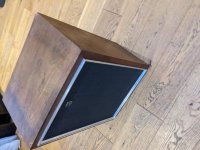
After a long audio absence, I was curious to build a simple vented or closed bookshelf speaker with a fullranger for my office.

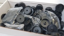
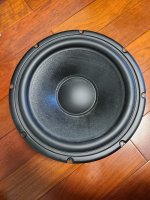
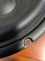
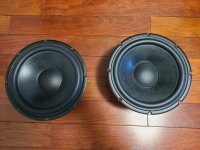
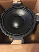
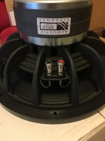
I was lucky to get a pair of Alpair 10.3 cheaply from ebay, so my starting point was this simple box which you can find on MarkAudio's website

http://wodendesign.com/downloads/simpleReflex-103-10p-plan-100214.pdf

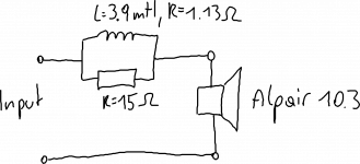
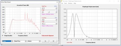
Now putting a fullranger into a small box without any sort of filter won't give a neutral frequency response as the baffle step is not compensated.

While I respect MarkAudio's attitude of avoiding filters, this simple speaker design is pretty much unlistenable as it is all treble, with little midrange and no bass output - which is exactly what happens when the baffle step is not compensated.

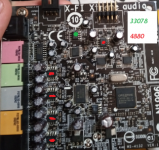
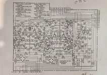
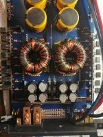
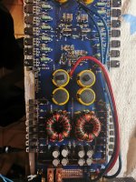
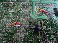
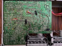
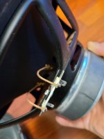
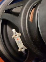
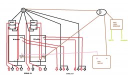
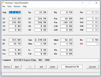
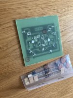
After tinkering, building and listening to 4-5 different filter designs, I settled for a very simple RL-filter which - IMHO - works very, very well giving a neutral, balanced sound. Of course with such a filter one can only burn away energy, so the resulting speaker does not excel in efficiency.

I like the resulting sound a lot and thought I would share it here, so that others can try it too.

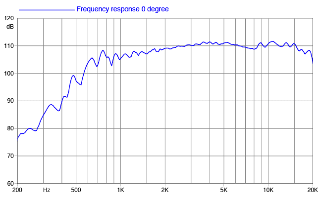
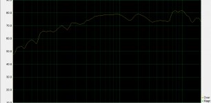
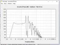
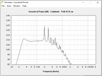
A note on bass: this speaker has decent bass output and I'm personally not missing anything in this regard. I know that the measurement might convey a different picture and one might be tempted to further attenuate mid and high range in favor for more bass.

However, my personal opinion is that full rangers should not carry the load of hefty bass output anyway. The required excursion for low frequencies doubles with every octave going down, which means that the full ranger works at least twice as hard at 50 Hz than at 100 Hz. The result is a strong increase in distortion - which can reach 10% for some transducers. If more bass output is needed I would opt to add a subwoofer and cross it with the fullranger at 100 Hz or so.

As the linked, initial filter-less speaker design is called simple bookshelf design, I termed my variant a quite simple bookshelf design.

Enjoy this little fun speaker, Hannes

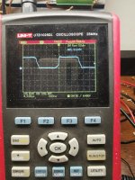
PS: attached is a periodic white noise on-axis measurement 10cm from the cone away, 50 averages taken. My measurement chain is not calibrated, so values might not be fully accurate but should give an impression.

Attachments

  • RLv5.png
    RLv5.png
    75.7 KB · Views: 612
  • quite_simple_bookshelf.jpg
    quite_simple_bookshelf.jpg
    139.6 KB · Views: 599

FS DACT CT2 10K Stereo Potentiometer.

BUMP: FS DACT CT2 10K Stereo Potentiometer. Or Best Offer.

I bought this a few years ago to use on my AKSA pre-amplifier. It has maybe 20 hours on it. I soldered the signal wires and there is a small amount of solder on the connectors. There is also a small boo boo where I nicked the plastic outer case with my soldering iron, this nick is small and does not go all the way through the plastic.

$105 Shipped in Canada and Conus. Or Best Offer.

Attachments

  • 20210306_165827.jpg
    20210306_165827.jpg
    279.7 KB · Views: 266
  • 20210306_165924.jpg
    20210306_165924.jpg
    278.9 KB · Views: 263
  • 20210306_165942.jpg
    20210306_165942.jpg
    285.9 KB · Views: 255
  • 20210306_165851.jpg
    20210306_165851.jpg
    259.7 KB · Views: 252

Post Formatting Issues?

More and more I come across posts which require me to scroll horizontally to read sentences that are 2 feet long. You have to scroll back and forth and back and forth just to read them. I usually get frustrated and just move along.

Is there any way to fix this? I assume it has something to do with the poster, not the reader. None of my posts look like this.

I also see numerous posts where the pics are so large that only a tiny portion of them are visible. Clicking on the pic, which normally enlarges it, actually makes it smaller and, in most cases useful. Again, I suspect this is has something to do with the way the poster is uploading the pic.

I don't recall seeing either of these issues many years ago.

Has anyone modded the onkyo a9555?

I just got an onkyo a9555 and the mids are a little recessed and it lacks drive. The soundstage is huge but diffuse. A guy named bobwire on audioasylum modded his but didn't post pics.

I have a little experience with soldering and modding but I don't think I can do surface mount components. Any help would be greatly appreciated.

Anyone work on one of these? It has a lot of potential and I like the efficiency of digital amps.

Both right channels dead on dual deck JVC KD-W110 cassette player

It's not the cables. Lol. The audio and LED meter for the right channel from both decks shows no signal. Can someone please tell me what to check first? I went ahead an reflowed the solder on most of the IC's. No change. Thanks!!!!

Attachments

  • 1.jpg
    1.jpg
    1.1 MB · Views: 149
  • 2.jpg
    2.jpg
    1.1 MB · Views: 148
  • 3.jpg
    3.jpg
    1.1 MB · Views: 144

FS Peerless SLS 830668 10" woofer pair

For sale 2x Peerless SLS 830668 10" woofers.
Good used condition, old batch (~2011)
Some dust on the cone, light scratches on the frame (see photos), soldered terminals.

$70 / pair or $40 for one + shipping. Located northeast US

Attachments

  • 20210305_132959.jpg
    20210305_132959.jpg
    907.2 KB · Views: 239
  • 20210305_133026.jpg
    20210305_133026.jpg
    424.9 KB · Views: 211
  • 20210305_133032.jpg
    20210305_133032.jpg
    481.9 KB · Views: 207
  • 20210305_133049.jpg
    20210305_133049.jpg
    670.3 KB · Views: 190
  • 20210305_133104.jpg
    20210305_133104.jpg
    363.7 KB · Views: 182
  • 20210305_133114.jpg
    20210305_133114.jpg
    451.9 KB · Views: 79
  • 20210305_133134.jpg
    20210305_133134.jpg
    554.3 KB · Views: 83
  • 20210305_133157.jpg
    20210305_133157.jpg
    478.4 KB · Views: 81
  • 20210305_133338.jpg
    20210305_133338.jpg
    849.2 KB · Views: 88

Smaller Danley speakers for home?

I've got some money burning a hole in my pocket, as my grandma used to say. Rather than p--s more of it away on poor choices in the stock market, I have long toyed with the idea of getting a pair of Danleys for home use. Alas, the biggest impediment isn't money, but the perfectly good pair of Yorkville U15 I've had for about 5 years. These were bought used/cheap and I tweaked them to taste, and actively EQ-ed, they (probably) approach what many DSL speakers could offer, of course, without the latest crossovers and such. "Well then, why are you posting about buying newer speakers if you're not serious?" people may inquire.

Just so. Many of DSL speakers are way overkill for the home, of course. If I had a spare $8K or so, I might spring for the classic SH50. But maybe something smaller. DSL has a range of much smaller unts that might serve well in the home. The SM60M or SM60F is a likely candidate, but isn't all that much cheaper than the monster SH50, perhaps $2500/each. What about even cheaper? On Ebay there is a pair of the oddly named GO2-8CX, for $1600 open box. This suggests perhaps $1000/ea. new -- very close to what the Yorkville U15 sold for when it was new. If you look at DSL's specs for the GO2-8CX, it is impressive for a 8" co-ax. I'm not familiar with "church" or PA type installations. I'm assuming it could be run from a normal home amp (8 ohm). With their smaller speakers, of course you'll lose the pattern control at lower frequencies. But how important is that, in the living room?

So, throwing out the question: has anyone used the really small DSL speakers for home use? They seem like they would be a good fit, if their performance is anywhere near what is claimed for their bigger brothers.

Budget active subwoofer lowpass, buy, eval, mod

I was looking at another low cost filter board, from the far east, to complement my active xo project. Budget active 3 way crossover - buy, eval, mod - diyAudio .

I actually wanted a bandpass more than just a lowpass. I wanted to attenuate the subsonic (<20Hz) as it causes wild movments in some types of subwoofers (BR, BP). In addition to setting the lowpass frequency and gain.

I saw a few different designs and settled on this one (see pic). It costs $8CDN but you have to assemble it yourself. It also has the same problem as all of them, no documentation or schematic. The irony is not lost on me. I bought parts to assembly, from probably the lowest cost assembly region in the world.

I bought this one because:
- it has terminal blocks for connections
- it uses a bipolar supply (see other xo), removes DC offset problems
- appears more complex than others (cap count, regulator, 2 dual opamps)
- potential to modify it, if needed (all through hole parts)

Note : there is a better board at Budget active subwoofer lowpass #2, buy, eval, mod that I prefer over the board in this thread.

Attachments

  • DSCN2558 reduced.jpg
    DSCN2558 reduced.jpg
    538.9 KB · Views: 520
  • DSCN2560 reduced.jpg
    DSCN2560 reduced.jpg
    451.6 KB · Views: 509

ESS Heil Model 400 Power Amp

I recently acquired this power amp with an unknown history but learned through a member on the Audiokarma forum that I might find info on this site. The amp claims 500 watts or 250 per channel, weighs considerably and appears very well built. After cleaning up the exterior I opened it up and found the transformer was loose and some small black plastic pieces were on the bottom of the chassis along with some small but long machine screws. Removed the screws, vacuumed up all the plastic bits, tightened down the bolts securing the transformer, traced those screws to the back of the output meters, sprayed the pots with Deoxit then visually inspected the circuitry for any abnormalities with all appearing fine. Another thing, those heat sinks extend way out and have sharp edges, I've the scratch marks on my arms to prove it!

Powering it up using a DBT with a 100 watt bulb and 8 ohm dummy load per channel with gain pots set at a minimum, the bulb was first bright then momentarily darkened then came back on at about 3/4 the original brightness. there was no Magic Smoke or explosions! That's about all I had time for today but it looks like a promising project.

Found some info on the bias and offset from a restorer online who thought it should be set to 100mv but this applied to the model 200, haven't found much info on the model 400. Do you think the 100 watt bulb is insufficient for testing this powerful amp or should it be a greater wattage? The transformer is massive and rated at 1.5 killowatts, pretty intimidating and approached with caution! I've some info on this and will have to read it carefully before proceeding further but so far don't see any info on how to go about setting the bias or offset, any info regarding doing this would be most appreciated!

Measurements of an Adcom GFA-5800

It's been some time since I've posted here. But I think this is the right question for this audience. I'm just curious if anyone knows of a measurement work up for the Adcom GFA-5800- the sort of thing you would see Stereophile's J.A. doing in the tan boxes in the equipment review. I have the Adcom supplied Audio magazine review, but it unhelpfully omits any details.

Basically wondering what the measured power output into common loads was, and what is the lowest practical impedance it can play into.

Thanks much!

/Mike

JBL 4367 - Setting up for External Crossover

I currently have 4367s and want to start playing with external crossovers, bi-amping, convolution filters, etc. That said, this is my main system and I'd like to maintain the passive crossovers and normal system signal path through my integrated amp as the baseline while I'm not messing around over the next however months (years?!?) doing this.

So I've been thinking about two options:

(1) a custom binding post plate with one set of binding posts for the passive xover and another 4 pole speakon connector that would be direct to the drivers (with protection cap on the compression driver). Then just a simple switch or set of switches to flip between.

(2) pull the xovers out of the speakers and put them in a separate enclosure by the rack and then have one set of cables to the speakers.

Am I crazy, anyone do something similar, recommendation on parts to use, high quality switches? Anything I do the goal would be to not mess with the stock parts such that it could be put back to stock at any time.

Thanks!

Acoustic Elegance SPB12-8

SOLD - Acoustic Elegance SPB12-8

Bought these new from AE in 2016. They are new in the boxes. And when I say that I don't mean except for that one time I hooked them up or when I test fitted them. They have never had a wire attached or even been taken out of the boxes other than looking at them and taking pictures. In fact 3 of the 4 boxes have not even been opened. They are still sealed with the packing tape applied by AE when they shipped them to me.

I've got 4 matching SPB12-8 drivers.

These were supposed to go in a WMTMW of my own design but life happened and I don't know when I will have a place to use the monsters I was planning to build.

Obviously prefer pick up in the Atlanta area but I'll ship them if you pay for it.


All 4 drivers as a package for SOLD

Attachments

  • AE1.jpg
    AE1.jpg
    201 KB · Views: 670
  • AE2.jpg
    AE2.jpg
    238.1 KB · Views: 674
  • AE3.jpg
    AE3.jpg
    170 KB · Views: 680

One Electron UBT-2 Output Transformers - No Longer Available.

Hey all,

I received an email from Bill at Tubes and More (AES) today informing me that the UBT-2 ouput transformer from One Electron is no longer available. They still have the UBT-1 and 3 in stock though.

Bummer, I had very good luck with the UBT-2 and was looking to build another lower cost 300B.

One more good option for a budget output gone. 🙁

$20 to the first person to give me the tip that gets my NAD 3020 working

Here's the deal...

I'm a relatively novice repair tech who knows how to avoid getting electrocuted and can fix most basic problems with audio gear. I've got a NAD 3020 on my repair bench that I'm fixing for a friend that I could use some help figuring out. I'll give $20 to the first person who gives me the tip that leads to this thing getting fixed. (for realz!) I know it's not much, but I'm not making much on it either, so that's the deal. 😉

Here's the service manual and schematic.

Here's the clues:
  • I checked it over for loose components and cracked solder joints. There were a few loose connections, but otherwise (I think) everything's connected properly now.
  • I just put 4 brand new power transistors in it (Q615,Q616,Q617,Q618)
  • FUSE 3 and FUSE 4 were blown and I replaced them with new 3A fuses
  • It turns on
  • It passes distorted garbled audio
  • Turning the volume control up results in more distortion, but not more volume
  • after a few seconds, R643 and R644 start smoking and charring

If you need more clues, just ask and I'll do further testing or take pictures or measurements if you need me to. I just want this thing fixed and OFF my bench! I really will send the money.

Thanks guys!

HELP NEEDED...Noise from a 4 channel B1 buffer with Biino MK2 volume control...

Hi everybody... First of all, please forgive my bad english...
I would ask advice about a nasty hum problem I have from a 4 channels B1 buffer with two Biino volume control boards I built...
I tried various wiring ways to improve but none worked...
The situation now is what (maybe) you can see from the weird drawing here...
Can you see something absolutely wrong that could cause gnd loops or something?
I used a gnd loop breaker between psu star ground and earth/chassis...
Thank you so much!

PS. The Biino is a relay attenuator you can see here:

Biino MK2 – hifi-electronics.de

Attachments

  • BIINOB1.jpg
    BIINOB1.jpg
    174.2 KB · Views: 118

1939 Philips article about dispersion controlling implements for fullrange drivers

I thought this was very interesting. It, amongst other things, exactly describes and shows the device I described with words on here multiple times.
Good to know I am not delirious in thinking it works. ;-)
Basically a very simple multicell horn.

https://www.pearl-hifi.com/06_Lit_A...ilips_Tech_Review/PTechReview-04-1939-144.pdf

Also very, very interesting publication. And a great site PEARL, Inc. Homepage

I’m surprised with how small dispersion correcting modifiers can be and still work well down to 4kHz.
And with how critical exact angle is.

Index of /06_Lit_Archive/02_PEARL_Arch/Vol_16/Sec_53/Philips_Tech_Review

Port Volume Question....

This will possibly be my first ported subwoofer build. I generally stick to sealed for simplicity and to keep the bass tight. Currently looking at a pair of Eminence Lab15 drivers in their "Medium Sized Vented Club Sub" configuration, 2 drivers / 2 cabinets. Distributed bass, you know the drill.

My question is this. They're asking for a 6.5x6.5x21.9 port, which equals 0.535cuft of port volume. If I rearrange that as a slot of 17x2.5x21.75 (0.534cuft), will I be running in to any issues with box tuning? Not sure if a slot reacts any differently than a rectangle port or whatever. Really boils down to cabinet aesthetics and the slot seems to tie in better with the dimensions I'm after.

Link to cabinet: https://buyeminence.com/img/product/description/LAB_15_cab.pdf

TIA all. Appreciate any criticism, constructive or otherwise.

6x9 enclosure design question...

hello all, i have a pair of pyle plx693 3way 6x9's, and i would like to build an enclosure for them. what im looking for is a single cabinet split chamber design to fit in the back of my toyota ext. cab truck. i was thinking .60cuft sealed or maybe .90 vented. the idea is to get low bass with out having to use subwoofers. this is my work truck so no need for any.
now what i would like to know is...

1. would you ppl recommened bigger enclosures? if so, how big?

2. vented or seald? if vented, how big (DiaxL)?

3. how much fiberfill would be recommended to reduce standing waves?

the idea in my head say's a .90cuft with a 2"(d)x5"(L) vent, half filled with fiberfill would sound great.this enclosure will have different speakes in them at times, i plan to install my 2ch soundstream amp to drive some bigger 6x9s when i get them.

any input would be great thanx

[DIY] Two way mono speaker

Hi all!

I would like to built a two way mono speaker for my daughter, to use during the birthday party or others events.

My idea is to build a single, relative small high power two way speaker with an integrated amplifier.

For the moment I have build only full-range speakers (One DCAAV and one TABAQ), therefore I have no idea how to build a multi-way speaker.

There are some guides? I have many questions:
- How choose the drivers?
- How set the distance between the driver? How to choose the drivers positions on the baffle?
- The tweeter need a separate chamber or not?
- How to dimension the cross-over frequency and how to equilize the "gain"?

For the woofer I have find the FaitalPRO 8FE200 4Ω, seems that works good in a 20L bass-reflex box and then can handle 130W RMS with an high efficiency (95dB).

The amplifier that I have found is the following:
ICEpower 200ASC Class D Audio Amplifier with Power Supply Module 1 x 200W

Thank you very much in advance for your time and help.

Excuse my English but isn't my native language.

Please critique my hornresp sub design (offset tapered TL sub design)

Hi there, I am attempting to design a subwoofer enclosure that will be part of an active crossover 3 way project. This will be my first transmission line project, so I'd like to check with someone with experience.

I'm using A single Dayton DCS205-4 8" driver. I'm aiming for f3 between 25Hz and 28 Hz. The spl graph looks too good to be true, espessially when filling is applied. As this is for a 3 way I would like to get enough bandwidth to be able to X-over above 200Hz.

I don't have the driver yet, so the t/s parameters are from datasheet.

The distance between port and driver is 63cm which takes out the drop from 198 to 280Hz. Will I be able to dampen the peaks with wadding material? Im hoping if i can smooth them enough, then FIR filtering or a few biquads can do the rest with DSP.

I'm fairly new to Hornresp, does it simulate the driver as a point source? If so, given that the cone physically extends over a portion of the pipe, will the real enclosure correct the harmonics in the same way?

Speaker displacement could be an issue, so I will have to be careful with the lowpass design. I have attached images with and without the filter.

I'll post sketchup models when i get work out something that fits.

Attachments

  • DCS205-4 hornresp 1 - no port offset.jpg
    DCS205-4 hornresp 1 - no port offset.jpg
    73.2 KB · Views: 273
  • DCS205-4 hornresp 2 - 630mm port offset.jpg
    DCS205-4 hornresp 2 - 630mm port offset.jpg
    65.7 KB · Views: 267
  • DCS205-4 hornresp 3- lowpass filter.jpg
    DCS205-4 hornresp 3- lowpass filter.jpg
    132.6 KB · Views: 247
  • DCS205-4 hornresp 4- filling.jpg
    DCS205-4 hornresp 4- filling.jpg
    75.3 KB · Views: 266
  • DCS205-4 hornresp 5- settings.jpg
    DCS205-4 hornresp 5- settings.jpg
    83.7 KB · Views: 256
  • DCS205 OTL.txt
    DCS205 OTL.txt
    1 KB · Views: 72

Fred Nachbaur's "SET MiniBlok"

Hi Members,

Still pondering my first hifi tube build and found this interesting DIY build by the late Fred Nachbaur titled, 'Simple, Single-Ended-Triode Amplifier' aptly titled, 'SET MiniBlok'. After much reading, I am intigued with an SET amp despite some of it's quirks. The entire parts for the MiniBlok are about $100. Seems like a good first build (for the poweramp section of a tube hifi system).

The SET MiniBlok is low cost and appears to be a project I can complete. Also, it appears to be an approachable first build as it does not require me to jump-in deep waters and spend upwards of $500+ in parts. Building a more expensive, complicated and involved SET Monoblock build may find myself not being able to complete it. Eventually I would prefer to build two SET Minibloks for stereo.

I have years experience in wiring, soldering and drilling out a blank chassis (from scratch).

This 'SET Miniblok' amp puts out 1 watt and as a result, I need to match it with high sensitivity speakers (a.k.a efficient drivers) in order to produce an acceptable and usable volume level.

Question #1 please:
Is Fred Nachbaur's 1-watt SET MiniBlok DIY tube-amp still considered a viable approach to a first build?

Question #2 please:
Has anyone reviewed this SET MiniBlok amp project?

Question #3 please:
Is there still support for this project? I sadly learned that Fred Nachbaur passed away in 2004. However his website is still being hosted. See link below for description:

A Low-Cost Single-Ended Triode Amplifier

Thank you very much for your help.

uc


An externally hosted image should be here but it was not working when we last tested it.

NAD 302 recapping the 220 volt version

I am thinking about replacing the electrolytic capacitors in a NAD 302 that I purchased new in Thailand in 1993 and that consequently uses 220 volt power. I have used a step-up transformer to operate it in the U.S. for many years. Nowadays, it seems less peppy than it was, so I am thinking about replacing capacitors.

Does anyone have experience with recapping the 220 volt version? I am wondering if the capacitor values of the 220-volt version are different than those listed in the U.S. service manual, for 110 volts. The U.S. service manual is here.

Which capacitors are the most important and most likely to need replacement after nearly 30 years? There are a lot of electrolytics? Do any of the other non-electrolytics need replacing?

If I changed the transformer to 110 volts, how would that affect the capacitor values? After the power gets past the rectifier, and is DC, is it the same for the 220 and 110 volt versions? I'm thinking I could measure the DC voltages after the rectifier to see if they match what's in the U.S. service manual posted on HiFi Engine.

Is this a good way to mess up a really nice amp? 🙁

Thanks for any and all advice.

AirTight ATC-2 Preamp Pictures

Hi. I'll post pictures of my new (used) AirTight ATC-2 reference tube preamp. It was highly modified and sound superb. The internal pictures may be of interest to us DIYer because of the great quality of the layout and assembly. Here the outside view.

Case is made of steel for rigidity and shielding, with good quality paint. Front panel is classy, knobs are all metal and controls feel solid and smooth. Volume control in particular, the upgrade ALPS HQPRO is silky smooth. Look at the bottom plate made of pure copper, nice foundation.

Attachments

  • ATC-2_Front.jpg
    ATC-2_Front.jpg
    401.3 KB · Views: 1,276
  • ATC-2_Back.jpg
    ATC-2_Back.jpg
    437.8 KB · Views: 1,038
  • ATC-2_Bottom plate.jpg
    ATC-2_Bottom plate.jpg
    405.1 KB · Views: 1,006

Another RoadKill speaker project

I picked up these boxes a few months ago and just got around to seeing if I had any drivers to fit the holes.
Turns out I do.
I have some cheap "Dick Smith" 200mm woofers that fit the woofer holes perfectly and the Jaycar 4inch fits the midrange hole well but then I started thinking about some party speakers for my daughter.
The midrange compartment in these cheap boxes is way too large for a 4" driver that is happy in a couple of litres and I looked around for something that would sound good in an 11 litre box and what came to mind was Paul Carmodys Tarkus and the cheap Peerless paper cone.
Which brings me to the tweeter. I have a heap of cheap 70mm HTinaBox drivers here and these are reasonably robust and won't need padding down but I can't find a rear cup to fit such a tiny driver.
Any suggestions for a quick and simple compartment that will glue securely to MDF?
If I am using the Peerless down to a couple of hundred Hertz the tiny full range will need its own half litre compartment
Projects by fanatics, for fanatics
Get answers and advice for everyone wanting to learn the art of audio.
Join the Community
507,787
Members
7,888,500
Messages

Filter

Forum Statistics

Threads
406,242
Messages
7,888,500
Members
507,787
Latest member
AlexMack