You are using an out of date browser. It may not display this or other websites correctly.
You should upgrade or use an alternative browser.
You should upgrade or use an alternative browser.
Filters
Show only:
6V6 amp PP
- By mrpunkk
- Tubes / Valves
- 22 Replies
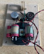
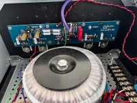
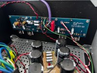
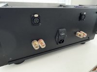
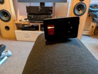
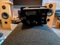
Hi friends, a while back I built this amp for a friend(with some changes). He's been using it for several years without any issues. A few weeks ago, he told me he was hearing a noise on the right channel. I thought it was the 6v6s running out. I set up the oscilloscope and detected a noise/oscillation in the negative part of the sine wave that I can't detect. Can you give me any clues on how to locate the fault? Could it be the OPT? I've already tried another 12ax7 and re-soldered it.
The red marks are where I placed the oscilloscope and found the noise.
The other triode of the 12ax7 and the other 6v6 work ok, to eliminate the potentiometer.
I inverted the 6v6 too.
thanx a lot guys!!
https://diyaudioprojects.com/Schematics/DIY-Push-Pull-PP-6V6-Tube-Amplifier/

The red marks are where I placed the oscilloscope and found the noise.
The other triode of the 12ax7 and the other 6v6 work ok, to eliminate the potentiometer.
I inverted the 6v6 too.
thanx a lot guys!!
https://diyaudioprojects.com/Schematics/DIY-Push-Pull-PP-6V6-Tube-Amplifier/
F3 Clone Board Set Group Buy
- By csample
- Group Buys
- 187 Replies
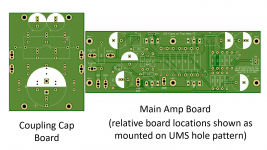
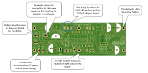
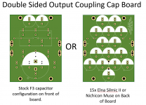
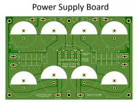
This is a group buy for circuit boards to make a diy clone of the First Watt F3 amplifier. This board set is designed to work with the diyAudio store UMS mounting pattern making life a little easier for those having UMS chassis.
The design is about 80% done and now it is time to gather input and make refinements before ordering a test set of boards to validate the layout.
The images below show the basics, and the .pdf has more details about the boards, preliminary pricing, and a tentative schedule for the group buy.
Here is a link to the F3 UMS Pattern Group Buy Sign Up Sheet
I will make every effort to post weekly status updates to share progress.
Attachments
Need some help to repair Crown 400 CSL
- Solid State
- 6 Replies
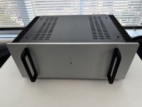
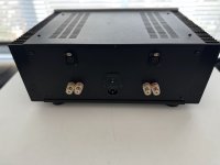
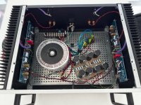
Need some help to repair a bad channel on Crown 400CSL power amp. Need a little help where to look. I seem to have a good signal up to C100 but signal after R101 seems bad. I made a couple videos:
Output off speaker terminals.
Signals at C100 input and R201 output.
Here is schematic: https://schematicsforfree.com/files/Audio/Products/Consumer/C/Crown CSL 460.pdf
Any suggestions appreciated.
Output off speaker terminals.
Signals at C100 input and R201 output.
Here is schematic: https://schematicsforfree.com/files/Audio/Products/Consumer/C/Crown CSL 460.pdf
Any suggestions appreciated.
For Sale Wood enclosure
- By madisonears
- Swap Meet
- 3 Replies
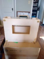
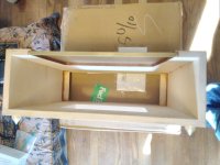
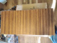
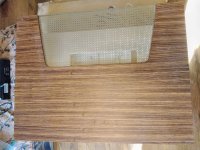
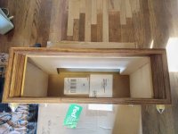
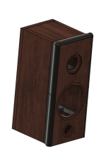
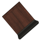
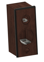
A new wood enclosure in perfect condition, very solidly made of high quality plywood (no voids) with beautiful veneer, brass screen on top, vent opening on bottom, four pointed brass feet.
Overall outside dimensions 21" wide x 16" deep x 7-1/4" high, not including feet, 8-1/4" high with feet. Internal dimensions 19.5" x 14-3/4" x 6". Front opening 17" x 5-1/2". Screened top opening 14" x 7". Bottom opening 11" x 6".
$200 plus shipping.
Overall outside dimensions 21" wide x 16" deep x 7-1/4" high, not including feet, 8-1/4" high with feet. Internal dimensions 19.5" x 14-3/4" x 6". Front opening 17" x 5-1/2". Screened top opening 14" x 7". Bottom opening 11" x 6".
$200 plus shipping.
Attachments
DIY Lightweight Compact 2-Way PA Speaker
- By kweaver
- PA Systems
- 94 Replies
So I am a DJ and occasionally do live shows corporate work as well. Our typical event is 300 people or less, mostly indoors but occasionally outdoors. I am looking to really make my load in/out as simple and easy as possible. Dragging VRX subs and SRX tops in and out of venues by myself is doable but I am getting older now and it seems like it just gets a bit more painful every year.
I would like to go with a Passive rig that can be run by two QSC GXD8 amplifiers or something similar. Keep the processing in the amps and have a simple 5U case at 35lbs. For subs, I have built two of single 15 enclosures using Beyma 15LEX1600nd. The enclosures are complete minus the handles. Waiting for the drivers to come in so I can get the COG right. They should weigh in at right about 55-60 lbs and are very compact. Supposedly they get decently loud. I guess we'll see. If they perform well I intend to build two more for outdoor work.
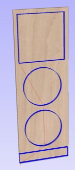
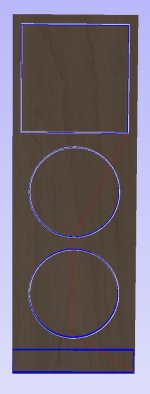
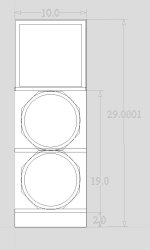
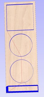
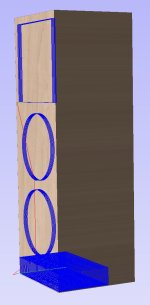
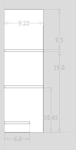
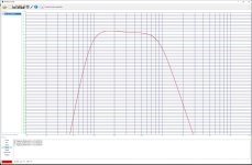
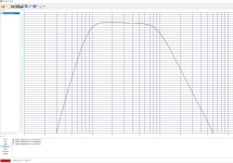
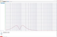
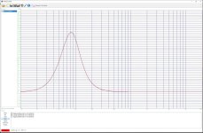
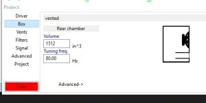
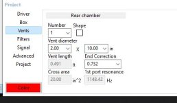
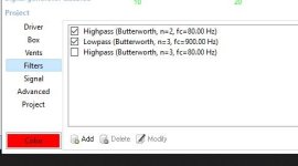
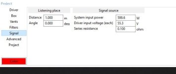
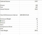
I am struggling a bit with a design for a lightweight 2-way top. But ultimately I would like to us an RCF HF94 coupled with 2 B&C 8MBX51 mid/low drivers. I would like to hp them at 80 to 90 hz and crossover at 900 - 1000. I spent several days in winISD and the attached screenshots are what I came up with so far. In this design I have baffle between the low and high frequency section to keep my volume down. Ultimately, I would like to achieve a true 125db and be under 40lbs.
So besides and suggestions you might have, I have two questions:
1. Is there anything wrong with using a rear port on a PA speaker? I really struggled to find a balance in enclosure volume and port dimensions that were reasonable without exceeding cone excursion parameters. And I could save a few inches in height if I could move the port to the back.
2. Is there a particular compression driver you would recommend pairing with the HF94?
I would like to go with a Passive rig that can be run by two QSC GXD8 amplifiers or something similar. Keep the processing in the amps and have a simple 5U case at 35lbs. For subs, I have built two of single 15 enclosures using Beyma 15LEX1600nd. The enclosures are complete minus the handles. Waiting for the drivers to come in so I can get the COG right. They should weigh in at right about 55-60 lbs and are very compact. Supposedly they get decently loud. I guess we'll see. If they perform well I intend to build two more for outdoor work.
I am struggling a bit with a design for a lightweight 2-way top. But ultimately I would like to us an RCF HF94 coupled with 2 B&C 8MBX51 mid/low drivers. I would like to hp them at 80 to 90 hz and crossover at 900 - 1000. I spent several days in winISD and the attached screenshots are what I came up with so far. In this design I have baffle between the low and high frequency section to keep my volume down. Ultimately, I would like to achieve a true 125db and be under 40lbs.
So besides and suggestions you might have, I have two questions:
1. Is there anything wrong with using a rear port on a PA speaker? I really struggled to find a balance in enclosure volume and port dimensions that were reasonable without exceeding cone excursion parameters. And I could save a few inches in height if I could move the port to the back.
2. Is there a particular compression driver you would recommend pairing with the HF94?
Attachments
-
 Capture 1.JPG57.5 KB · Views: 203
 -
 Capture 2.JPG31.4 KB · Views: 183
 -
 Capture 3.JPG45.6 KB · Views: 155
 -
 Capture 4.JPG55.3 KB · Views: 167
 -
 Capture 5.JPG46.8 KB · Views: 188
 -
 Capture 6.JPG19 KB · Views: 177
 -
 Capture 12.JPG453.1 KB · Views: 177
 -
 Capture 13.JPG408.2 KB · Views: 168
 -
 Capture 14.JPG403.7 KB · Views: 161
 -
 Capture 15.JPG412.2 KB · Views: 147
 -
 Capture 16.JPG15.8 KB · Views: 151
 -
 Capture 17.JPG15.7 KB · Views: 143
 -
 Capture 18.JPG19.5 KB · Views: 132
 -
 Capture 19.JPG20.4 KB · Views: 129
 -
 Capture 20.JPG24.1 KB · Views: 168
Goodmans Magnum K (and K2) crossover diagram needed
Here they are, both K and K2 diagrams, may the interwebs never be void of them again!


For those who want to remove the Lpads on the Ks, here is an altered diagram:

Thanks to all who have contributed to this thread and a special thanks to @chrisng for his tracing and diagram skills! 🙂
--------- Original Post Below ----------
Hi,
I am after the crossover diagram for the Goodmans Magnum Ks.
In this post here: https://www.diyaudio.com/community/...sovers-and-potentiometers.112926/post-1971834 user alspe had previously uploaded the crossover diagram to google drive. It was some time ago though and the link is now dead. It’s not listed in the way back machine either.
I was hoping to contact alspe, but it looks like they are no longer a member here and I can’t tag them.
I have attempted to trace it, but these old xovers are a mess and I’m finding it difficult.
I thought it would be similar to the K2 but it’s not. Not only because of the Lpads, but the filters are different too.
Anyone got it or able to help?
For those who want to remove the Lpads on the Ks, here is an altered diagram:
Thanks to all who have contributed to this thread and a special thanks to @chrisng for his tracing and diagram skills! 🙂
--------- Original Post Below ----------
Hi,
I am after the crossover diagram for the Goodmans Magnum Ks.
In this post here: https://www.diyaudio.com/community/...sovers-and-potentiometers.112926/post-1971834 user alspe had previously uploaded the crossover diagram to google drive. It was some time ago though and the link is now dead. It’s not listed in the way back machine either.
I was hoping to contact alspe, but it looks like they are no longer a member here and I can’t tag them.
I have attempted to trace it, but these old xovers are a mess and I’m finding it difficult.
I thought it would be similar to the K2 but it’s not. Not only because of the Lpads, but the filters are different too.
Anyone got it or able to help?
Attachments

reusing subwoofers in a better enclosure
- By robinlawrie
- Subwoofers
- 19 Replies
Hi All, been offline for quite a while, since i finished my major build. Despite it being a year long learning experience and trying to use best-practise on every aspect (within the limits of my requirements for a compact system) honestly ive never been totally happy with the sound. the subwoofers particularly have never really satisfied me, and the whole system seems to be missing something. The subwoofers (compact things with slot ports) do crank out bass, but its a bit resonant and boomy, and overall the system is missing "slam!"
i remember at the time, i had a laugh when somebody here described my chosen subwoofer drivers (https://www.daytonaudio.com/product/120/rss265ho-4-10-reference-ho-subwoofer-4-ohm) as "mud-shovels" and i assume the criticism was spot-on. i chose them since a) i got them for an amazing price and b) they allowed me to build the subs small (also they did have great reviews so im not a complete idiot)
so anyway, im evaluating options. specifically, im wondering if some other enclosure type might allow these sub drivers to sound better.. ideally also reaching higher to improve the punchiness of the sound. (they claim to go up to 600 hertz, id be happy with kick drum range at 2-300hz.) at the moment they cross over to my dual driver alpair fullrange cabinets (also ported enclosures) at around 85 hz.
Id not go higher with the current cabinets as first, they are not positioned well for stereo imaging if they go higher, second, the drivers are down-firing and third, with a 210 gram cone, they have a habit of jumping off the floor despite weighing close to 20kg.
i was playing with the idea of some kind of transmission line (pvc pipe?) or tapped horns, placed under or behind the fullranges, with the drivers forward firing.
i do vaguely remember however that these drivers were not well suited for tapped horns.
itll break my heart to replace the very pretty (imho) translam cabinets i spent months designing and building, probably with something 3x bigger and ugly. but if it doesnt sound good, whats the point?
any suggestions most appreciated.
For Sale Aleph J in Deluxe 4U Chassis
- By calipilot227
- Swap Meet
- 1 Replies
Hate to see it go, but it's been gathering dust in the closet since I switched to an active monitor setup. I built this amp in 2016 and it sounds great. It has XLR inputs, but can easily be converted to RCA. It is quiet even with sensitive speakers.
Asking $500 obo. Local pickup preferred, but willing to ship within ConUS. I am located in San Francisco. Sold
Attachments
Dual Skar12 paraflex C CRAM
- By maxolini
- Subwoofers
- 294 Replies
Plan on post #83
latest sim and hr file on post#121
###########################
On my quest for a PA sub design that will let me reach 140dB SPL with 4 cabinets and do not use the 700+ Drivers from Beyma, 18sound and B&C that are staples
in high output PA cabinets
i looked for modest options and found a car driver that fits the criteria
since my hornresp skills are very modest, i can not simulate from scratch but punch in different drivers in to existing designs.
i think i found a winner combination.
i will take 2 sheets of ply and 2 skar drivers
143 a piece per driver is 286usd for 3kw power per cabinet
the original design costed about 325 bux in 2013, i calculate that this will cost about 400 to 450
wood plus , handles, casters, paint.
do you guys remember this LAB12 based design ?
https://www.diyaudio.com/community/threads/325-lab-12-based-pa-tapped-horn-35hz-extension.232219/

BP1 was very kind to help and do some mods to the original design that can only house a LAB12
he made S1-S2 baffle length longer so to accommodate 2 skar 12" drivers inline
using 4 cabinets with 2 skar 12 DDX drivers @1.5kW per driver (3kw per cab) we get this


with HP and LP applied we get this

what you guys think?
tweaks ,mods, and improvements are welcome
Max.
latest sim and hr file on post#121
###########################
On my quest for a PA sub design that will let me reach 140dB SPL with 4 cabinets and do not use the 700+ Drivers from Beyma, 18sound and B&C that are staples
in high output PA cabinets
i looked for modest options and found a car driver that fits the criteria
since my hornresp skills are very modest, i can not simulate from scratch but punch in different drivers in to existing designs.
i think i found a winner combination.
i will take 2 sheets of ply and 2 skar drivers
143 a piece per driver is 286usd for 3kw power per cabinet
the original design costed about 325 bux in 2013, i calculate that this will cost about 400 to 450
wood plus , handles, casters, paint.
do you guys remember this LAB12 based design ?
https://www.diyaudio.com/community/threads/325-lab-12-based-pa-tapped-horn-35hz-extension.232219/
BP1 was very kind to help and do some mods to the original design that can only house a LAB12
he made S1-S2 baffle length longer so to accommodate 2 skar 12" drivers inline
using 4 cabinets with 2 skar 12 DDX drivers @1.5kW per driver (3kw per cab) we get this
with HP and LP applied we get this
what you guys think?
tweaks ,mods, and improvements are welcome
Max.
Edge Diffraction Testing - Shapes
To spice up my boring 2 way build I am going to try some 3d printed edge diffraction pieces to see what difference they might make.
I will be starting with this aerofoil/teardrop shape. This is a pretty small one but I can make it wayyyyy bigger which is probably what I will try next.
Does anyone else have a shape they would like me to test? Let me know. Let's do some science!
I will be starting with this aerofoil/teardrop shape. This is a pretty small one but I can make it wayyyyy bigger which is probably what I will try next.
Does anyone else have a shape they would like me to test? Let me know. Let's do some science!
Attachments
Type of Resistor Material Choice
- By ewalkrambo
- Electronic Design
- 6 Replies
Hi folks, I've noticed a lot of misinformation about people using ferrite (Fe2O3, or commonly referred to as rust) resistors in audio electronics and other electronics. It's actually a horrible choice of material for a resistor. Ferrite is used in antennas! If you want to get hacked offline or to pick up interference from random crap, ferrite is a great choice of material in your resistors.
I think a lot of you are making your own electronics specifically to avoid talentless hacks screwing everything up. If that is the case, you are perhaps better off with some sort of ceramic material for resistors, just make sure your power rating has sufficient watt throughput capability.
The benefit to using ferrite is that the resistors are very small. If you are shielding everything or are not worried about talentless hacks ruining your fun, ferrite is a great choice. Otherwise, choose resistors made out of a different material -- especially if you are in aerospace.
Help with VPI SDS
- By klooker
- Analogue Source
- 3 Replies
I just got a VPI SDS but I don't think it's operating correctly.
I connected it to my VPI TNT Jr and it worked but pressing the rpm button woudn't do anything nor would the up/down arrows. I messed around with it and was able to change speed by simultaneously pressing rpm & down arrow. I could change the frequency by pressing rpm & up arrow. This would lower the frequency but I can't figure out a way to raise it. I also can't get into setup. The output voltage & frequency match the display.
I assume this is a firmware issue?
Thanks.
Kevin Looker
LM3886: LTSpice XVII Errors
- By RonLat
- Software Tools
- 9 Replies
I‘m trying to simulate the LM3886 with the LM3886.lib from Texas Instruments in LTspice XVII. The schematics is from the datasheet. When I run the simulation, the error log is telling me:
I assume that something is not connected properly but I can‘t figure out what it is?
I renamed the LM3886.asy to LM3886.asy.txt and the LM3886.lib to LM3886.lib.txt, so they can be uploaded with this post.
The Texas Instruments Support can't help with LTspice XVII, because they support only TINA-TI or PSpice.
Code:
ERROR: Node U1:11 is floating and connected to current source G:U1:U2:R1
ERROR: Node U1:U_TF:VP1 is floating and connected to current source G:U1:U_TF:P1
ERROR: Node U1:U_TF:VP2 is floating and connected to current source G:U1:U_TF:P2
ERROR: Node U1:U_TF:VP3 is floating and connected to current source G:U1:U_TF:P3
ERROR: Node U1:U_TF:VP4 is floating and connected to current source G:U1:U_TF:P4
ERROR: Node U1:U_TF:VZ1 is floating and connected to current source G:U1:U_TF:Z1
ERROR: Node U1:U_TF:VZ2 is floating and connected to current source G:U1:U_TF:Z2
ERROR: Node U1:U_TF:VZ3 is floating and connected to current source G:U1:U_TF:Z3
ERROR: Node U1:U_TF:VZ4 is floating and connected to current source G:U1:U_TF:Z4
ERROR: Node U1:17 is floating and connected to current source G:U1:U_TF:Z5
I assume that something is not connected properly but I can‘t figure out what it is?
I renamed the LM3886.asy to LM3886.asy.txt and the LM3886.lib to LM3886.lib.txt, so they can be uploaded with this post.
The Texas Instruments Support can't help with LTspice XVII, because they support only TINA-TI or PSpice.
Attachments
Taramps Smart 5 Bass
- By Deadly Sones
- Car Audio
- 18 Replies
Good day,
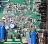
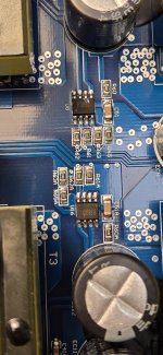
Anyone happen to know what diode was in place at location D6? It was completely melted out of the amp when I got it. The MJD32C burned the pad up pretty good.
Thanks in advance!
Anyone happen to know what diode was in place at location D6? It was completely melted out of the amp when I got it. The MJD32C burned the pad up pretty good.
Thanks in advance!
Attachments

Looking for drivers with max dispersion
I have a strange setup I'm looking to update. I do the bulk of my music listening in my kitchen and the only place to put speakers to get decent soundstage around the whole room is on the ceiling. So I stumbled on DML speakers and made some 2x2' panels from styrofoam. With some heavy DSP and a sub they sound great honestly.
However I am just kind of bored and looking for a change so I want to keep the same ceiling hung config but build new speakers that address the shortcomings of the DML panels. The shortcomings are basically general inefficiency, high LF rolloff (about 200-250Hz from what I remember) and the heavy handed DSP to flatten the response. The great thing about them is the imaging- there is basically no beaming, at least to my ears, which is great considering how much I move around the kitchen.
So I am looking to make new 2x2' panel speakers with conventional drivers that have minimal beaming/max dispersion all the way up the frequency range. My gut says to just pair an in ceiling speaker with a high QTS 10-12" driver and call it a day. But I'm also open to running a WMT 3 way setup as well. Imaging doesn't have to be perfect.... I just don't want any high frequency hot spots in the room. What do you recommend?
Logic TX3000D Rail caps keep blowing out
Great day guys, this amp keeps blowing out the rail caps mainly the negative side, what could be the issue why it’s doing that, power on ok, then even with low volume it’s just pops the caps, I’ve change them but there seems to be an issue otherwise.


For Sale Raw Wire and connections
- By Jeffrey 01
- Swap Meet
- 6 Replies
Good Morning. Here’s my Second post to clean out some stuff I don't need.
1. I have a lot of Gotham Audio wires and connections I bought from swisher land and shipped to my house. Never used.
2. I have a few Belden speaker wires and so on for sale. Never used.
3. I have some Canare Wires all speaker wires and the 4S11 (O.F.C.) I paid more for per. Foot and the regular 4S11 cables. Never used.
4. I have some whirl wind speaker wires and cbi Speaker wire and West penn wire as well. I have Redco’s only House brand speaker wire too. I have very little Dayton Audio wire but, I have some.
I have some Binding post from Dayton Audio and Gotham Cables and RCA plugs as well.
I have quick connections Gold and silver ones for speaker cable and driver hook ups.
I can take pictures and send them to anyone who wants to see pictures of the products.
I would love to sell local it would be a lot of little things to ship out. I also Have the wire in a sealed container.
E mail me with Questions about things for sale. I can be reached at Jmboo1922@gmail.com. Thanks Jeff
Hello from Finland
- By tompp4
- Introductions
- 2 Replies
I’m recently new to the hifi hobby and have always been intrigued by building things yourself. I’ve studied electronics and embedded systems in schools even though IT was always my major. Now I’m looking to re-ignite my interest in electronics via hifi. 🤓
right compression driver and horn for complicated system
Hello.
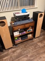
I have two couple of speakers with altec lansing 409-8c coaxial drivers, each of them driven by an integrated tube amp. One couple of these altec goes first through the speaker level imputs of two vintage Yamaha subwoofers. A couple of pictures, so you will understand:


These Altec speakers have a sensitivity of 97 db, nominal impedance 8 ohm and minimum impedance 6 ohm, and an advertised frequency response of 50 hz/14 khz.
I would like these speakers to be driven in parallel by just one amplifier, each channel going first through one active subwoofer, then two coaxials in parallel and, in order to have a higher impedance as a result, I would like to add a 16 ohm vintage compression driver and horn for each channel, with a crossover like EV c35.
Do you think it will work? What kind of impedance will I have? What vintage compression driver and horn do you recommend? What crossover?
(I can't build a crossover myself, I'm quite a novice)
What kind of sensitivity will I have with two 97db speakers in parallel for each channel? 100 db?
In short, each channel, after the amplifier, there will be a subwoofer, two coaxial drivers Altec 409 in parallel, then a crossover and a compression driver and horn. The horn will go on top of two speakers.
In short, if this is feasible, what I lack is compression drivers, horns and crossovers, and also the knowledge. Compression drivers and horns should not be very heavy. I've got fibromyalgia and can't lift heavy weights.
Thanks in advance.
I have two couple of speakers with altec lansing 409-8c coaxial drivers, each of them driven by an integrated tube amp. One couple of these altec goes first through the speaker level imputs of two vintage Yamaha subwoofers. A couple of pictures, so you will understand:
These Altec speakers have a sensitivity of 97 db, nominal impedance 8 ohm and minimum impedance 6 ohm, and an advertised frequency response of 50 hz/14 khz.
I would like these speakers to be driven in parallel by just one amplifier, each channel going first through one active subwoofer, then two coaxials in parallel and, in order to have a higher impedance as a result, I would like to add a 16 ohm vintage compression driver and horn for each channel, with a crossover like EV c35.
Do you think it will work? What kind of impedance will I have? What vintage compression driver and horn do you recommend? What crossover?
(I can't build a crossover myself, I'm quite a novice)
What kind of sensitivity will I have with two 97db speakers in parallel for each channel? 100 db?
In short, each channel, after the amplifier, there will be a subwoofer, two coaxial drivers Altec 409 in parallel, then a crossover and a compression driver and horn. The horn will go on top of two speakers.
In short, if this is feasible, what I lack is compression drivers, horns and crossovers, and also the knowledge. Compression drivers and horns should not be very heavy. I've got fibromyalgia and can't lift heavy weights.
Thanks in advance.
Diy Lampucera DAC arrived
- Digital Line Level
- 11 Replies
Hello Everyone how are you all 🙂. My diy Lampucera has arrived. It has not come with any instructions. It has two power supply transformers I don't know where the one with yellow wires connects. As I look at everything to do with the dac it's starting to become clearer what to do and one of the things is ask a friend of mine who solders better than me to help me. To test it to see if it works do I need a metal case first and is everything I need to get it working in this kit I know I need a power cable to connect it to the on off power connector that comes with it.
https://www.ebay.co.uk/itm/18672783...46UT_E9QjS&var=&widget_ver=artemis&media=COPY
https://www.ebay.co.uk/itm/18672783...46UT_E9QjS&var=&widget_ver=artemis&media=COPY
Attachments

HELLO ALL...Need help with circuit Schematic for Arcam DAC
- By Azan
- Introductions
- 2 Replies
Hi All,
Im a hifi enthusiast from Malaysia with limited DIY experience. I picked up hifi during my university time in the mid 90s in the UK. It seems the bug is still with me until now. I run 2 sets of stereo separates, one with ole chrome and the other with olive naim amplifiers at the heart, sources are Arcams and Audiolabs and speakers are Epos and Mission.
3 days ago, my trusty 30 year old Arcam Black Box 50 stopped working. One thing I notice is that the sync lock light is stuck ON all the time (cannot be switched off) and there's no red light at the sync lock terminal at the back of the unit. My go-to CD player repairman asked if I can get a hold of the correct circuit schematics. He's got the repair manuals, but its not sufficient it seems.
I was wondering if anyone here can assist me on this issue, or even help with the circuit schematics of the Arcam Black Box 50. I can be contacted via WhatsApp at +60123827078. Thanking all in advance and looking forward to making your acquaintances and sharing of ideas here.
the DFE Loudspeaker Crossover Family - steep "analog" style crossovers with controlled group delay
- By CharlieLaub
- Multi-Way
- 6 Replies
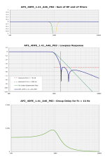
I recently published an article in audioXpress (September 2024) about a new family of loudspeaker crossovers that I call "DFE Crossovers". The filters that make up these crossovers are derived from elliptic filters (giving rise to the DFE name) are characterized by:
The DFE family consists of over 30 examples, having order from 3 to 8. Variations such as "squared" crossovers (like the Linkwitz-Riley crossover) and combinations of all-pole and DFE crossovers (AP-DFE), are included in the "family". The AP-DFE type can be implemented as a mixed passive+active hybrid, with the all-pole part implemented as a passive crossover and the DFE part using analog active or IIR DSP means. This has the advantage of suppressing harmonic distortion within the LP filter passband (see this Purifi tech note for more information).
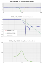
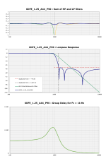
The audioXpress article provides full details on the DFE crossovers, but I will provide a couple of examples below. I typically present the lowpass filter response, a zoomed-in view of the LP+HP sum, and the group delay of the crossover. The highpass filters is simply the lowpass mirrored about the crossover frequency. Please see the following attachments:
The elliptic-like response of these crossovers is well suited to loudspeaker crossovers because stopband attenuation of more than about 50dB is not necessary. Instead it is better is to quickly transition between passband and stopband (e.g. the transition band is narrow). Most non-FIR filters with such narrow transition bands would produce excessively high group delay that would cause audible phase distortion, but I have used the extra degrees of freedom to design the DFE Family filters to have sufficiently low group delay as to not give rise to audible distortion in the time domain signal.
Overall these filters offer an interesting mix of capabilties that has not yet been available except through FIR filtering. The DFE filters can be implemented with analog active circuits or IIR DSP, and remain easy to use and relatively lightweight. You can download information about the complete DFE Crossover family at the following link:
https://audioxpress.com/files/attachment/2777
.
- steep transition bands, up to ~150dB/octave
- a stopband that is finite in depth, typically 40dB-50dB but sometimes more
- excellent LP+HP summation with very low ripple
- low group delay (below the threshold of audibility reported in the literature)
The DFE family consists of over 30 examples, having order from 3 to 8. Variations such as "squared" crossovers (like the Linkwitz-Riley crossover) and combinations of all-pole and DFE crossovers (AP-DFE), are included in the "family". The AP-DFE type can be implemented as a mixed passive+active hybrid, with the all-pole part implemented as a passive crossover and the DFE part using analog active or IIR DSP means. This has the advantage of suppressing harmonic distortion within the LP filter passband (see this Purifi tech note for more information).
The audioXpress article provides full details on the DFE crossovers, but I will provide a couple of examples below. I typically present the lowpass filter response, a zoomed-in view of the LP+HP sum, and the group delay of the crossover. The highpass filters is simply the lowpass mirrored about the crossover frequency. Please see the following attachments:
Example 1: 5DFE_1.50_A48_P0
Example 2: 6DFE_1.25_A44_P90
Example 3: AP3_4DFE_1.41_A46_P83
The elliptic-like response of these crossovers is well suited to loudspeaker crossovers because stopband attenuation of more than about 50dB is not necessary. Instead it is better is to quickly transition between passband and stopband (e.g. the transition band is narrow). Most non-FIR filters with such narrow transition bands would produce excessively high group delay that would cause audible phase distortion, but I have used the extra degrees of freedom to design the DFE Family filters to have sufficiently low group delay as to not give rise to audible distortion in the time domain signal.
Overall these filters offer an interesting mix of capabilties that has not yet been available except through FIR filtering. The DFE filters can be implemented with analog active circuits or IIR DSP, and remain easy to use and relatively lightweight. You can download information about the complete DFE Crossover family at the following link:
https://audioxpress.com/files/attachment/2777
.
Attachments
Dynakit Z565
- By electricgas
- Tubes / Valves
- 0 Replies
Would anyone have a Dynakit z565 output transformer, either a new or a used one in good electrical condition that you would be willing to sell?
Generic 8k full bridge
- By Deadly Sones
- Car Audio
- 17 Replies
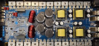
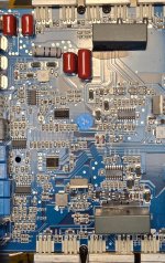
Forgive me while I learn these full bridge amps.
This amp powers on, makes rail voltage but has clip light on.
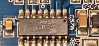
Output doesn't seem to be switching. I believe if I lift Diodes 10/11 that will force the MIC8280 (U7) to send pulses? The driver ICs are CSC3127's? Can't find much of anything on them. They then seem to feed 2 pair of 1797/4672 buffers.
What's the best plan of approach here?
Outputs don't seem to be shorted.
One 1 set of outputs I have G(55v) D(124v) S(55v)
Other set of outputs I have G(0V) D(55v) S(0v)
Same on both sides of the amp.
This amp powers on, makes rail voltage but has clip light on.
Output doesn't seem to be switching. I believe if I lift Diodes 10/11 that will force the MIC8280 (U7) to send pulses? The driver ICs are CSC3127's? Can't find much of anything on them. They then seem to feed 2 pair of 1797/4672 buffers.
What's the best plan of approach here?
Outputs don't seem to be shorted.
One 1 set of outputs I have G(55v) D(124v) S(55v)
Other set of outputs I have G(0V) D(55v) S(0v)
Same on both sides of the amp.
Attachments
Parts/transformer for SOB/Rozenblit OTL
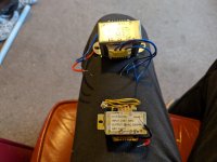
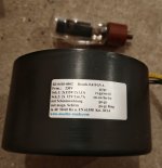
I bought this massive transformer several years ago and never realised this project. It is the 15 watt OTL with EL509 Tubes.
It is made by a very well regarded German company, it also has a magnetic shield.
Some parts come with it, see Photo.
I also can add eight 6s45p tubes for 70€, they should work fine.
Preferably shipping to Europe, as it is pretty heavy which will drive shipping cost up.
Price 200 Euro for the whole package including tubes, 130 without.
Attachments
For Sale Test Equipment and books and CDs. Cheap.
- By Jeffrey 01
- Swap Meet
- 0 Replies
(update) Wellers solding station not sold. Thanks everyone. Good Afternoon. I have the Following Items for sale. Fell feel to make me in offer even after I put what am asking for? I can also send pictures. Here is my
E mail. Jmboo1922@gmail.com
Items for sale.
Sold1.Bass box and Crossover pro programs with books cd and both product numbers. Asking $50.00 and You pay shipping. Books in excellent condition.
Sold/2.Dayton Dats v3 mint condition comes with everything and even the original box. I also thrown in the mass scale new and the Probe that slows down your speaker and so on and the original woofer test 2 from Smith and Larson with everything it comes with and even the box. and The winspeakerz and the subwoofer tool box program. Am asking $120.00. You pay for shipping. (If you do local pick up I will Give away a tripod and a 4x8 piece of acoustic foam to put around the tripod).
(Not sold yet)A. I have a digital Weller a soldering station with a soldering smoke fan. I’m asking $100.00. Brand new never used any of them. I have paper work on both. You pay for shipping.
I will only ship to the 48 United States. Thanks Jeff
Vance Dickason and Distortion Measurement - WHY?
- Full Range
- 26 Replies
2" Peerless by Tymphany - nice driver, right ?
https://audioxpress.com/article/test-bench-peerless-by-tymphany-full-range-2-pls-50n25al01-08
wait what is this ?

20% THD ? how ???
well ...
"For the distortion measurement, I mounted the Peerless by Tymphany 2” rigidly in free air"
he always does that ... FREE AIR ... WHY ??? he had it mounted in an enclosure for his other tests:
"I mounted the PLS-50N full-range in an enclosure, which had a 9” × 4” baffle and was filled with damping material (foam)."
but for distortion measurement it is now in free air ... "rigidly mounted" ... he says it like it's some kind of an achievement ... as if mounting it flexibly would produce a different result ...
that makes no sense ... of course without enclosure the low frequency of fundamental will get cancelled out by the back wave while the higher frequency of harmonics will not, causing the measured ratio of harmonic to fundamental to shoot way up to something absurd like 20% THD ...
does anybody actually believe that a driver from a major manufacturer would have 20% THD in the middle of the passband when measured correctly ?
why does he keep doing this ? isn't he the guy who wrote the loudspeaker design cookbook ? surely he knows better ?
what is going on ?
https://audioxpress.com/article/test-bench-peerless-by-tymphany-full-range-2-pls-50n25al01-08
wait what is this ?
20% THD ? how ???
well ...
"For the distortion measurement, I mounted the Peerless by Tymphany 2” rigidly in free air"
he always does that ... FREE AIR ... WHY ??? he had it mounted in an enclosure for his other tests:
"I mounted the PLS-50N full-range in an enclosure, which had a 9” × 4” baffle and was filled with damping material (foam)."
but for distortion measurement it is now in free air ... "rigidly mounted" ... he says it like it's some kind of an achievement ... as if mounting it flexibly would produce a different result ...
that makes no sense ... of course without enclosure the low frequency of fundamental will get cancelled out by the back wave while the higher frequency of harmonics will not, causing the measured ratio of harmonic to fundamental to shoot way up to something absurd like 20% THD ...
does anybody actually believe that a driver from a major manufacturer would have 20% THD in the middle of the passband when measured correctly ?
why does he keep doing this ? isn't he the guy who wrote the loudspeaker design cookbook ? surely he knows better ?
what is going on ?
Omicron, a compact headphone amp with -140dB distortion
- By alexcp
- Headphone Systems
- 559 Replies


Omicron is:
- A compact, ultra-low distortion headphone amplifier that we developed jointly with @Rus2000 from the RCL-electro.ru forum
- Designed to work with 32 to 600 ohm headphones and tested with a range of over-the-ear and on-the-ear cans from AKG, Beyerdynamic, Grado, Klipsch, and Sennheiser but proved to be equally at ease with lower impedance headphones, such as 8-ohm AKG's K3003 3-way in-ear monitors and 18-ohm HIFIMAN's planar magnetic HE5XX; the ubiquitous white Apple EarPods (tethered ones, both 1st and 2nd generation) sound great with Omicron, too!
- Very musical, with pure, clean, liquid sound and perfect clarity even in the most harmonically complex pieces. Those who built the Omicron often report that its sound is addictive, and that it is hard to put the headphones down when listening to music.
The sound immediately fascinated me so much that I began listening without adjusting the quiescent current. You want to turn up the volume, no mess, even the quietest sounds are clearly heard, but at the same time the sound is very comfortable, not harsh, a beautiful three-dimensional scene. Very nice bass. In short, top notch!
... sounds flawless and works equally well. [...] The claimed <140db probably holds true because this design sounds cleaner and smoother than anything ive built and that includes single opamp setups and well known discretes.
This amp is fantastic, I've been listening away and taking notes for a better review, spent a few hours last night playing games with it, worked wonderfully. It really blows all of my other headphone amps and line amps out of the water. The clarity is surreal.
Last night compared Omicron with my composite LT1210 based headamp. At first, it seemed that the LT1210 sounds softer and more beautiful, but after listening to Omicron for about an hour, I switched back and realized that now I want an Omicron for myself! With the same tonal balance, it gives an accurate, fast, assertive bass and better conveys space. Sounds great on good recordings.
...the sound really is fantastic. [...] It's a huge step up from [...] bottlehead crack with the speedball upgrade.
The soundstage is really amazing with my hifiman cans and there's a wonderful amount of detail. Very liquid sounding and the amp just seems to do everything right. The amp runs very cold too, the case never even gets warm.
The Omicron is a fantastic headphone amp and preamp, the background is more black and bass is more deeper and punchier. Also the clarity is absolutely amazing, the vocal is no doubt much clear from the track "Mistakes from Lake Street Dive" than before.
And the crossfeed did something, especially from older track or some track that the musical instrument sounds are more biased toward the left and right channels. Toggle on the crossfeed makes the soundstage a bit wider and the sound is no more at the front but a bit lay back, more natural.
I have the feeling my old Beyerdynamic DT-880S from 1984 in combination with the Omicron never sounded that good.
Sounds good! [It has] no sound of its own. The resolution is there, and so is the bass. Highs and mids are very clean. I have been using it for a month, will put it in a case now.
This little amp is something else. Listening last night it really started to open up after a couple of hours. Bass goes deeper than any of my other headamps. Very black background. Smooth yet detailed. I ended up listening much later than I had planned. Very musical. Definitely a keeper.
Features:Easy to build and excellent.
- Vanishingly low distortion: with THD and IMD better than -140dB (0.000 01% - that's only 100 parts-per-billion), Omicron is orders of magnitude more linear than other "high-performance" and "ultra-high performance" amplifiers
- Compact: Just one IC and two transistors per channel
- Inexpensive, commonly available parts (NE5532, BD139, BD140; under $40 at Mouser for the whole BOM)
- Easy through-hole construction (NEW: a smaller board with easy-to-hand-solder SMT parts has been developed, see its photo above)
- Functionally complete: One 80×110mm (60×90mm for the SMT version) board carries two amplifier channels, a sensitive DC protection for your headphones and an optional (switchable in the SMT version) cross-feed circuit, which helps create a realistic soundstage in headphones
IMD 19+20kHz, 5Vpp @32ohm (see post #11 for more measurements):
Theory of operation:
- Schematic design: post #2
- Mod: increasing input impedance: post #67 (this mod is now the stock version and part of the BOMs linked below)
- Loop gain (simulated): post #27
- Crossfeed schematic and frequency response: post #33
- DC protection: post #34
- Power supply: post #35
- Distortion, clip, frequency response: post #11
- Distortion and clip for the SMT version with no heatsinks and half the quiescent current: post #109
- Through hole Omicron board
- Schematic: post #295
- Board outline: post #142 - includes a discussion of how to fit Omicron into 1U enclosure
- Part list: post #155
- Winding the output inductor: post #71
- Mod: crossfeed switch board by @gajira: post #334
- Mouser shared project - order all parts for this board in one click
- SMT Omicron board
- Schematic: post #297
- Board outline: post #299
- Part list: post #298
- Mouser shared project - order all parts for this board in one click
- Power supply board
- Schematic and board outline: post #300
- Part list: post #301
- Mouser shared project - order all parts (except the power transformer, see post #174 for what's recommended) for this board in one click
- Assembly guide: post #225
- Choosing volume control: post #170
- Mod: running Omicron from +/-12V rails
- Opamp substitution: one, two.
- Post #173 - yours truly
- Post #226 - @bloqhed
- Post #287 - @ElArte - Fallout themed!
- Post #311 - @ElArte, another build
- Post #330 - @Will2226
- Post #393 - @Mulburg - in a vintage toaster!
- Post #402 - @emuffler
- Post #425 - @Mulburg, a more conservative build
- Post #479 - @jwchen119
- Post #545 - @namghiwook
Hiya!
- Introductions
- 1 Replies
Hiya, I'm joining this site in an attempt to learn how to fully fix my beloved NAD 7240PE and also just absorb more knowledge on audio amps in general 🙂
Hello
- By BlakeJones
- Introductions
- 1 Replies
I am new to this site. From Australia. I have signed up to talk with audio professionals about live PA systems. I have built a 20hz tuned tapped horn, and a FLH line array kick bin for drum and bass/ house rave parties. I currently have an event startup for rave parties within my state. I am also a software engineer and have some ideas I'll be developing over the next few years. Id love to chat with individuals and share ideas I have.
Attachments
New Member
- By aurum
- Introductions
- 1 Replies
Hi All,
Im a hifi enthusiast from China with limited DIY experience.
Im a hifi enthusiast from China with limited DIY experience.
My name's Ryan
- By Rshep08102
- Introductions
- 1 Replies
I’m from Montana and I’m here because I have a unique Rockford fosgate amp that nobody locally appreciates and so I’ve been having issues selling it for even half what it goes for. It’s a vintage t1000bd from what I can tell it’s a 25 to life edition and it works with no issues. Any help pointing me in the right direction would be neat oh and I’m looking to get somewhere between 3-500 out of it.
Tinysine TSA (8804) gain structure
- By swann
- Digital Line Level
- 0 Replies
Hello,
i am embarked on my first DSP/Amp trial and ran into some issues regarding the gain structure with this board. While programming and measuring it with REW i got the board very easily into clipping (REW output measured at 1.5 Volts Output) without getting even full power on the outputs of the board (was not trying to anyway). So my question in general is, does someone have/had experience with tinysine boards and is able to tell, how to approach this whole topping of using an analog input without getting it into clipping/distortion whilst getting maximum output possible?
There are some dip switches on the board which i did not even touch and i am running it with a propper 36 Volts power supply.
Would be glad to getting pointed into some directions how to avoid clipping with the analog inputs!
Greets Swany
Musical Fidelity A1 - Problem
- By fencki
- Solid State
- 95 Replies
Hi.
I got the MF-A1 for repair.
Someone had tried to repair the beast before and has done some strange stuff.
I have tried to replace all suspect parts.
One side of output transistors were dead.
So now after replacing and recapping, the amp doesn´t work.
I have about 400mV on the outputs and my output transistors don´t work and are not turned on.
Output transistors are healthy and all other transistors too.
Anybody have an idea?
looks like I am missing something but I can´t figure it out...
Thx.
project: Emperor L26ROY (tweeter + Yamaha JA-0801 + Seas L26ROY)
This is a new thread started from a rando post here: https://www.diyaudio.com/community/threads/headshakes-far-field-3way.382393/post-7434715
I've made a 3" ETON + t25b box before and this will be a reworking of the same setup. I like the idea of being able to swap out the HF/MF boxes.
The Seas L26ROY is in a PartsExpress box. It is by chance that it fits without any adjustment.
I will measure the drivers next and make an ideal sim to reference along the way.
The JA-0801 is in a foam baffle for now. I used some Loctite power grab and some wood skewers to hold the stand together. Metal screws are holding the driver down.

The hypex FA123 can be seen at the bottom of the image.
The tweeter will be picked later.
A translated info sheet about the dome:

I've made a 3" ETON + t25b box before and this will be a reworking of the same setup. I like the idea of being able to swap out the HF/MF boxes.
The Seas L26ROY is in a PartsExpress box. It is by chance that it fits without any adjustment.
I will measure the drivers next and make an ideal sim to reference along the way.
The JA-0801 is in a foam baffle for now. I used some Loctite power grab and some wood skewers to hold the stand together. Metal screws are holding the driver down.
The hypex FA123 can be seen at the bottom of the image.
The tweeter will be picked later.
A translated info sheet about the dome:
raspberry pi
I'm not really trying to transform the 'pi. I just to make it store and play music. I have the RPi 4 with 8gb ram. Is there any downsides to using it as a media player? The major upside for me is space. I'm using a big clunky PC in a ATX mid tower that is hooked up to my JVC Audio/receiver/dac/amp now. I'd really like to clean that area up nice and neat. I'd like to hear some dos/donts from people who are using one. I'm not looking to make chicken salad from chicken s**t but I would like a good sounding system. TIA
Nikko Beta II preamp - Decrease gain
- By manamanam
- Analog Line Level
- 6 Replies
I have a Nikko Beta II preamp (the D-TYPE) that has too much gain for modern sources.
Is there any way to decrease its gain by some 15dB?
Service manual attached.
Any input is appreciated!
Is there any way to decrease its gain by some 15dB?
Service manual attached.
Any input is appreciated!
Attachments
Tube music distorter?
- By drteming
- Tubes / Valves
- 9 Replies
Having just built a LM3886 chip amp and finding it too clean, I'm looking to add some tube warmness. I don't need any gain in a preamp, but a buffer with a cathode follower would probably be too clean. I need a grounded cathode stage. I whipped this up:

It seems to work on the bench, 2V P-P in, 2V P-P out. However, I have a very janky benchtop SMPS, and there's a lot of noise on the scope so I can't really measure anything. Is this thing a good idea, or an abomination? I would think the amount of feedback would squash a lot of the harmonic distortion. Should I go with a voltage divider at the input and AC couple the cathode follower without the feedback? Thanks, all.
It seems to work on the bench, 2V P-P in, 2V P-P out. However, I have a very janky benchtop SMPS, and there's a lot of noise on the scope so I can't really measure anything. Is this thing a good idea, or an abomination? I would think the amount of feedback would squash a lot of the harmonic distortion. Should I go with a voltage divider at the input and AC couple the cathode follower without the feedback? Thanks, all.
For Sale MarkAudio MAOP 11 New, Fostex & more
- By Jeffrey 01
- Swap Meet
- 12 Replies
Good Morning Everyone. I am cleaning out some of my Raw drivers that has never developed into projects I wanted to get done. So I have the following Drivers
for sale.They have never been used and are in a non smoke environment. They have been stored in a controlled environment and it never gets to hot or cold. They are in their original boxes. I will only ship to the 48 United States. I have the following for Drivers for sale. I will be moving into a smaller house Eventually and am going to get rid of everything I don’t use or needed anymore. Spring cleaning.
Mark Audio Drivers.
💥(Updates)1.MAOP 11- Driver’s. Original cost $589.00 a pair. Am asking $400. 00 for the pair . . You pay for shipping.
Sold/ 2.MAOP-5 Driver’s. Original Cost $277.00 a pair. Asking $200.00 you pay for shipping.
2. Puvia Seven HD in the gold color. Original cost $99.40 a pair. Am asking $60.00 a pair you pay shipping
Fostex Full Range driver.
1. FE126E speakers. Am asking a $100.00 A pair. You pay For shipping. New
2.FE126NV speaker. Original cost $140.00 a pair.New Asking $110.00you pay for Shipping.
(Updated)A. Dayton Audios RS125-4 5 inch reference 4 ohm speakers brand new. Cost per. Driver is $44.98. Asking $60.00 and you play for shipping.
Sold/ B. I have a pair of Vifa/ Peerless Ring tweeters the 4 ohm version. Model XT25SC90-04. $21.29 each. Asking 30.00 a pair you pay shipping .(Given away with Fostex speakers).
Sold/ C. I have some paper cone tweeters from Parts Express as a buy out. I think 4 of them at O.68 cents each. (Given away with Fostex Speakers).
I would like to sell for local pick up unless someone is willing to pay for shipping?
For these items listed below.
1. CHN-50P Driver’S. Original cost $40.00 a pair plus shipping was around $14.00. Am asking $25.00 a pair. You pay for shipping.
2.Auible Physics 2” inch speakers. (Newark Company and use to me MCM Electronics). Cost $22.40 each so $44.80 is the total cost plus $15.00 Shipping. So I would like to get $20.00 for the set. You pay shipping.
(Updated price)1. Used Am for sale. Dayton Audios
APA102 BT.Class D amplifier blue tooth. Cost. $184.98 I’m asking $80.00 and I will throw in a nice pair of Studio Master speakers for free. Local Pick up. Speakers
Speaker boxes for sale$
(Updated).A. Frugal Horn XL speaker boxes for sale. I have new Dayton Audio Binding post and Wire for these speakers. Pictures added now. Make me an offer for these boxes.
I can send pictures of speakers you are looking for or interested in. You can e mail me at
Jmboo1922@gmail.com with any questions and offers if you think it’s reasonable? Thanks Jeff
Sold ( Thank You) but, wasn’t in the selling post. Fostex FF166K ENAbled Drivers From planet 10 Hi-Fi.
Sold (Thank you) But, Wasn’t on this selling post. RCA ends. Sold. I have no more left of this item.
Attachments
So what about IMD?
- By njswede
- Solid State
- 8 Replies
There's been a few threads about THD and its pros and cons and they always devolve into philosophical discussions.
So what about IMD (InterModulation Distortion)? I came across an article by Nelson Pass where he argues that it's a much bigger problem than THD and I agree with him, since IMD is a non-musical distortion. As we all know, all musical instrument produce harmonics, so harmonic distortion blends into the music, whereas IMD is going to be "off key".
I did a crude measurement of the IMD using the SMPTE method on my latest build. It came out to about 0.02% on a resistive load and slightly higher on a speaker. I think it was at around 5W. Is that good? Should I be worried? How do you mitigate IMD? Does a high OLG increase the risk of IMD? I know that Pass argues that you should get rid of the feedback altogether, but that opens a whole new can of worms.
I'm here to learn from you smarties. 😀 (And comments like "Don't measure, just listen" aren't useful. I want to understand the theory)
Making a pair of desk speakers from trash
Good evening, I wanted to share my silly project about making two speakers from stuff I had lying around / was gifted to me
All the information relative to this are well written and illustrated on my blog https://www.mimifactory.com/, otherwise this post would've become too long.
A friend gifted me some old car speakers, instead of throwing them away. Plus I got some broken panasonic speakers that I had laying around for a while.
It was quite simple taking the plastic cover away, but then i realized there was no hole for the tweeter and there were two big open slots, that I had to cover if I wanted to make an enclosed loudspeaker.
I drilled a hole with a hole saw but it was too big so I had to 3D print a gasket lol
And make two wood pieces by hand to fill the two big slots.
Capacitor in series with the small speaker = high pass filter kinda
Disconnected central coil from second speaker otherwise I had too many highs
Glued everything, filled with silicone, covered the outer silver parts with some wood grain texture adhesive, and then made a front cover mesh from unused wood and old cloth.
I am currently using them with the subwoofer unit of a LM1875 based 2.1 sound system that had its satellites missing.
I wouldn’t call this Hi-Fi, but it’s pleasant enough to allow me to not always use my headphones and have my hair always messy xD
Great for youtube, videocalls, etc. Basically free as well

All the information relative to this are well written and illustrated on my blog https://www.mimifactory.com/, otherwise this post would've become too long.
A friend gifted me some old car speakers, instead of throwing them away. Plus I got some broken panasonic speakers that I had laying around for a while.
It was quite simple taking the plastic cover away, but then i realized there was no hole for the tweeter and there were two big open slots, that I had to cover if I wanted to make an enclosed loudspeaker.
And make two wood pieces by hand to fill the two big slots.
Capacitor in series with the small speaker = high pass filter kinda
Disconnected central coil from second speaker otherwise I had too many highs
Glued everything, filled with silicone, covered the outer silver parts with some wood grain texture adhesive, and then made a front cover mesh from unused wood and old cloth.
I wouldn’t call this Hi-Fi, but it’s pleasant enough to allow me to not always use my headphones and have my hair always messy xD
Great for youtube, videocalls, etc. Basically free as well
JL Audio 500/1 V2 repair question
- By moochinazz
- Car Audio
- 60 Replies
Hey everyone, got a JL Audio 500/1 that i disassembled to paint the heatsinks, unfortunately when reassembling i forgot to put insulator between output mosfets and the heatsink. when powering up i got green light, then low load warning light and smoke, i quickly disconnected power supply. upon first inspection i got one of output fets fried and 5 power supply transistors shorted. power supply gate resistors all measure about 47 ohm. any chance i can fix the thing just just using my soldering skills and a multimeter? i dont have oscilloscope on hand, any help would be appreciated.
Best regards
Best regards
Possible MTM Fun Project
You will have seen that I'm pleased with my ER18RNX/27TDFC MTMs, so why a possible project?
It started when Mark (Islandpink) told me of his very successful speaker, Purify 6.5 inch with Satori beryllium in a TM reflex box; I know Mark and trust his judgement highly, so I know this is an exceptionally good speaker.
I need more sensitivity so I was wondering how good a MTM might be with these drivers.
Fun project?
I like what I have. The usual questions about an upgrade:
What don't you like about the present speakers?
What do you think could be improved?
What kind of change are you looking for?
My answers are pretty much nothing to all. So the project is a bit of a risk, in that I might find no substantial difference, or I might not like the differences. So I'd do it as a fun project,, for the sake of trying something (possibly) different; also I need to keep active for health reasons and a nice bit of DIY work is a good thing.
Research into the Purifi also suggested that Seas W18NX-003 nextel driver is of a similarly high quality, and this is often used with Seas Crescendo tweeter to good effect; yes, I know that tweeter is said to be overpriced, but if it's kind of similar to 27TDFC but usefully better it could suit me very well.
I know there are lots of good drivers out there, but the ER18RNX is excellent so I think only the above woofers are likely to be better.
The WAF factor remains the same, so size is limited to about 40ins high, 8 inches wide (perhaps 8.5), 12 inches deep (perhaps 13); MTM to get the cone area I need for SET amp.
2 choices so far.
Seas W18nx003, Crescendo tweeter; would give me very much what I have, but hopefully somewhat improved, little risk, not a major gain. Fairly easy to design and develop a crossover. Safe option, but less gain?
Purifi PTT6.5W08-NFA-01 (the higher sensitivity one), Satori beryllium; looks to give exceptional transparency, very good sound generally, likely more to gain but higher risk. Crossover could be awkward. Some people find the need for corrections to be applied; Dennis Murphy reckons it's harder to work with than most, may need 4th order crossover and I'm way out of my depth here!
However, these drivers are used in his Salk Bepure 2 in a 2 way TMM, and reports about this speaker are amazingly good, highly tempting. This, and Mark's info, are tempting me to have a go with these drivers.
If so, I'll need to do a lot of research into crossovers and will definitely need help here.
I think both would be excellent speakers.
Yes, I know the SEAS drivers would fit the existing cabinet. The problem is, I'd find it hard to evaluate the results, I really need both at the same time. But it's something to consider for the future.
If I go ahead, it won't be just yet, possibly about May time.
Any comments welcomed.
Best of my Rock Collaborations
- Music
- 0 Replies
I just uploaded the best Rock songs from my Collaborations albums. Here's the link.
Login to view embedded media
Login to view embedded media
FILAMENT POWER SUPPLY: RECTIFIER BY MOSFET OR SIC ?
- By TasoTaso
- Tubes / Valves
- 1 Replies
hi, I'm making a stabilized power supply for tube filaments, it's a line + phono preamp.
I'm undecided whether to rectify with a mosfet bridge (lt4320 + mosfet in attached photo) or use 4 sic to220 diodes.
Which solution is less noisy? After the bridge and cap there is a lm350k or lm338k.
Thanks
I'm undecided whether to rectify with a mosfet bridge (lt4320 + mosfet in attached photo) or use 4 sic to220 diodes.
Which solution is less noisy? After the bridge and cap there is a lm350k or lm338k.
Thanks
Attachments
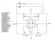
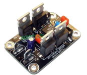
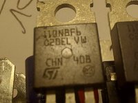
Free Technical Manual on Guitar Electronics
- Electronic Design
- 0 Replies
I have a technical manual on guitar electronics entitled "Electric-Guitar Data and Analog Circuit Collection".
It's totally free and contains lots of information not normally found in design-build books.
Electronics techs and engineers are welcome to point out any errors I may have made. Post here or email me. hkurtrichter@gmail.com
Here's the link. Onsite click "File Share" at upper left to access PDF files with various sections of the book, and other information.
https://hkurtrichter5.wixsite.com/electric-guitar-data
Rega Elicit R
- By Berkowitz
- Solid State
- 42 Replies
Hi, I have this Rega Elicit R which was bought brand new and was working ok. However, after a year of low use it started having this problem of going silent with a click following fifteen to twenty minutes of music play. If I shutdown the amp and turn it back on after a few minutes, the amp would play but again become silent with a click after a few songs.
From the beginning the unit would run pretty hot, maybe some part inside has become weak. I am currently in a country where there is no Rega service center. Let me know if anyone has any idea about what is wrong with the Amp and how to get it fixed.
Thanks.
From the beginning the unit would run pretty hot, maybe some part inside has become weak. I am currently in a country where there is no Rega service center. Let me know if anyone has any idea about what is wrong with the Amp and how to get it fixed.
Thanks.
Just another obligatory introduction ...
- By 1093i3511
- Introductions
- 1 Replies
... only that this time it's me and not another new forum member.
So, let me introduce me briefly. I'm a tinkerer out of Germany (but I do like to pretend to be out of Palau because of .... reasons) and long story short: In the last months I've switched to a low budget CLASS-D amplifier setup (Fosi Audio V3 stereo & SMSL SU-1 as a DAC) ... but as this setup won't allow me to hook up my turntable (Refurbished & upgraded Metz Mecasound TX-4963) and I still have two Marantz power amplifiers in my possession. (Marantz PM4200 & Marantz PM-35 MK.II) I simply had the idea to repurpose the old amplifiers.
As it turns out, the Marantz PM-35 MK.II has several modular PCBs instead of one all-in one PCB ... I'm currently chasing the idea to strip down the Marantz PM-35 MK.II, removing it's original PSU & power amplification board and converting it to a preamplifier or better said a input source selector & phono stage, rehousing it's guts into a smaller chassis. Instead of just buying another source selector & phono preamp (Which would be convenient, indeed. But that won't satisfy the little tinkerer inside of me.)
So my main intention to post here, is to get some help in understanding the schematics of that amplifier (available here) or at least an educated opinion if my idea is practical or does require more effort than I actually anticipate. At least with the schematics I'm currently out of my comfort zone, and therefore I'll need some advice.
Therefore, I'll open another, dedicated thread to this project. Unless someone convinces me that it's a bad idea to repurpose that old amplifier with it's MM/MC capable phono stage.
So far for now, enjoy your weekend ! It's a beautiful and sunny day where I'm at and I hope it's the same at your location !
Building an F5 Turbo v2 (in-Progress)
Building the F5 Turbo v2
This is the "in-progress" thread for the official build guide of the F5Turbo. This is not the final guide.
I am building a V2, with 2 outputs per side, source diodes, and no cascode. DIYaudio store PCB are being used and it will all go into a 5U 400mm "BIG Amp Chassis"
The Firstwatt F5 Turbo article from Nelson Pass, in case you haven't seen it - www.firstwatt.com/pdf/art_f5_turbo.pdf
Anyway, on to the build. 🙂

The Chassis in the shipping box and the PCB.
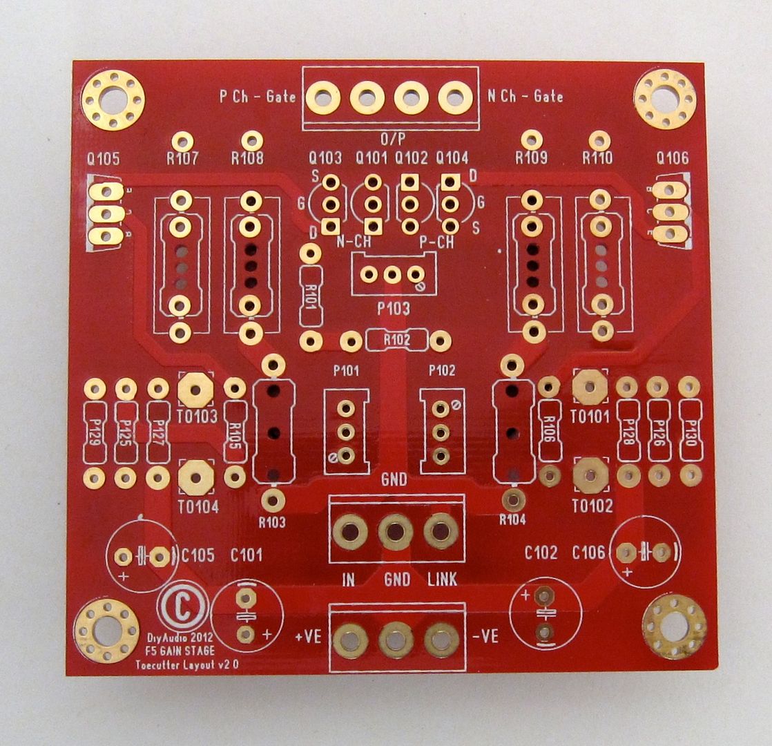
While we are at it, here is a good photo of the Front-end board
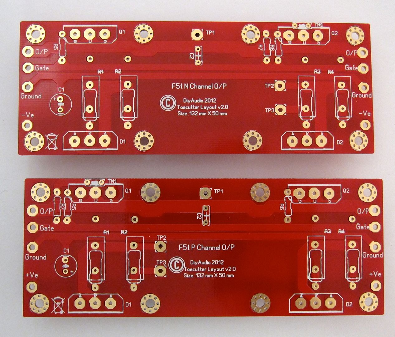
And here are the output boards. The component numbering on all these boards don't quite match up with the schematic, that will need to be clarified in the guide. In the time being, a bit of logic and inspection will let you figure it out.
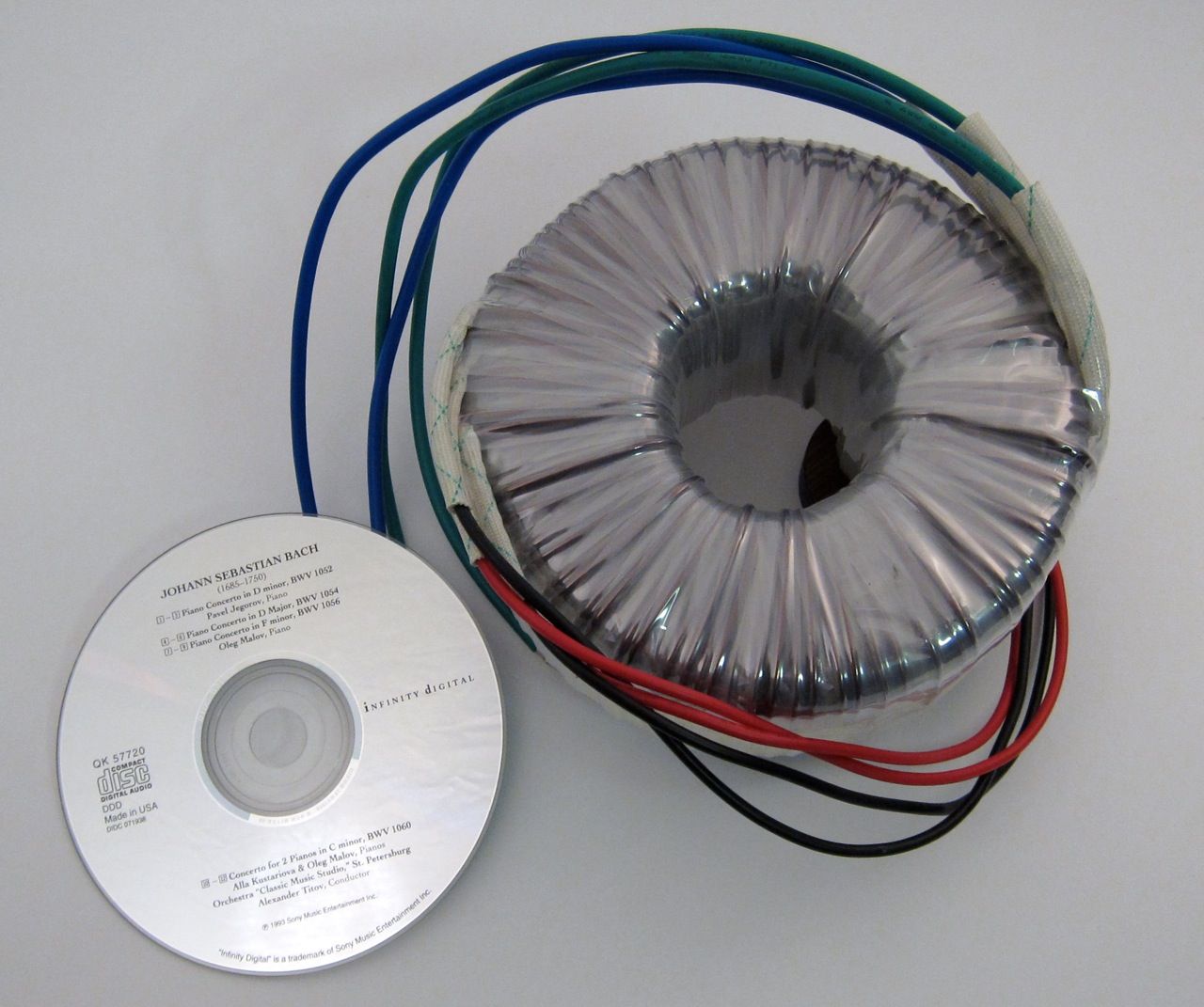
A large transformer. 🙂
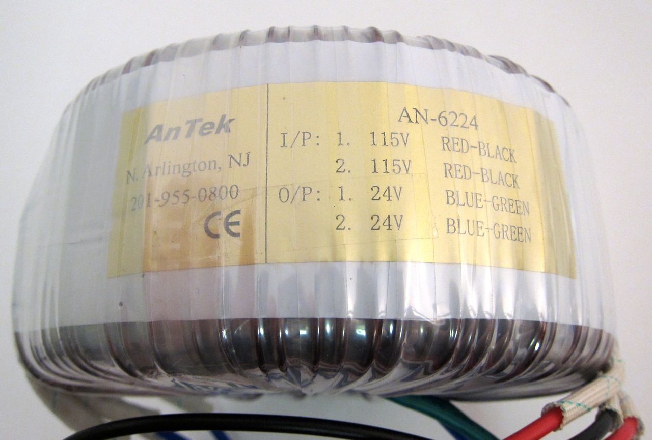
Building the PSU -
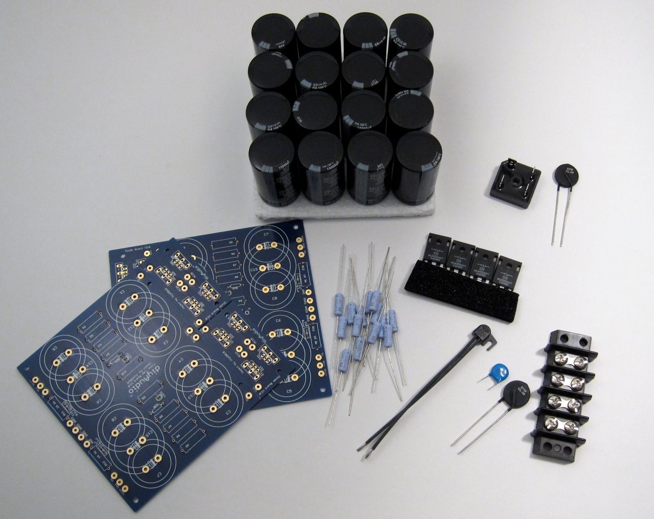
Components - PCB, Caps, resistors, thermal shutoff, inrush limiter, line cap, ground loop breaker, rectifier diodes. Not shown are rail LEDs, bleeder resistors.
Why 2 PCB? to hold the (16) 10,000uf 50v capacitors. 🙂
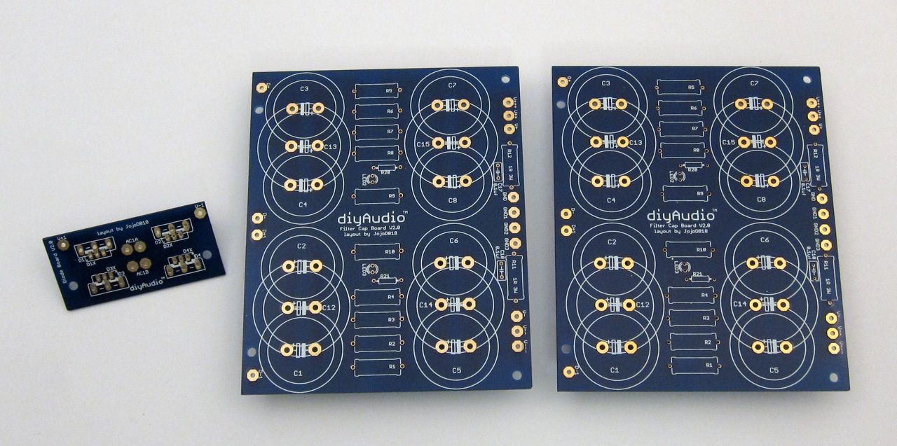
We will only need one Bridge PCB, and the rest can be cut off the boards.
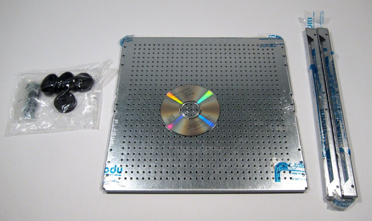
The PSU will be built on the 'DIY friendly' baseplate, shown here with some of the chassis hardware.
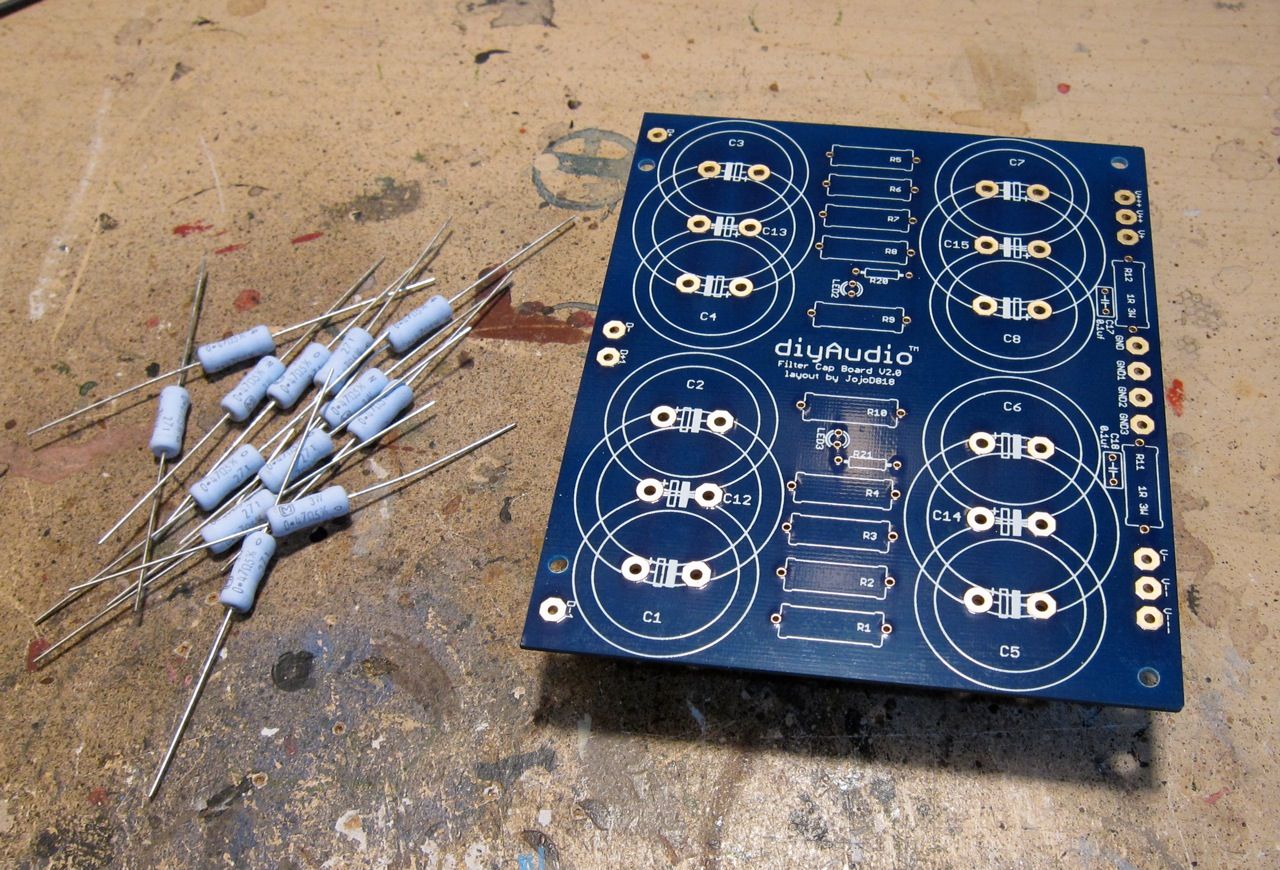
The first PCB will hold only caps and the filter resistors. But there is only room for eight, and the board holds fourteen…
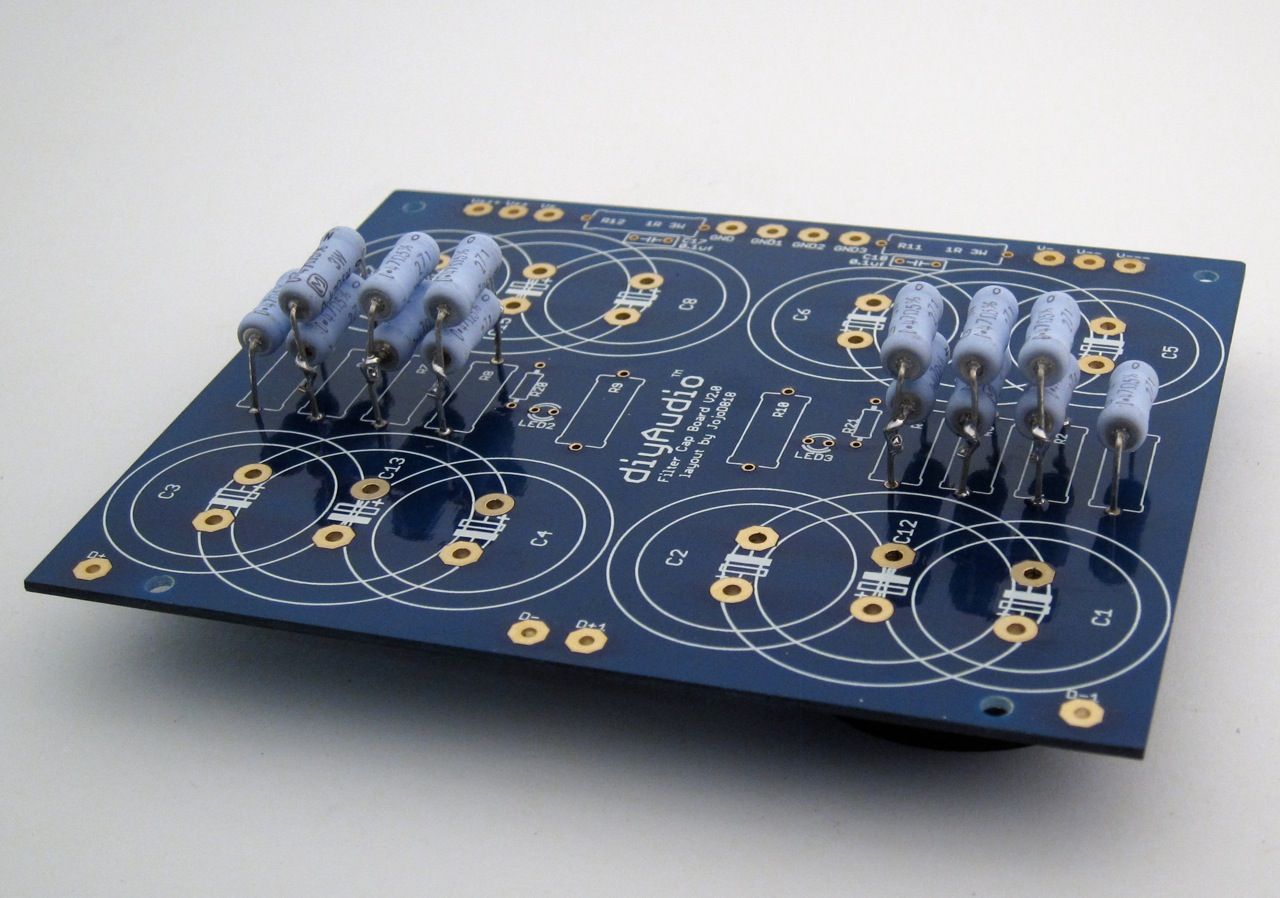
So a bit of stacking is required.
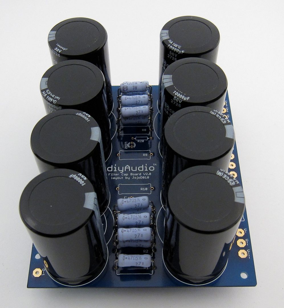
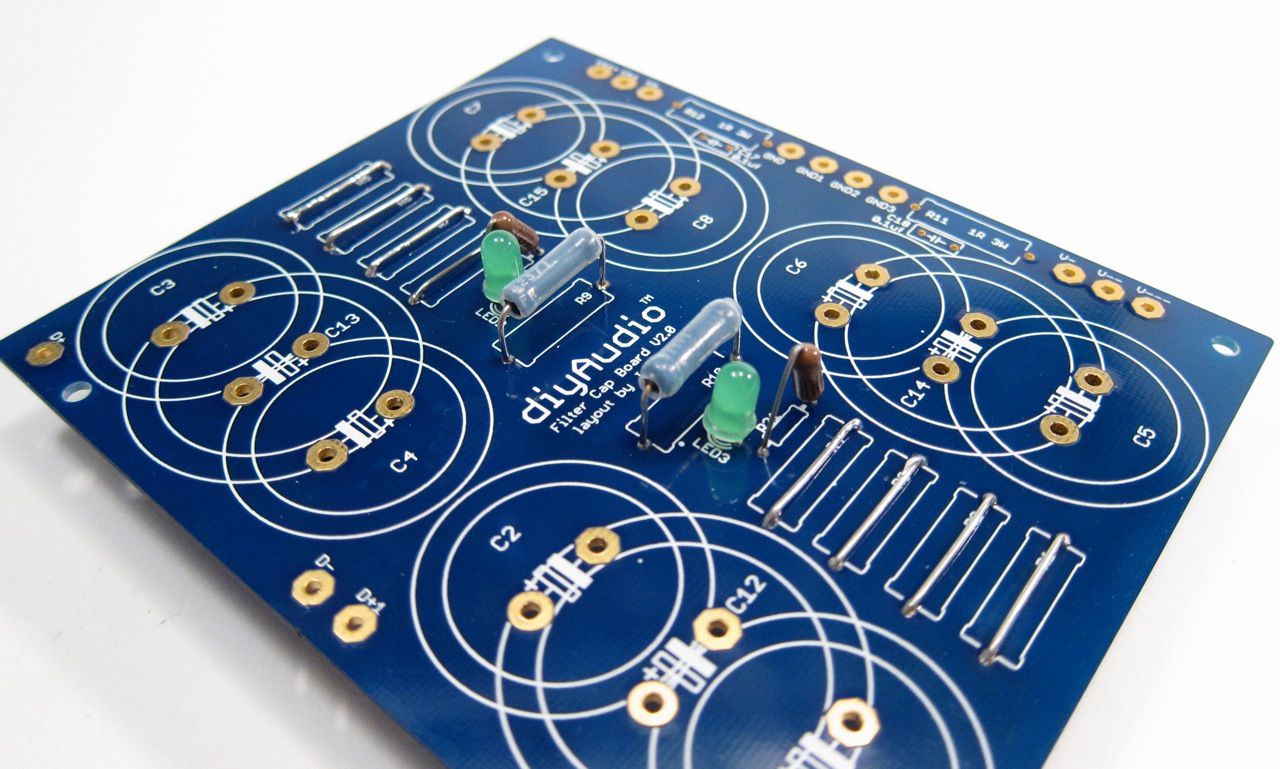
The other board will have the LEDs and bleeders. Please note that the resistor pads must be jumpered.
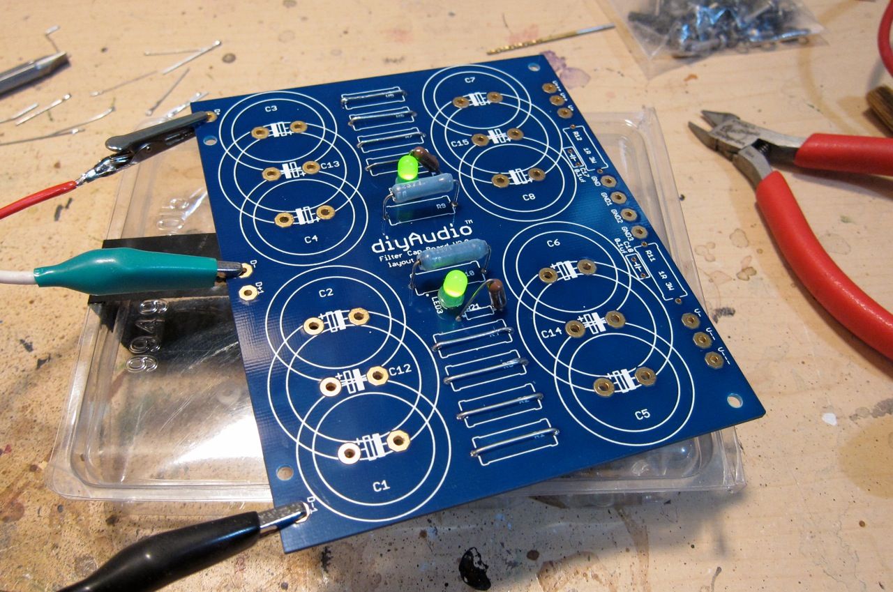
Testing the LEDs with a bench PSU
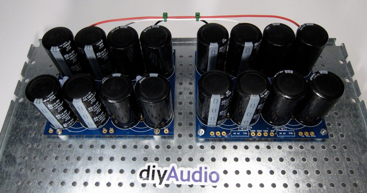
The 2 PCB now stuffed. The left will have the input from the rectifier, the right will be the output to the amp.
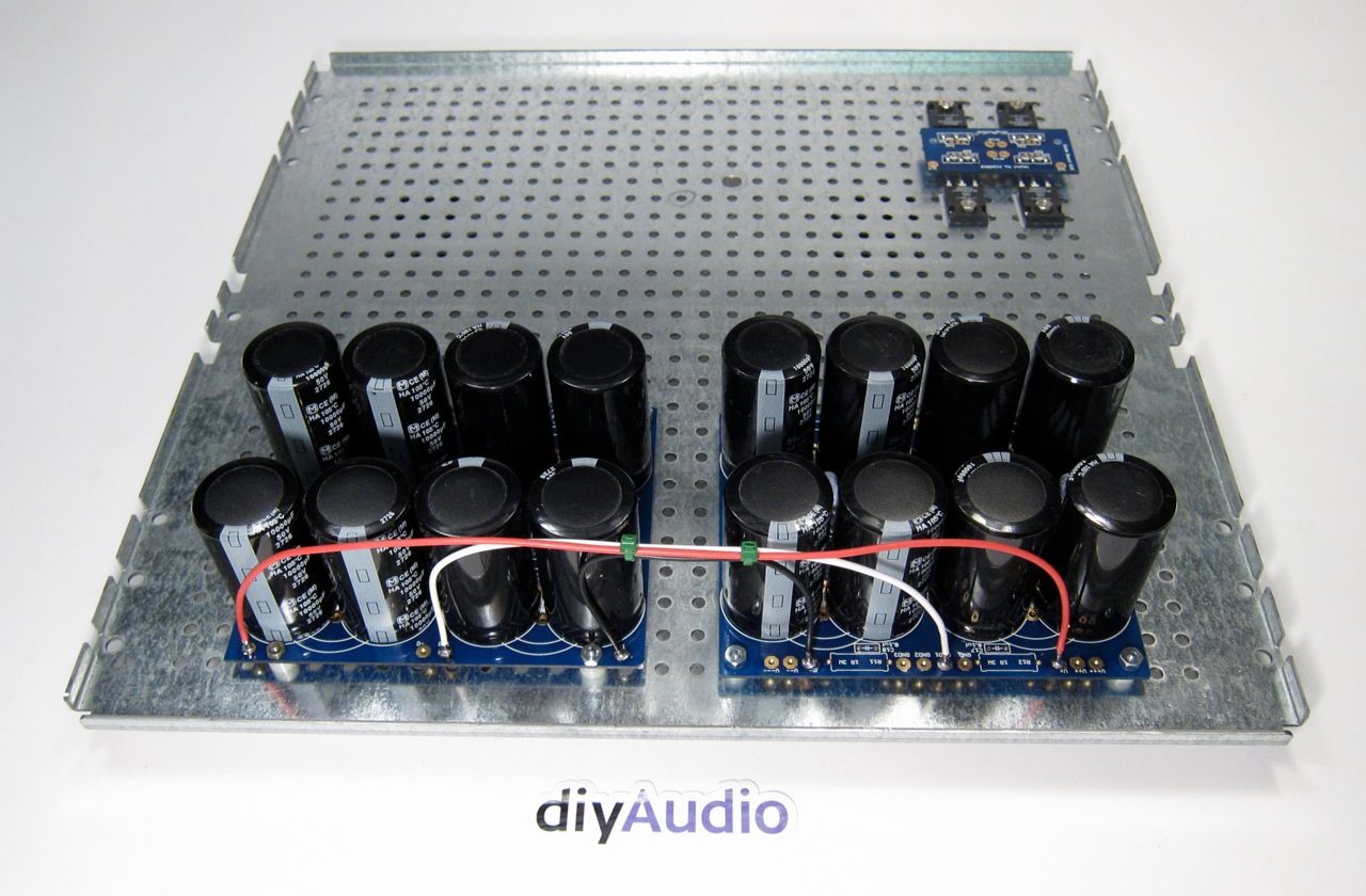
The other side of the PCBs
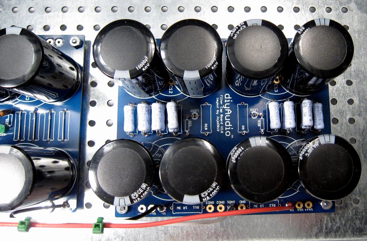
Looking down at the first PCB
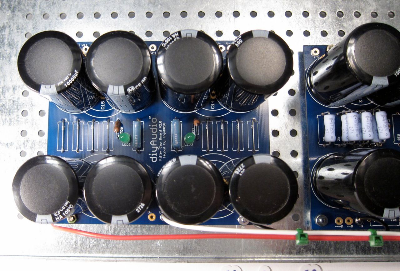
Looking at the second. Again, please note the jumpers where there are the resistors.
This is the "in-progress" thread for the official build guide of the F5Turbo. This is not the final guide.
I am building a V2, with 2 outputs per side, source diodes, and no cascode. DIYaudio store PCB are being used and it will all go into a 5U 400mm "BIG Amp Chassis"
The Firstwatt F5 Turbo article from Nelson Pass, in case you haven't seen it - www.firstwatt.com/pdf/art_f5_turbo.pdf
Anyway, on to the build. 🙂
The Chassis in the shipping box and the PCB.
While we are at it, here is a good photo of the Front-end board
And here are the output boards. The component numbering on all these boards don't quite match up with the schematic, that will need to be clarified in the guide. In the time being, a bit of logic and inspection will let you figure it out.
A large transformer. 🙂
Building the PSU -
Components - PCB, Caps, resistors, thermal shutoff, inrush limiter, line cap, ground loop breaker, rectifier diodes. Not shown are rail LEDs, bleeder resistors.
Why 2 PCB? to hold the (16) 10,000uf 50v capacitors. 🙂
We will only need one Bridge PCB, and the rest can be cut off the boards.
The PSU will be built on the 'DIY friendly' baseplate, shown here with some of the chassis hardware.
The first PCB will hold only caps and the filter resistors. But there is only room for eight, and the board holds fourteen…
So a bit of stacking is required.
The other board will have the LEDs and bleeders. Please note that the resistor pads must be jumpered.
Testing the LEDs with a bench PSU
The 2 PCB now stuffed. The left will have the input from the rectifier, the right will be the output to the amp.
The other side of the PCBs
Looking down at the first PCB
Looking at the second. Again, please note the jumpers where there are the resistors.
Create 3D model of components for EasyEDA?
- By Mimiragon
- Software Tools
- 2 Replies
Good evening, I was looking for some information, in particular if anyone ever created a 3D model for making a custom component in EasyEDA.
I would like to know the 3D/CAD program best suited for this.
I know how to use Blender3D quite well but I have no idea if it's possible to later on import it into EasyEDA easily, one would think that solidworks/autodesk fusion would be more suited for this. Did anyone ever try?
Regards.
I would like to know the 3D/CAD program best suited for this.
I know how to use Blender3D quite well but I have no idea if it's possible to later on import it into EasyEDA easily, one would think that solidworks/autodesk fusion would be more suited for this. Did anyone ever try?
Regards.
Can you build like this power supply ?
- Construction Tips
- 8 Replies
Although the regulation circuit is physically connected to the incoming mains, it is disconnected electrically. A monitoring circuit detects the portion of the sine wave that is charging the first of a pair of electrolytic capacitors. Once this first capacitor is fully charged, the diode bridge rectifier turns off and a mosfet switching circuit transfers the charge from the first cap to the second. This cycle is repeated continuously.
Output voltage: -0V - +22Vdc, 0V - -22Vdc
Output voltage: -0V - +22Vdc, 0V - -22Vdc
- Output current: +/- 0.5 amps dc
- Mains: 3 Pin IEC moulded (socket on rear)
- Mains Voltage: 230Vac
Notch filter + Zobel sanity check
- By Groundloops
- Multi-Way
- 4 Replies
Enclosed are files of a VituixCAD simulation of a notch filter and a Zobel element - I want to tame the breakup modes of an actively driven Purifi PTT6.5X04-NAA-08 6.5” aluminum midwoofer. Is my approach okay? Thanks for your contribution!

Attachments
How do people attach panel-mount LEDs to thick front panels
- Construction Tips
- 16 Replies
I like putting handsome indicator LEDs like the one below on the front panel of stuff I build.

But I also like those lovely 10mm thick brushed aluminum front panels from Modushop.
Problem is: I’ve not yet found an indicator LED with threads long enough to reach all the way through the 10mm panel. On my last amp I drilled out a massive hole to fit the nut into. It’s still very hard to fasten & unfasten the LED.
How do you folks attach panel-mount LEDs to thick front panels? Or do you? Hs anyone found a panel-mount with 12mm thread? Snap-ins that work? What about T-nuts which can be turned with a wrench?
Any clever ideas?
Tube tester recommendations?
- By fixessaxes
- Equipment & Tools
- 12 Replies
Hello all,
I apologize for what is likely a duplicate post, but I am unable to post in the tubelab forum (which is why I registered) until I generate "four meaningful posts" so I am trying to come up with questions to ask- even though my first inclination is to watch and search and lurk!
I am considering buying a tube tester to make my future hobby a bit easier. First thing I am working on is a StroboConn tuner (a bit odd, but it will be useful at my job) and it has the original Conn (re)branded tubes I would love to keep and even use, if they are working right. I can drive a few hours to a friend's place to use his tube tester, but it seems like I might want one for myself if they are not too much of a can of worms.
Questions: Any recommendations? Hickok seems to be a standard. Are there ones to avoid? What should be expecting to pay? Are they easy to fix if they are not in perfect condition? What sorts of issues should I expect, or look out for? Where to buy? I've been looking at ebay. Any recommendations or words of wisdom?
Thank you for your time, and again, sorry if this is a duplicate post but I am unable to post in the tubelab forum until I engage more.
Hello
- Introductions
- 2 Replies
Hello, I'm Allen I like DIY Hifi DAC and UAC2 interface . I found in diyAudio forum there are so many people like me .
People here are kind and discuss technical freely . I'd like to join the group.
People here are kind and discuss technical freely . I'd like to join the group.
Can't upload pictures
- By spedge
- Forum Problems & Feedback
- 4 Replies
I have tried to upload pictures from my phone but the picture does not show in the picture box in the file attachment.
Is this a known problem.
Steve.
Is this a known problem.
Steve.
How does a audio transformer keep frequency response flat
- By Mrdouble
- Electronic Design
- 3 Replies
I'm working with a audio isolation transformer and it hit me, how exactly does a audio transformer maintain a flat frequency response when by definition an inductor is frequency dependent. I'm guessing its a simple answer and I Googled it but no good hits. Ether way, I thought it was an interesting question.
Thanks
Micheal
Thanks
Micheal
Replacing tweeters on Beovox penta speakers?
- By MaxExcursion
- Multi-Way
- 7 Replies
These are the MK2 version i believe (From 1987). It's common to re-foam the midranges on these, also common to re-cap the massive crossovers. Both of which I've already done to mine!
But upon removing the tweeters, i noticed a strange brown stain on the stickers that show the brand name... I couldn't help myself, and took one of them apart very carefully, and guess what? Ferrofluid! Nasty, crusty old ferrofluid to be precise.
I tried asking around, and of the many people that work on these towers, NOBODY i asked knew that those tweeters used ferrofluid. I even emailed B&O, and they were surprisingly helpful! But even they had no real idea on how much fluid went into those tweeters. So i'm looking to just swap them out with more modern ones.
Turns out, this isn't as simple as it sounds. I've had replies going from "just buy some cheap tweeters and slap them on, you might get lucky!" all the way to very scientific replies that i barely understood...
They are ferrite, silk-dome tweeters. No idea what brand tho, the midrange drivers can be made by Nokia, SEL or ITT. Depending on the position of the moon it seems... I have a suspicion that the tweeters are made by SEAS tho.
So, what are my options here? Just eyeball the ferrofluid and hope for the best? Or try to replace them with modern tweeters, without knowing a damn thing about the specs of the old ones?
As i'm typing this, i'm also going to send an email to the owner of Audiofriends. I've bought all my Penta repair stuff from them, perhaps they'll know the true specs of the tweeters.
Any input is appreciated!
CDM2 Servo Board. How to identify the version when the stickers are gone.
- By rockrink
- Digital Source
- 0 Replies
I have on the bench a Conrad Johnson SD-1. It is based on the Magnavox FD2041. All the literature I can find says it uses a standard CDM2 transport. This one has no stickers on it and I am trying to determine which Pre-amp Servo board is in use. Virtually every SM I have read shows a 1K laser output adjustment pot at 3106. This board has a 4.7K pot. I have seen that pot used in CDM4 but not CDM2 before. I am trying to determine which version of the board this is. I attach a picture and wonder if anyone has any insight.
Attachments
Hello
- By Skylight67
- Introductions
- 1 Replies
Hi, just got into diy stuff with audio and need some help!
Versatile audio load bank
- By rayma
- Equipment & Tools
- 1 Replies
This five resistor load bank can be adapted for audio by dividing all of the resistor values by 100.
Then the values are 10 ohms each, and the total load can be adjusted among 12 values, from 20R to 2.5R.
Choose the power rating of the resistors for your needs..
https://www.electronicdesign.com/re...step-resistor-load-bank-is-simple-and-modular
Then the values are 10 ohms each, and the total load can be adjusted among 12 values, from 20R to 2.5R.
Choose the power rating of the resistors for your needs..
https://www.electronicdesign.com/re...step-resistor-load-bank-is-simple-and-modular
For Sale Hitachi MosFET 2SJ50 & 2SK135
I have 21 x 2SJ50 HITACHI and 22 x 2SK135 HITACHI. They are around 30 years old and have not been used since then. These lateral Fets are fames in many amplifier output stages. Minimum purchase is 4 pairs of Mosfets. Offers are welcome. Clear up my semiconductor collection of the ones I don't need anymore.
The price does not include PayPal and shipping costs. Can only shipped from Germany , prices are much lower above 200gr Parcel weight. PayPal is accepted, only registered shipping possible, the buyer pays the additional 5% PayPal fees, a payment as PayPal / friend does not account for the 5% and can be shipped without tracking, the shipping costs within the EU are about €15 - €17. Outside the EU it may vary by country. A combined shipping is possible but will change the shipping costs a bit. If you are interested send me a PM.
The price does not include PayPal and shipping costs. Can only shipped from Germany , prices are much lower above 200gr Parcel weight. PayPal is accepted, only registered shipping possible, the buyer pays the additional 5% PayPal fees, a payment as PayPal / friend does not account for the 5% and can be shipped without tracking, the shipping costs within the EU are about €15 - €17. Outside the EU it may vary by country. A combined shipping is possible but will change the shipping costs a bit. If you are interested send me a PM.
Attachments
-
 Hitachi J50 K135 (1).jpg338.3 KB · Views: 257
 -
 Hitachi J50 K135 (2).jpg218 KB · Views: 352
 -
 Hitachi J50 K135 (3).jpg310 KB · Views: 294
 -
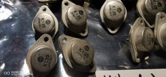 Hitachi J50 K135 (4).jpg303.3 KB · Views: 298
 -
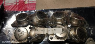 Hitachi J50 K135 (5).jpg355.3 KB · Views: 301
 -
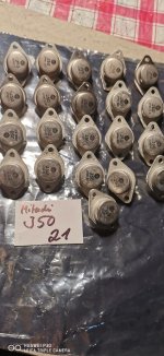 Hitachi J50 K135 (6).jpg324.5 KB · Views: 195
 -
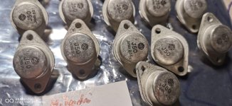 Hitachi J50 K135 (7).jpg258 KB · Views: 209
 -
 Hitachi J50 K135 (8).jpg223.5 KB · Views: 180
 -
 Hitachi J50 K135 (9).jpg206.7 KB · Views: 176
 -
 Hitachi J50 K135 (10).jpg293.9 KB · Views: 201
 -
 Hitachi J50 K135 (11).jpg366.7 KB · Views: 237
 -
 Hitachi J50 K135 (12).jpg266.3 KB · Views: 190
How to beautifully photograph silicon chips in DIY style?
- By IVX
- Equipment & Tools
- 53 Replies
Many of us have a stereo microscope for soldering SMD, and the first idea comes to use that to inspect silicon chips and transistors to make sure it is not fake and the same version of what you are looking for. However, the result is always awful, and how can I see now, the reason is a coaxial light option which is unavoidable and needed to get perfect pics of silicon. The magnification factor nearly doesn't matter, my stereo Nikon SMZ660 has 300x max but still sucks due to LEDs light falling with not 90 degrees - glossy reflections ruining the picture contrast.
So, Is there any chance to get nice pics without $5000 Zeiss metallurgical microscope? Hell yeah, quite compact and within $100! First I bought a used VSZ-0530CO Japanese precision optical zoom device $53(with 12V coax LED!), it is a machine vision element massively used in China to control production parameters and measure dimensions. Vital Vision Technology promises a good resolution(4um) and minimal geometric distortions(.001) for the device, you need just add the C-mount CMOS camera 1/1.8"(from $30 for a secondhand) and 160mm RMS standard 4X lens aka objective(I paid $8 for used Canadian Motic EF plan 4X/0.1) with a thread adapter($4). The small like a book table + holder cost me $15, that's it. Check this out:

Low phase-noise EPSON_SG-210STF oscillator chip.

BC856B

AD8397 is a bit dirty with the residual plastic on the silicon.

Ti ISO7240

OPA1612 has such a tiny marking, the symbol's thickness is 4um, and the minimal visible elements are 1.5um. That pic taken with Motic 40X lens.

And a short video 30fps 400X, to see how that looks online.
So, Is there any chance to get nice pics without $5000 Zeiss metallurgical microscope? Hell yeah, quite compact and within $100! First I bought a used VSZ-0530CO Japanese precision optical zoom device $53(with 12V coax LED!), it is a machine vision element massively used in China to control production parameters and measure dimensions. Vital Vision Technology promises a good resolution(4um) and minimal geometric distortions(.001) for the device, you need just add the C-mount CMOS camera 1/1.8"(from $30 for a secondhand) and 160mm RMS standard 4X lens aka objective(I paid $8 for used Canadian Motic EF plan 4X/0.1) with a thread adapter($4). The small like a book table + holder cost me $15, that's it. Check this out:
Low phase-noise EPSON_SG-210STF oscillator chip.
BC856B
AD8397 is a bit dirty with the residual plastic on the silicon.
Ti ISO7240
OPA1612 has such a tiny marking, the symbol's thickness is 4um, and the minimal visible elements are 1.5um. That pic taken with Motic 40X lens.
And a short video 30fps 400X, to see how that looks online.
Attachments
Ripple current PSU caps vs other characteristics
- By poirson
- Power Supplies
- 8 Replies
Hello,
I build tube amps for fun. I wonder about the origin of the components, I live in France. For electrochemicals there is F&T, but the ripple current and the lifespan are much lower than Pana ED model 47uF for exemple.
I am attaching a 5E3 type diagram to have a power supply in front of me.
What characteristics would be preferred please?
Tell me more !
Pana ED
https://fr.rs-online.com/web/p/condensateurs-electrolytiques-aluminium/4340380?gb=s
https://www.mersen.com/fr/produits/condensateurs
Attachments
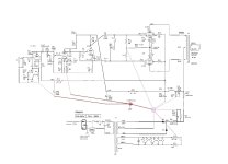
5 VDC heater supply from 6.3 VAC filament
- By thuanth43
- Power Supplies
- 5 Replies
So I have this transformer that has 2x 6.3vac/5A + 2x 6.3vac/1.5A and am wiring it to have 2x 6.3vac/6.5A.
I plan to use the LT1083 to regulate to 5vdc and feed 2x 300B per channel. It's a 4x 300B P-P amp.
I wonder if my plan is feasible or the 6.3vac is a bit too low for 5vdc output?


I plan to use the LT1083 to regulate to 5vdc and feed 2x 300B per channel. It's a 4x 300B P-P amp.
I wonder if my plan is feasible or the 6.3vac is a bit too low for 5vdc output?
For Sale VIFA D26TG-35-06 Tweeters x 2
I have two Vifa D26TG-35 tweeters for sale. These have been in storage for quite a while, but works ok. $150 for both + postage. Located in Australia, but can ship to anywhere if postage is covered.


Heat Sink & Thermal dissipation, some calculations if interesting to some
Following previous posts on the “Ship of Theseus” thread around here https://www.diyaudio.com/community/...ngeable-amplifier-modules.383745/post-7437999 [stopping to avoid derailing the specific amp topic], here is a follow-up, in the Parts section, which might be more appropriate: heatsink = parts
The post shall serve as a reminder for myself, and maybe it would be usefull to others at some point.
After the original posts, here is what I learned
A. [from a discussion with a thermal engineer @work]
Outside heat exchange coefficient of h=20 w/(m²-C) was probably too optimistic. h=15w/(m²-C) might be better
B. [from the same discussion]
*Imposing temperature is like imposing a constraint for a mechanical calculation. It is better to impose a thermal power released by the transistor to calculate a state of equilibrium between power released by the transistor and power dissipated by the heatsink.
*He suggested Thermal Power = Electric Power as a starting point.
*Since M. Johnson indicated that each transistor of the Theseus should give about 30watts (approximation), I set a thermal flux of 93750 watt/m² for each roughly 20mm*16mm transistor surface. 93750*0.020*0.016=30.
C. [air temp measurement with an M2x 4U 400mm]
Different circuit & heatsinking, but it is what I have
Ambiant air temp: around 20/25degrees
Air temp inside the amp after 1h: 45degrees
Air temp between the fins after 1h: 35degrees.
This to put an approximation of temperature for the convection in the various calculation. (I was using much higher inner air temp: 65degrees before)
Using this with the “Ship of Theseus” reference, transistor located on the left side (6L6 here https://www.diyaudio.com/community/...ngeable-amplifier-modules.383745/post-6958070), leads to the following results (picture)
What is worth noting is the different in temperature between the 2 transistor surfaces, the one on the right being colder, most probably because he “sees” a bigger chunk of the heatsink.
Lower temperature of 42degrees indicates that the heatsink participate to cooling the inside (I guess)
Attachments
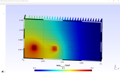
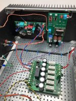
Grado ME+ Mono
- By R1234
- Analogue Source
- 6 Replies
I have a grado ME+ mono for playing 50's+ mono LP's & have a few different arms from older Ortofons, an SME 3012 to a formula 4 unipivot. Also an LP 12 with a Fidelity Research arm.
I assume the heavier arms would be better. - This for playing a good classical LP colection in VG condition from my father, - Decca's, Mercury, Phillips, RCA etc.
Any comments?
Thanks,
R.
I assume the heavier arms would be better. - This for playing a good classical LP colection in VG condition from my father, - Decca's, Mercury, Phillips, RCA etc.
Any comments?
Thanks,
R.
JLH 10 Watt class A amplifier
- By tschrama
- Solid State
- 9818 Replies
Well... just a thread to say that at last I finished my JLH 10Watter last weekend... I dicided to buy a commercial lab-powersupply.. this made things alot easier..
The results: Great!
Sound is a difinite upgrade from my Sony integrated amp .. more instruments are comming through even in loud part of the music.. high's are excelent .. well at least for me they are.. and supprisingly the bass somehow has more detail.. I experienced the new sound like I experinced my first Grado headphone listeing, but now with the stereophonic effect working..
The amp was easy to build, I even flipped a transistor around but the amp still worked.! just a little noisy.. Iq is set at 1.2A@ 27Volt, the 4 heasinks get hot but can be touched for more than 10 seconds.. well permanent actually higher voltages and Iq goes really hot!
10Khz square wave looks crystal clean but a 50KHz reveals the assymetric slewrate.. bandwidth goes from 10Hz to beyond 200KHz...
conclusion are that it is a very simple amp to build, no PCB used, no instability of any kind.. and sound is quite revealing.. highly recommended
but then again, my initials aren't H.H. 😉
OPA627 question
- By Hierfi
- Solid State
- 45 Replies
I want to examine the sonic virtues (?) of an OPA627 for myself, however genuine OPA627's "seem" getting hard to find at less than $40 each from Digikey. To test the parts out what is the resistance between pin 5 and pin 7 of a genuine part? Pin 5 is normally one of the input terminals for an external offset trimmer (the other is pin 1 as ought to have the same resistance value). Both ought to be connected to the positive supply if the part is genuine.
Thus far alleged "genuine" parts have resistances connected to the negative rails, or appear on the wrong pins.
Thus far alleged "genuine" parts have resistances connected to the negative rails, or appear on the wrong pins.
SunValley P1616D Power AMP
This is a self-bias amplifier that allows you to replace beam tubes and pentodes from 6L6GC to KT170 without any adjustments.
Equipped with an output transformer from Hashimoto Electric, a proud Japanese manufacturer, and a V-Cap coupling capacitor, this lavish upgrade promises high performance and sound quality that far exceeds the original model.
Maximum output is 40W for KT88 and 45W for KT170, and it operates in Class A at regular levels, with a focus on sound quality.
This is a high-cost performance model that allows you to enjoy the essence of Japan quality, with a high signal-to-noise ratio, wide frequency response, and excellent damping characteristics.
SV-P1616D/VK Pentode Power-amplifier
Hashimoto version HW-40-5 kit 120V/240V
NO Volume Pot
Point to Point assembly
The production version will get rid of the volume port and replace the stock opt to Hashimoto H40-5
KT170×4 ECC81/12AT7×2 ECC82/12AU7×2 ※Tube set is an option
Rated output: UL connection (Class A operation up to 50% of rated output)
(8Ω、THD:10%)
KT170 45W+45W
KT150 37W+37W
KT120 37W+37W
KT88 35W+35W
EL34 33W+33W
KT66 25W+25W
6L6GC 22W+22W
Frequency reponse :5Hz~150kHz(1W/8Ω/-3dB)
Gain:27~29dB(8Ω)
size in mm:W365×D300×H190

You will notice that the output transformer has been replaced by Hashimoto HW-40.
All aeesembled version be will instaled with 4X Vcap ODAM coupling caps
Pricing
KIT $2,150 (point to point kit)
Assembled $2,750 (Made and Assembled in Japan with 4 VCAPs ODAM)
TUBE SET EXTRA
It would be premature to think that anyone can just change the OPT... The output transformer affects the overall characteristics as much as a car engine. In cases such as a single triode with no feedback, it may be possible to replace it by checking the impedance and core capacity, but in the case of a push-pull amplifier with a large amount of feedback, in the worst case scenario, the amplifier may oscillate and be damaged, so careful consideration in advance and detailed measurements after replacement are required.The original output transformer is a custom-made product (made in Japan) optimized for the SV-P1616D and has KNF (cathode NF) windings, but the OPT to be installed this time does not have KNF windings. NFB is established based on the delicate balance of the amplifier, so the design is very delicate and design changes are required.
According to the report of the craftsman who was commissioned to make the prototype, the default NF resistor and phase compensation capacitor capacitance caused oscillation outside the audible range. This is something that cannot be detected by ear and can only be detected by measurement, so special care is required. As a result, integral compensation was added to the secondary side of the OPT to ensure stability and the project was completed.

I accept preorder
FreeDSP-G
- By CyberPit
- Digital Line Level
- 10 Replies
A Happy New Year to all.
I decided to start a new project, called "FreeDSP-G" as an Electric Guitar Amplifier Simulator Project.
I previously tested the Amp-Simulator implementation on FreeDSP-OCTAVIA. It was good to learn the potential of SigmaDSP processing. The most critical point was the available number of control pots. However, multiplexing AUXADC will solve the issue. So, I established a concept design drawing as below.

ADAU1467 will fit this project. It has 8 AUXADC and additional many GPIOs.
CyberPit
I decided to start a new project, called "FreeDSP-G" as an Electric Guitar Amplifier Simulator Project.
I previously tested the Amp-Simulator implementation on FreeDSP-OCTAVIA. It was good to learn the potential of SigmaDSP processing. The most critical point was the available number of control pots. However, multiplexing AUXADC will solve the issue. So, I established a concept design drawing as below.
ADAU1467 will fit this project. It has 8 AUXADC and additional many GPIOs.
CyberPit
Stupid ATH Tricks
- Multi-Way
- 3 Replies
David Lettermen used to have a feature on his Late Night Show called "Stupid Pet Tricks." It's basically what it sounds like; pets doing pointless things.
Something I've noticed in my experiments with ATH, is that my results generally pale in comparison to everyone else, but I'm often doing strange things with the waveguide, just to see what happens.
It's hard to track my weird experiments in the main ATH thread, because there's so much traffic. I made the posts and I often have a hard time finding my own posts.
So I thought it might be fun to post some weird ATH waveguides, basically to evaluate what would happen if you made something strange.
Over the years, I've struggled to make a waveguide with a diffraction slot that actually works; most of my experiments with ATH and IRL haven't really panned out. Diffraction slots have a LOT of issues.
Then again, I found that triangular waveguides work shockingly well, even though I've never seen anyone actually build one IRL.
Noob build, Help me choose a Fonken!
- By NoahBA
- Full Range
- 36 Replies
Hello All,
I’ve been doing a lot of reading on the forum the last few weeks, and I first want to thank all the contributors for the wealth of knowledge here. Amazing online community!
I got a pair of blumenstein orcas last year to go with my Bottlehead SEX, 2wpc set amp. I am digging the low power-single driver sound! But when I moved from near field into a larger room (270 ft2, 12ft ceiling) they started to feel too “small”. I don’t have an extensive audio vocab, but I believe I want more bass extension and higher sensitivity, all in a smallish package (can be bigger than orca though). Seemed too much to ask, but after some reading I fell in love with the OG Fonken with fe127e driver. However the drivers are no longer available, and it seems Ff125wk may not be sensitive enough for my flea powered amp. I am eventually looking at adding a sub.
Any suggestions? Or anybody have the old model driver laying around?
Thank you,
Noah
NAD T751 low output issue
- By jvoid22
- Solid State
- 19 Replies
Hello all, so I had the output on the T751 drop to nearly nothing. There was a previous issue and I replaced the surround board. Everything worked fine since then.
I just decided to try and fix the new issue and am stuck.
I re-capped the entire front amp board.
I pulled each of the main transistors at the bottom and they all seemed to test OK off board.
I seem to be getting proper voltage at the opamp on the load board, and proper voltage out to the front amp board. If I turn the volume up very high, I can hear the source a bit, but it's very faint.
Problem persists through headphones.
Sound completely gone if I change listening mode to anything but stereo.
I'm not sure where I should be focusing my effort now. There are a bunch of smaller transistors on the board I didn't check yet as it would be pretty time consuming to take them all out of circuit.
Any direction would be appreciated
Attachments
Hello
- By Alemaker7578
- Introductions
- 3 Replies
Hello, I am 53 years old and came across this forum while researching and trying to get a better understanding of audio amplifiers.
I love restoring vintage electronic/electrical items in hopes of "bringing it back", repurposing and keeping
it out of the landfill. Thanks for such a great website!
p.s.- The more I think I know, the more I realize how much more there is to learn..
I love restoring vintage electronic/electrical items in hopes of "bringing it back", repurposing and keeping
it out of the landfill. Thanks for such a great website!
p.s.- The more I think I know, the more I realize how much more there is to learn..
Load more
Projects by fanatics, for fanatics
Get answers and advice for everyone wanting to learn the art of audio.
Join the Community
508,468
Members
7,920,952
Messages