Following previous posts on the “Ship of Theseus” thread around here https://www.diyaudio.com/community/...ngeable-amplifier-modules.383745/post-7437999 [stopping to avoid derailing the specific amp topic], here is a follow-up, in the Parts section, which might be more appropriate: heatsink = parts
The post shall serve as a reminder for myself, and maybe it would be usefull to others at some point.
After the original posts, here is what I learned
A. [from a discussion with a thermal engineer @work]
Outside heat exchange coefficient of h=20 w/(m²-C) was probably too optimistic. h=15w/(m²-C) might be better
B. [from the same discussion]
*Imposing temperature is like imposing a constraint for a mechanical calculation. It is better to impose a thermal power released by the transistor to calculate a state of equilibrium between power released by the transistor and power dissipated by the heatsink.
*He suggested Thermal Power = Electric Power as a starting point.
*Since M. Johnson indicated that each transistor of the Theseus should give about 30watts (approximation), I set a thermal flux of 93750 watt/m² for each roughly 20mm*16mm transistor surface. 93750*0.020*0.016=30.
C. [air temp measurement with an M2x 4U 400mm]
Different circuit & heatsinking, but it is what I have
Ambiant air temp: around 20/25degrees
Air temp inside the amp after 1h: 45degrees
Air temp between the fins after 1h: 35degrees.
This to put an approximation of temperature for the convection in the various calculation. (I was using much higher inner air temp: 65degrees before)
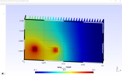
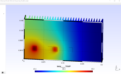
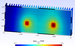
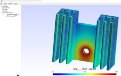
Using this with the “Ship of Theseus” reference, transistor located on the left side (6L6 here https://www.diyaudio.com/community/...ngeable-amplifier-modules.383745/post-6958070), leads to the following results (picture)
What is worth noting is the different in temperature between the 2 transistor surfaces, the one on the right being colder, most probably because he “sees” a bigger chunk of the heatsink.
Lower temperature of 42degrees indicates that the heatsink participate to cooling the inside (I guess)
The post shall serve as a reminder for myself, and maybe it would be usefull to others at some point.
After the original posts, here is what I learned
A. [from a discussion with a thermal engineer @work]
Outside heat exchange coefficient of h=20 w/(m²-C) was probably too optimistic. h=15w/(m²-C) might be better
B. [from the same discussion]
*Imposing temperature is like imposing a constraint for a mechanical calculation. It is better to impose a thermal power released by the transistor to calculate a state of equilibrium between power released by the transistor and power dissipated by the heatsink.
*He suggested Thermal Power = Electric Power as a starting point.
*Since M. Johnson indicated that each transistor of the Theseus should give about 30watts (approximation), I set a thermal flux of 93750 watt/m² for each roughly 20mm*16mm transistor surface. 93750*0.020*0.016=30.
C. [air temp measurement with an M2x 4U 400mm]
Different circuit & heatsinking, but it is what I have
Ambiant air temp: around 20/25degrees
Air temp inside the amp after 1h: 45degrees
Air temp between the fins after 1h: 35degrees.
This to put an approximation of temperature for the convection in the various calculation. (I was using much higher inner air temp: 65degrees before)
Using this with the “Ship of Theseus” reference, transistor located on the left side (6L6 here https://www.diyaudio.com/community/...ngeable-amplifier-modules.383745/post-6958070), leads to the following results (picture)
What is worth noting is the different in temperature between the 2 transistor surfaces, the one on the right being colder, most probably because he “sees” a bigger chunk of the heatsink.
Lower temperature of 42degrees indicates that the heatsink participate to cooling the inside (I guess)
Attachments
Then, redoing different calculations, with 6L6 amp used as a reference for comparison, i have
Thermal Power @transistor 30Watts | | | | |
Setup | Tmax | Tmin | Tmax Vertical (High) | Tmax Vertical (Low) |
Reference Theseus 4U (6L6) | 55.3 | 41.4 | 47.9 | 51.4 |
Theseus 4U Mosfets@Center | 52.5 | 43.5 | 45.7 | 48.8 |
Theseus 3U Mosfets@Center (to build?) | 56 | 46.5 | 50.8 | 52.2 |
AlephJ 4U (if 1 Transistor=30w) | 63.4 | 53.5 | 55.1 | 59.7 |
Aleph20 3U Ranshow (if 1 Trans=30w) | 71.1 | 59.7 | 68.3 | 68.3 |
Attachments
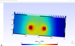

So, compared to the 6L6 placement of the transistors on the left side of the 4U-300mm heatsink, a 3U-300mm with mosfets in the middle/centered would:
a. have a Max Temperature only 0.7degrees C higher than 6L6 placement
b. have a Min Temperature 5degrees higher.
=I am tempted to think it is acceptable.
One can see that centering the mosfet (Reference 6L6 compared to 4U Mosfets @center) brings down the max temperature by 2.8degrees, min temp by 2.1degrees.
Better positionning the mosfets can balance a smaller heatsink and later, instead of keeping the "Ship Of Theseus" mosfet PCB placement, i could try to see if thermals can be optimized by having the transistors placed somewhere else (using wires instead of direct welding to the PCB)
ps: Aleph estimation are only for fun since i don't know if they do dissipate 30watts. The 30watts were for the Theseus with know voltage and current going through the transistor (thanks to Mark Johnson)
a. have a Max Temperature only 0.7degrees C higher than 6L6 placement
b. have a Min Temperature 5degrees higher.
=I am tempted to think it is acceptable.
One can see that centering the mosfet (Reference 6L6 compared to 4U Mosfets @center) brings down the max temperature by 2.8degrees, min temp by 2.1degrees.
Better positionning the mosfets can balance a smaller heatsink and later, instead of keeping the "Ship Of Theseus" mosfet PCB placement, i could try to see if thermals can be optimized by having the transistors placed somewhere else (using wires instead of direct welding to the PCB)
Thermal Power @transistor 30Watts | Outer Temp | 35°C | Outer H 15w/(m².K) | Inner Temp | | | | |
Setup | Tmax | Tmin | Tmax Vertical (High) | Tmax Vertical (Low) | Delta Tmax | Delta Tmin | Delta V. High | Delta V. Low |
Reference Theseus 4U (6L6) | 55.3 | 41.4 | 47.9 | 51.4 | Reference | Reference | Reference | Reference |
Theseus 4U Mosfets@Center | 52.5 | 43.5 | 45.7 | 48.8 | -2.8 | 2.1 | -2.2 | -2.6 |
Theseus 3U Mosfets@Center (to build?) | 56 | 46.5 | 50.8 | 52.2 | 0.7 | 5.1 | 2.9 | 0.8 |
AlephJ 4U (if 1 Transistor=30w) | 63.4 | 53.5 | 55.1 | 59.7 | 8.1 | 12.1 | 7.2 | 8.3 |
Aleph20 3U Ranshow (if 1 Trans=30w) | 71.1 | 59.7 | 68.3 | 68.3 | 15.8 | 18.3 | 20.4 | 16.9 |
ps: Aleph estimation are only for fun since i don't know if they do dissipate 30watts. The 30watts were for the Theseus with know voltage and current going through the transistor (thanks to Mark Johnson)
Did you make any actual comparison temperature measurements, ie. original location on left side, and then relocated so that devices were symmetric (left to right) in middle of heatsink, and perhaps a bit lower than symmetric (top to bottom)?
You don't identify the simulation colours with respect to temperature, so those results don't really tell much imho. You may get a more significant improvement by installing a copper spreader or two - especially if the copper spreader interface to device doesn't use an insulator pad (ie. the insulation pad is between the copper and heatsink).
You don't identify the simulation colours with respect to temperature, so those results don't really tell much imho. You may get a more significant improvement by installing a copper spreader or two - especially if the copper spreader interface to device doesn't use an insulator pad (ie. the insulation pad is between the copper and heatsink).
Hi
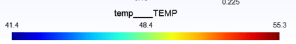
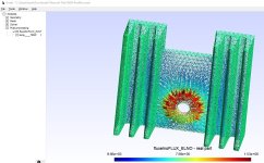
1) [Simulation color] For each picture, there is the legend showing which color is which temperature (extract attached). That's how i got the temperature value in the table
2) [Actual Comparison Temperature] No, i have not made this because i can't, as i haven't purchased the 3U-300mm chassis and would like to guess if it would work.
I know 6L6 config with transistors on the left is working, because he was showing it, without mentionning thermal issue.
= no being able to do measurement is why i went to simulation
3) What i have done as measurement=using my M2x inner/outer temperature to have a guess at possible inner/outer temp for the simulation (yet, this is a rough approximation because my M2x is 4U-400mm and each transistor might work differently than Theseus).
If i wanted a better reference than 6L6 Theseus, i would need to:
a. know the power dissipation of M2X transistors
b. model and calculate a 4U-400mm heatsink
Maybe i will do that in the futur.
(Aleph simulation are rough as well, deduced from standard Aleph and a user (Randshow) who has a 3U-300mm but mentions it is running very hot.)
4) [Copper Spreader]
a. Thanks, that's a good idea (which i could later simulate easily once i find the right part and have its dimension)
b. I was thinking of somehow adding others HS on the inner side (not ideal but with some openning in the top panel...could help = everything to avoid going over 120mm or putting a fan)
c. Also i wouldn't want to go to 400mm because i would like to keep the Theseus size "contained". (and it cost more to have more panels drilling per UMS specs)
Attachments
Last edited:
Ta, I missed the simulation legend at the bottom.
It's likely that some copper bar would make a reasonable improvement in transferring heat out to where the main heatsink is sort of idling at near ambient temp.
Do you know what insulation voltage is needed for each FET, and do the FET drains need to be isolated from each other? Spreaders are great if you can get a sheet of insulation to suit mounting the bar to the heatsink. Mounting the FETs direct to flat copper with some paste gives the lowest Rth (apart from soldering to the copper), which is a key attribute. Your simulation may be able to indicate the nett benefit - which may or may not entice going down this road.
Hi
Thanks for the different advices & questions...
I plan to use Keratherm sheet between transistor and heatsink, but the reference is already using it (according to the picture).
As for "Do you know what insulation voltage is needed for each FET, and do the FET drains need to be isolated from each other?", i don't know what are insulation voltage! But that's an opportunity to learn.
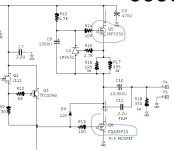
Schematic of the board is attached, as well as the data sheet of each transistor.
Looking quickly i have not found "insulation voltage" in the spec, but i am not very knowledgeable with electronic mosfets.
Same regards FET drains isolation.
Regards
Thanks for the different advices & questions...
I plan to use Keratherm sheet between transistor and heatsink, but the reference is already using it (according to the picture).
As for "Do you know what insulation voltage is needed for each FET, and do the FET drains need to be isolated from each other?", i don't know what are insulation voltage! But that's an opportunity to learn.
Schematic of the board is attached, as well as the data sheet of each transistor.
Looking quickly i have not found "insulation voltage" in the spec, but i am not very knowledgeable with electronic mosfets.
Same regards FET drains isolation.
Regards
Attachments
The supply voltage is what you need to handle, not the specification of the FET - the insulation only has to deal with the voltage in the circuit. And the two drains definitely have to be isolated from each other or you'll short out the power supply since one is connected to each rail.
Generally we always isolate devices from a large heatsink to preclude any chance of shorting out the amp circuitry by the heatsink touching something else. Often the heatsink is electrically part of the chassis.
Generally we always isolate devices from a large heatsink to preclude any chance of shorting out the amp circuitry by the heatsink touching something else. Often the heatsink is electrically part of the chassis.
Then, yes, per the circuit schematics, the drains are not connected to each other.
I will always insulate any wire (if i choose to use wire for mosfet & PCB connection to spread the mosfet farther away than permitted by the PCB) so they only connect to what they are supposed to connect to.
I will always insulate any wire (if i choose to use wire for mosfet & PCB connection to spread the mosfet farther away than permitted by the PCB) so they only connect to what they are supposed to connect to.
The IRFP250 is nice in that it has a plastic body and mounting hole, making it easier to mount, and maintain insulation from the FET metal base to the heatsink when a thermal insulator pad is used. Mounting the FET to a heat spreader, using no isolation pad, makes for better thermal conduction, but electrically isolating the heat spreader from the heatsink may be the harder path for you to take.
I would use electrical isolation for the lower FET, even though the FET drain is at ground, to avoid ground loop risk.
The main benefit of this discussion is to reduce FET junction temperature rise above ambient. I assume this is a concern for you?
I would use electrical isolation for the lower FET, even though the FET drain is at ground, to avoid ground loop risk.
The main benefit of this discussion is to reduce FET junction temperature rise above ambient. I assume this is a concern for you?
It was discussed originally in another thread, linked in the 1st post: most build of the Ship of Theseus were with 4U 300mm heatsink. Due to space constraints on my side, i wanted to see if a 3U 300mm could be Ok.
One amp with 4U 300mm had the mosfets put mostly on 1 side (Reference Theseus 6L6) it was ok apparently (heatsink not fully used i could say)
So the idea was to check if by better spreading the heat with a placement more centered, i could make do with a 3U 300mm
One amp with 4U 300mm had the mosfets put mostly on 1 side (Reference Theseus 6L6) it was ok apparently (heatsink not fully used i could say)
So the idea was to check if by better spreading the heat with a placement more centered, i could make do with a 3U 300mm
Far from an expert on the matter, but some thoughts regarding real world issues-
1) All I care about is junction temperature, so coupling to the heatsink is critical. I don't want a deceptively cool heatsink and high junction temperature. If the sink is warmer and the junction cooler, so much the better.
2) How flat can you get the heatsink? It matters and I machine the mounting surface for critical stuff. As-extruded isn't good enough.
3) I wish somebody with the right setup would measure every known insulator under the exact same conditions and publish the results in the same format/units. Are the expensive high end silicone pads really better than all else? All thermal insulators other than beryllium ceramics are BAD- it's only by minimal thickness that they look good. Ditto all thermal compounds- use as little as possible to fill the gap. I like the phase change materials because they go to near zero thickness on heating, but they're expensive for what they are (loaded wax?) I bet you could DIY a good one.
4) As above, copper spreaders are the bomb if properly designed. Copper is great, but this is high end audio- silver is better!
5) Watch capacitance. I once had to use thick alumina insulators not because of voltage, but to maintain minimal capacitance for stability.
6) Maximize convection. The flow may be more restricted or local than you think. The whole package needs to be simulated, not just the heatsink in space.
7) IR measurements are great- but only if you paint everything with a thin layer of flat black paint! Emissivity has to be known for the result to be meaningful. I make a lot of IR measurements at work and will often put a small circle of flat black in critical areas. Do that and you'll be within a degree or two between IR and thermocouple. Hint- you can wire thermocouples back-to-back and do differential measurements.
Great thread!
1) Agreed.
2) I am not that far as to grind the heatsink to smooth it. Yet, it doesn't cost anything...
3) Insulator: personnaly, i am OK trusting the specs of the manufacturer.
Doing more would require time & money i don't have. Even commercial companies would start with those assumptions 1st, may confirm later if a problem arise or if the volume bought justify the testing.
4)
Aluminium thermal conductivity is around 237 w/(m²K)
Copper 398w/(m²K)
Silver 407w/(m²K)
I think silver is more/much more expensive than copper, so the thermal vs cost benefit isn't there. (i might be wronged by the price in different units...)
5) Ok
6) Yes, but i also don't want to add a fan!
Having a 3U heatsink is the allow some free air movement on top. (I have a 4U amp which i choose to move out because limited airflow was detrimental)
Modelling the whole thing with airflow may be possible with the soft i have, yet it is a very different endeavour and i was quite happy with the advice on h=15 for external convection.
Moreover, before that, it would be better to take into account the radiation: i am currently not, should change the simulation or even the software to do that.
7) I don't want to bother people at work for IR measurements, although...done at the right time, it might only cost a few pastries😉
I could ask on the other forums what the temperature on top of the heatsink for the 4U "left side" config and "centered" config and/or model my M2X and make measurements on it
So update about this topic will now be far and between since different options would take time.
Anyways, heatsink purchase is not for now.
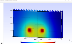
Small(ish) update: moving 1 of the mosfet to the right on the "roughly centered" 3U-300mm config lead to a max temperature similar to 6L6 reference (-0.1°C @tmax). So, it should be OK if i wire the mosfet to have the freedom to put them where i need (instead of following the pcb localization)
Setup | Tmax | Tmin | Tmax Vertical (High) | Tmax Vertical (Low) |
Reference Theseus 4U (6L6) | 55.3 | 41.4 | 47.9 | 51.4 |
Theseus 3U Mosfets Optimized 1 | 55.2 | 47.3 | 50 | 51.3 |
Attachments
Hi.
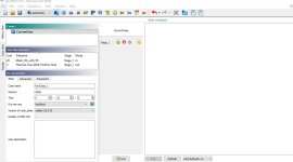
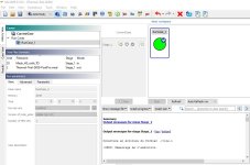
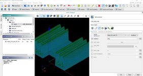
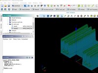
If some are interested to play with simulation, 1st with a trial on a simple case, to see if the tools are working... (i would later post the "Modushop" type of heats ink calculation i did... as archival)
1. Preprocessing, Solver integration, Post-Processing was Salome-Meca, with Code-Aster solver integrated https://code-aster.org/spip.php?article303
2. Windows version (that one used), recently updated https://code-aster-windows.com/download/ [i am updating everything to 2023]
a. download and install Code Aster (will put it in the right location)
b. download and install Salome (should recognize where the solver, Aster, is)
3. Another post-processor, lightweight: https://gmsh.info/
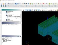
4. Example/Tutorial is "Thermal-Trial-SK09.hdf"
"Mesh-Only" inside can be openned with Salome mesh module or GMSH "Mesh_HS_with_TO"
"PostProcessing Only" can also be openned "Thermal-Trial-SK09-PostPro"
But with the *.hdf openned in Salome-Meca, you should have everything
5. Go to Salome "AsterStudy", "History", click "current case" and then "run" in the bottom middle
6. A few pictures are given. This is just to see if things work, physics on this case is not checked (heat is going through the hole wall...not the possible location of the mosfets).
To play, hot temperature of 150 degrees can be modified in "BC and LOAD"-> "loadst", cold temperature around and exchange coef in "BC and LOAD"->loadst2
I am not expert in the domain (later cases were done differently for the model and conditions), it is just if some would like to discover this a bit and "play" with it
If some are interested to play with simulation, 1st with a trial on a simple case, to see if the tools are working... (i would later post the "Modushop" type of heats ink calculation i did... as archival)
1. Preprocessing, Solver integration, Post-Processing was Salome-Meca, with Code-Aster solver integrated https://code-aster.org/spip.php?article303
2. Windows version (that one used), recently updated https://code-aster-windows.com/download/ [i am updating everything to 2023]
a. download and install Code Aster (will put it in the right location)
b. download and install Salome (should recognize where the solver, Aster, is)
3. Another post-processor, lightweight: https://gmsh.info/
4. Example/Tutorial is "Thermal-Trial-SK09.hdf"
"Mesh-Only" inside can be openned with Salome mesh module or GMSH "Mesh_HS_with_TO"
"PostProcessing Only" can also be openned "Thermal-Trial-SK09-PostPro"
But with the *.hdf openned in Salome-Meca, you should have everything
5. Go to Salome "AsterStudy", "History", click "current case" and then "run" in the bottom middle
6. A few pictures are given. This is just to see if things work, physics on this case is not checked (heat is going through the hole wall...not the possible location of the mosfets).
To play, hot temperature of 150 degrees can be modified in "BC and LOAD"-> "loadst", cold temperature around and exchange coef in "BC and LOAD"->loadst2
I am not expert in the domain (later cases were done differently for the model and conditions), it is just if some would like to discover this a bit and "play" with it
Attachments
-
Mesh_HS_with_TO.zip1.7 MB · Views: 76
-
Thermal-Trial-SK09-PostPro.zip8.9 MB · Views: 71
-
 Salome-1.jpg75.4 KB · Views: 74
 -
 Salome-2.jpg93.6 KB · Views: 80
 -
 Gmsh-1.jpg206.3 KB · Views: 70
 -
 Gmsh-2.jpg226.6 KB · Views: 76
 -
 Salome-3.jpg196.5 KB · Views: 71
 -
 Salome-4.jpg125 KB · Views: 72
 -
 Salome-5.jpg136 KB · Views: 70
 -
Thermal-Trial-SK09.zip2.1 MB · Views: 59
- Home
- Design & Build
- Parts
- Heat Sink & Thermal dissipation, some calculations if interesting to some