Building the F5 Turbo v2
This is the "in-progress" thread for the official build guide of the F5Turbo. This is not the final guide.
I am building a V2, with 2 outputs per side, source diodes, and no cascode. DIYaudio store PCB are being used and it will all go into a 5U 400mm "BIG Amp Chassis"
The Firstwatt F5 Turbo article from Nelson Pass, in case you haven't seen it - www.firstwatt.com/pdf/art_f5_turbo.pdf
Anyway, on to the build. 🙂

The Chassis in the shipping box and the PCB.
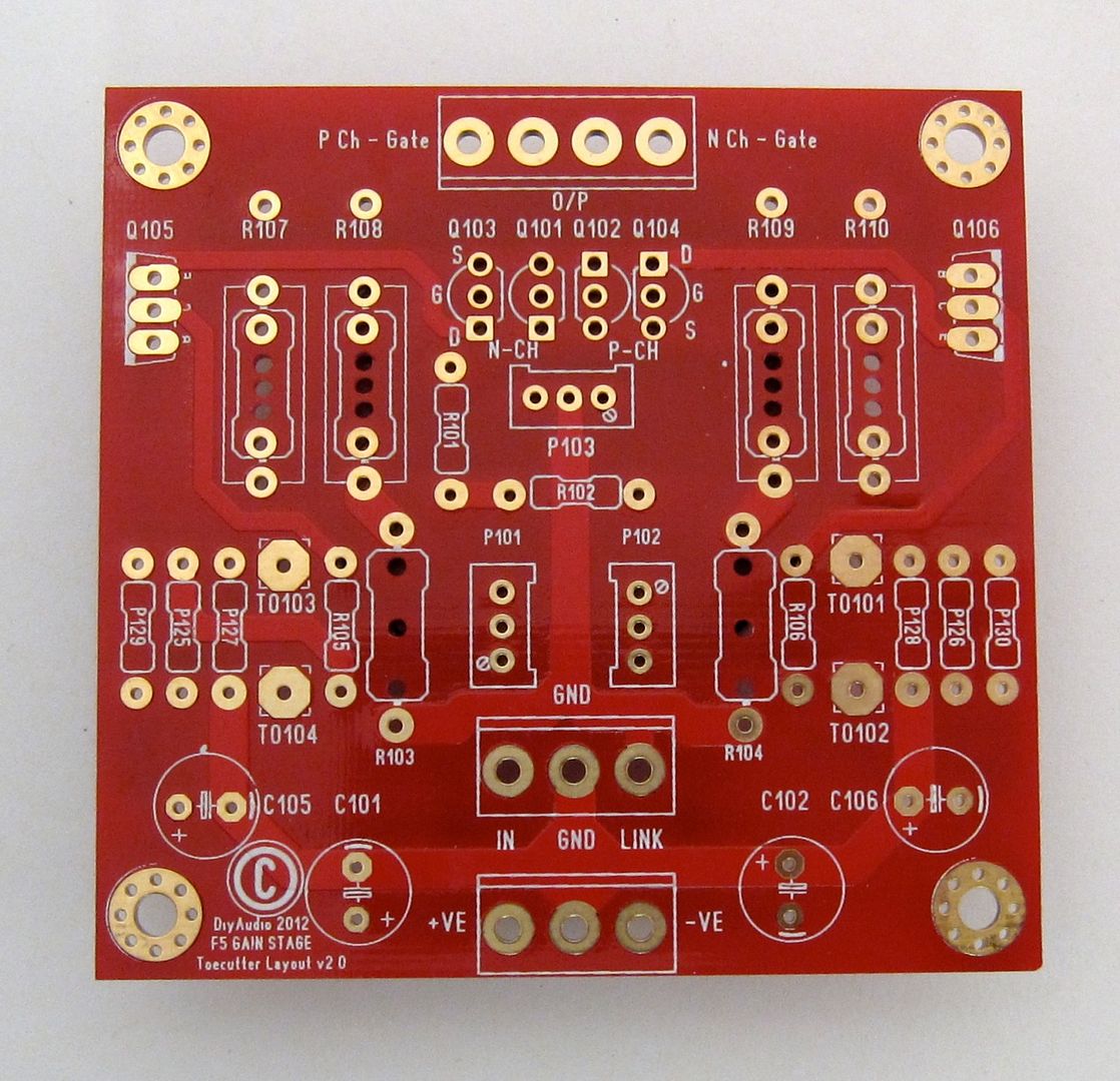
While we are at it, here is a good photo of the Front-end board
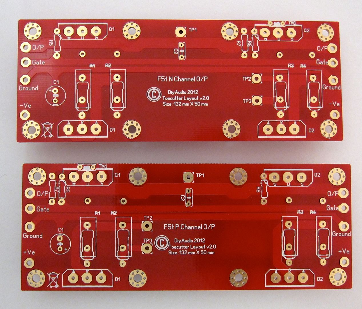
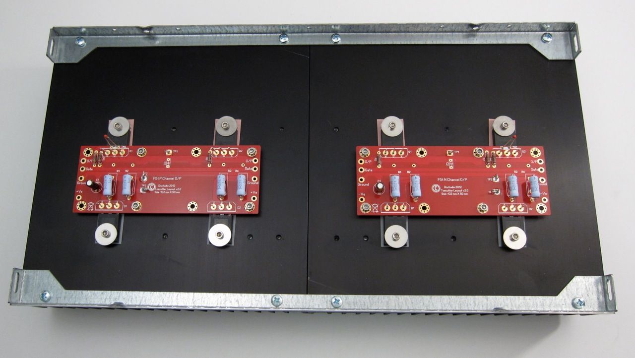
And here are the output boards. The component numbering on all these boards don't quite match up with the schematic, that will need to be clarified in the guide. In the time being, a bit of logic and inspection will let you figure it out.
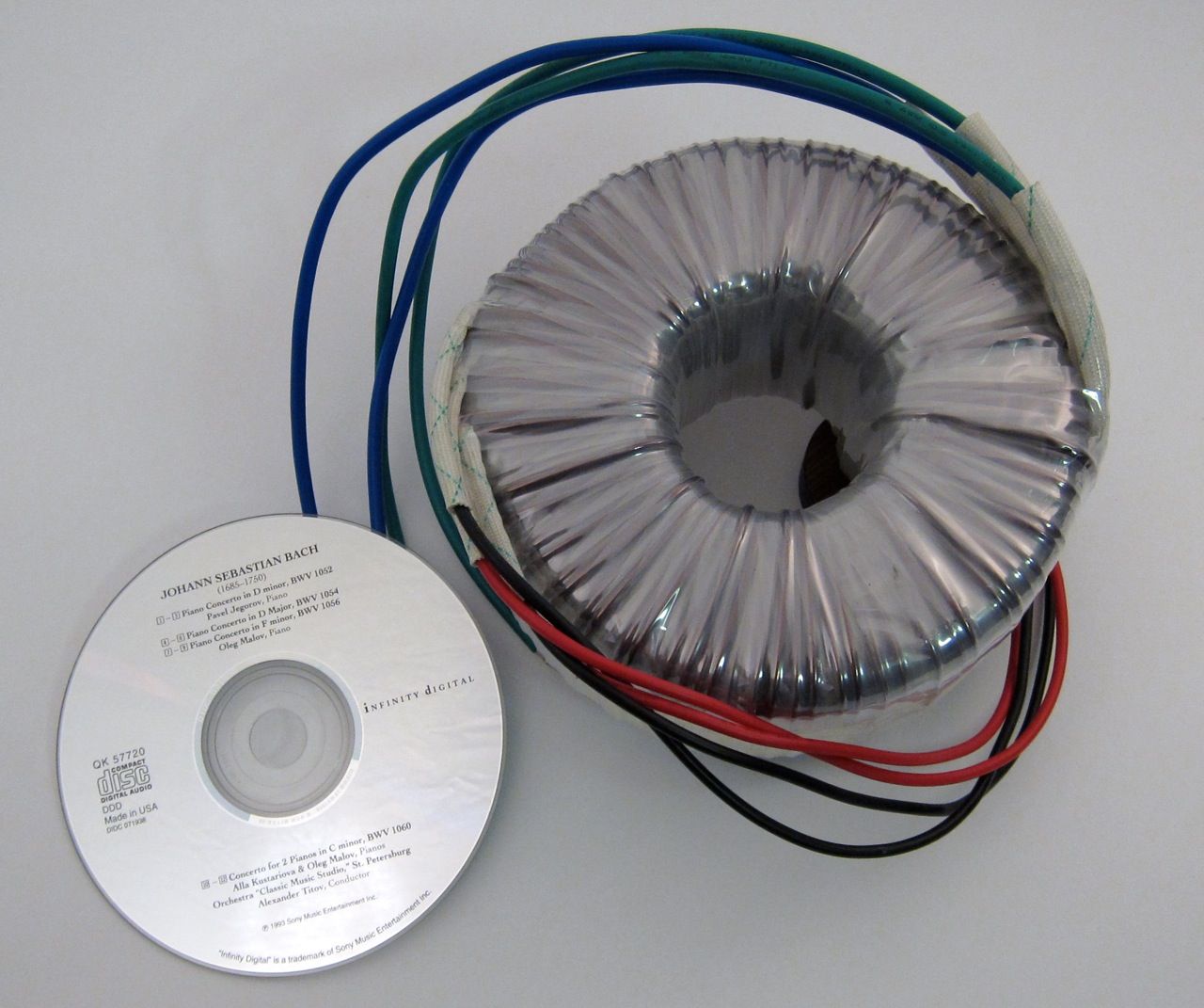
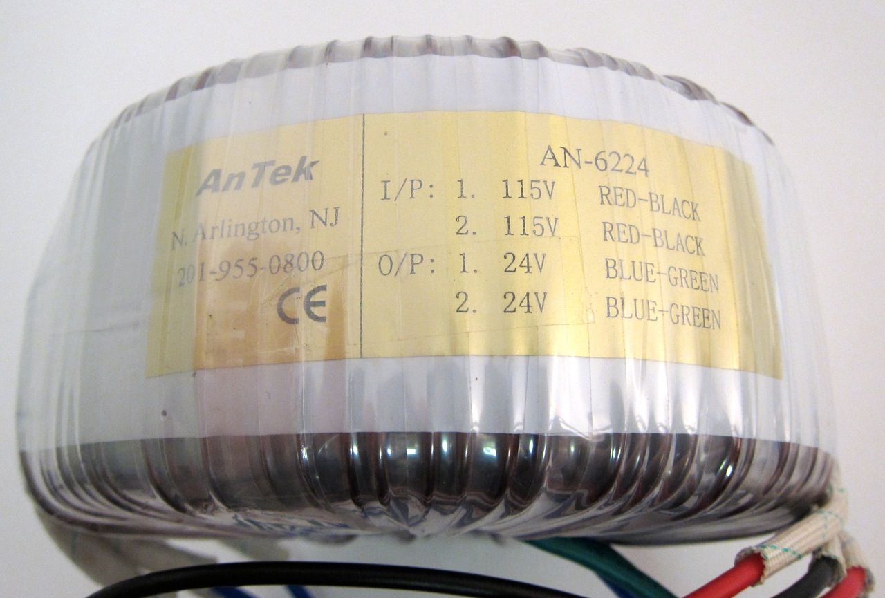
A large transformer. 🙂
Building the PSU -
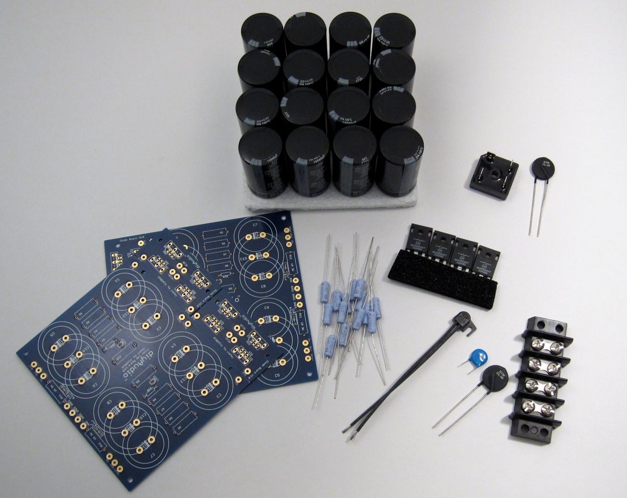
Components - PCB, Caps, resistors, thermal shutoff, inrush limiter, line cap, ground loop breaker, rectifier diodes. Not shown are rail LEDs, bleeder resistors.
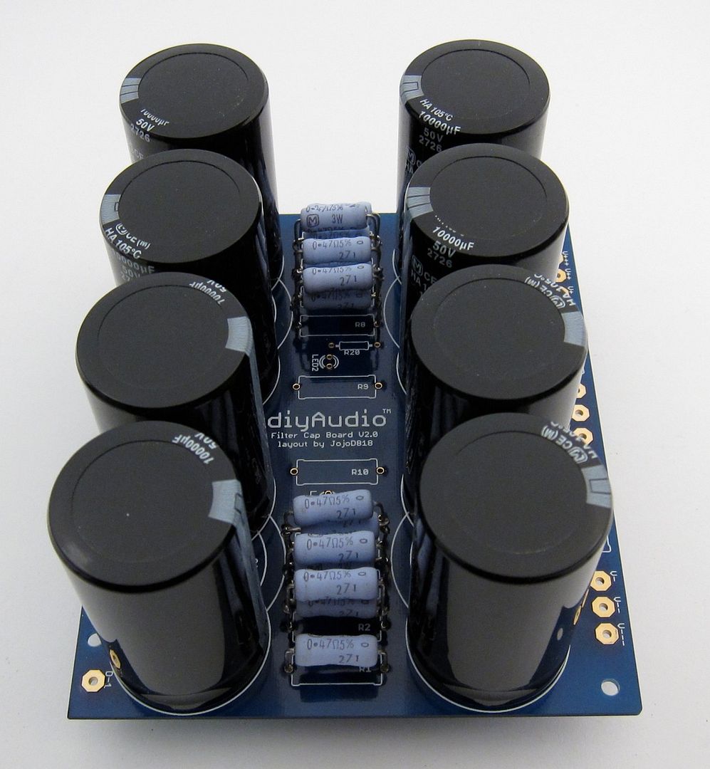
Why 2 PCB? to hold the (16) 10,000uf 50v capacitors. 🙂
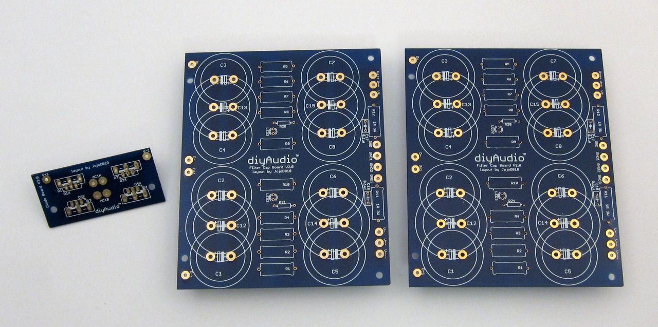
We will only need one Bridge PCB, and the rest can be cut off the boards.
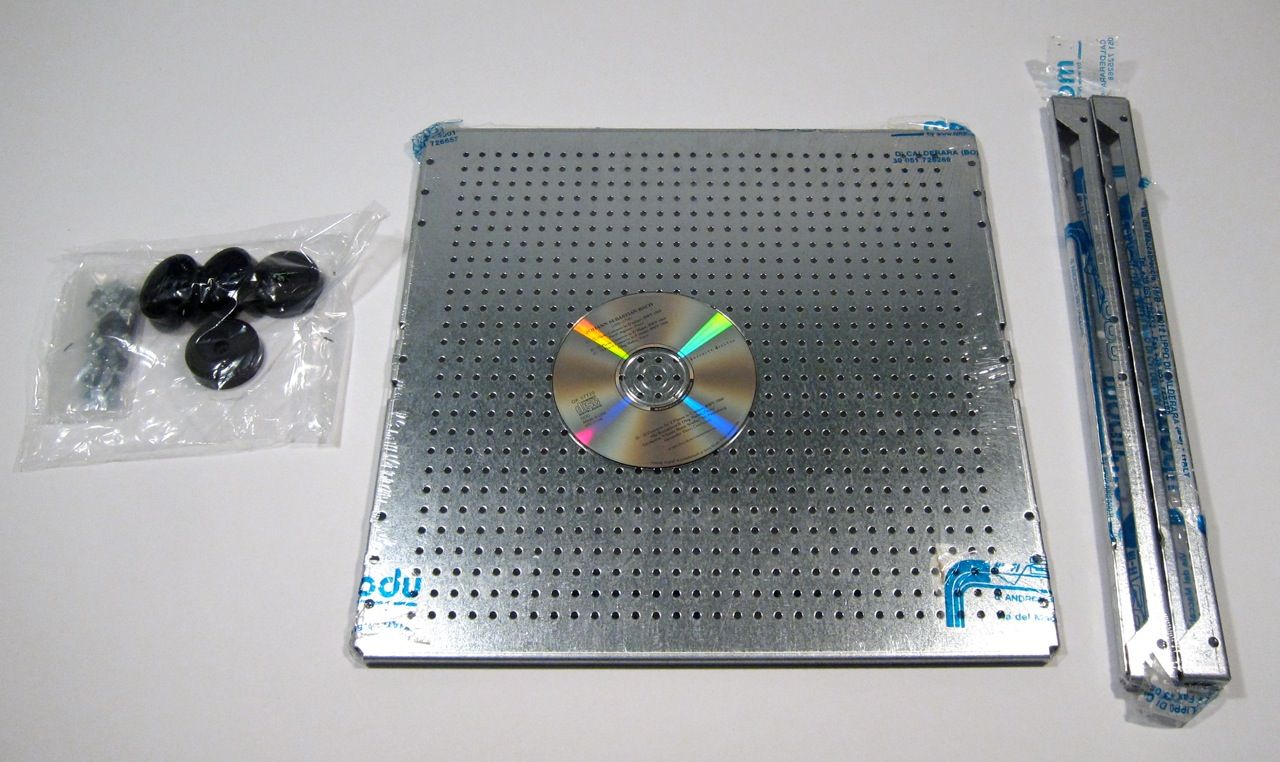
The PSU will be built on the 'DIY friendly' baseplate, shown here with some of the chassis hardware.
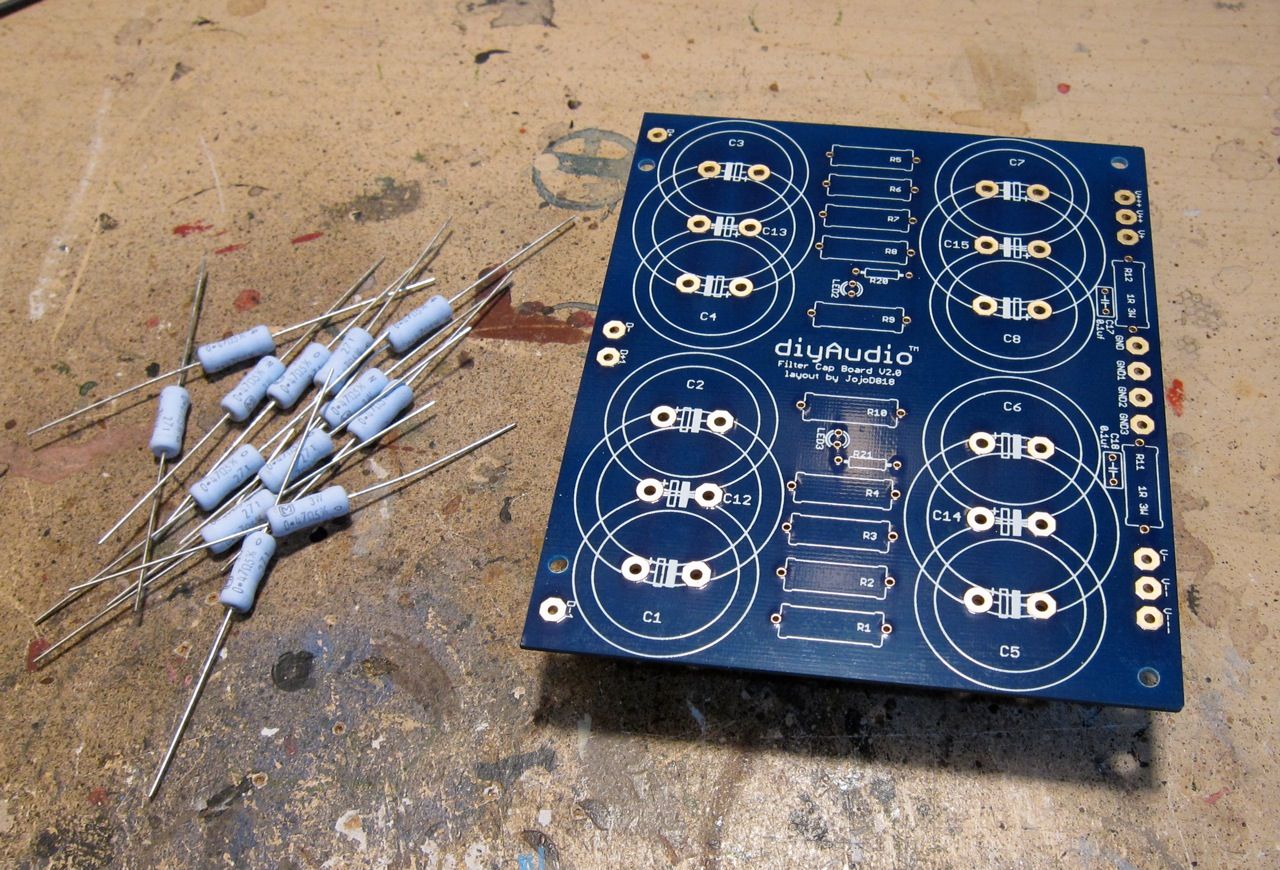
The first PCB will hold only caps and the filter resistors. But there is only room for eight, and the board holds fourteen…
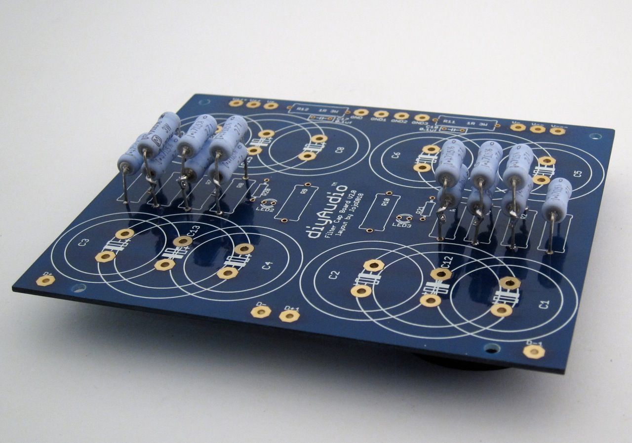
So a bit of stacking is required.
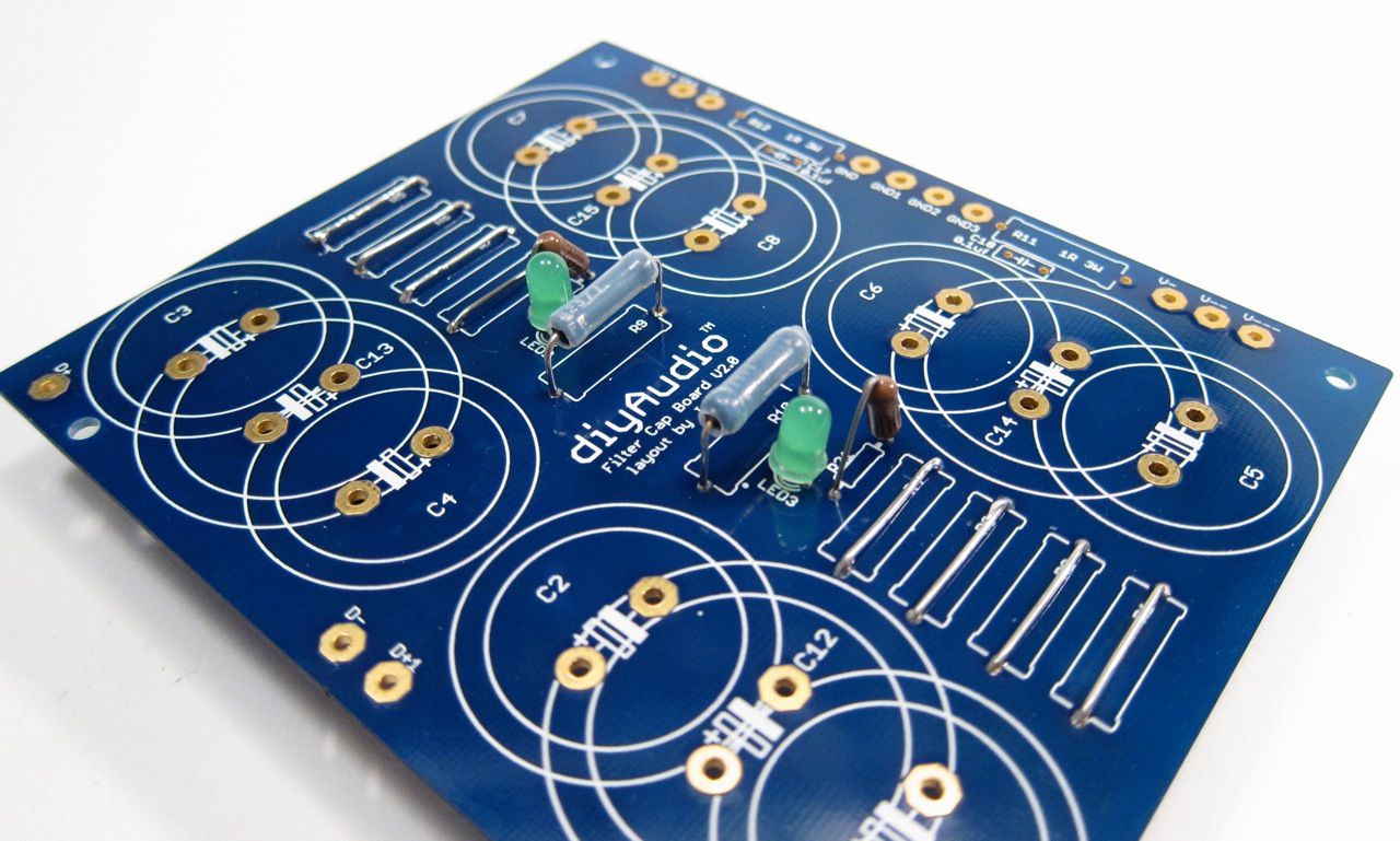
The other board will have the LEDs and bleeders. Please note that the resistor pads must be jumpered.
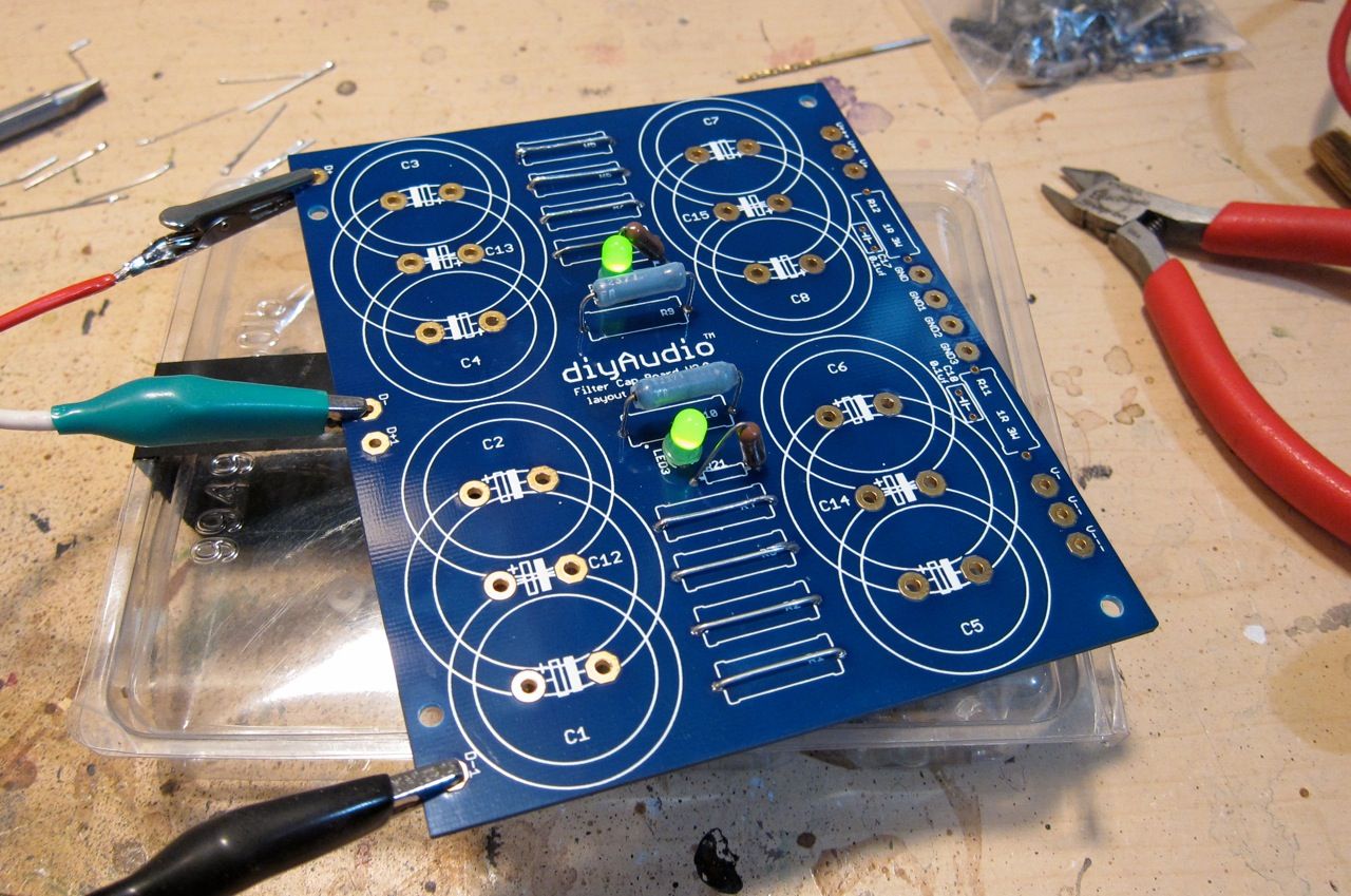
Testing the LEDs with a bench PSU
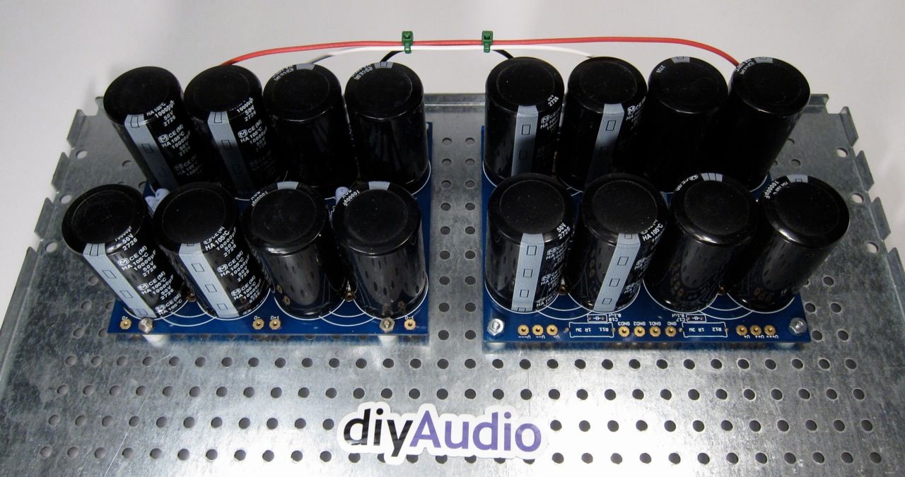
The 2 PCB now stuffed. The left will have the input from the rectifier, the right will be the output to the amp.
The other side of the PCBs
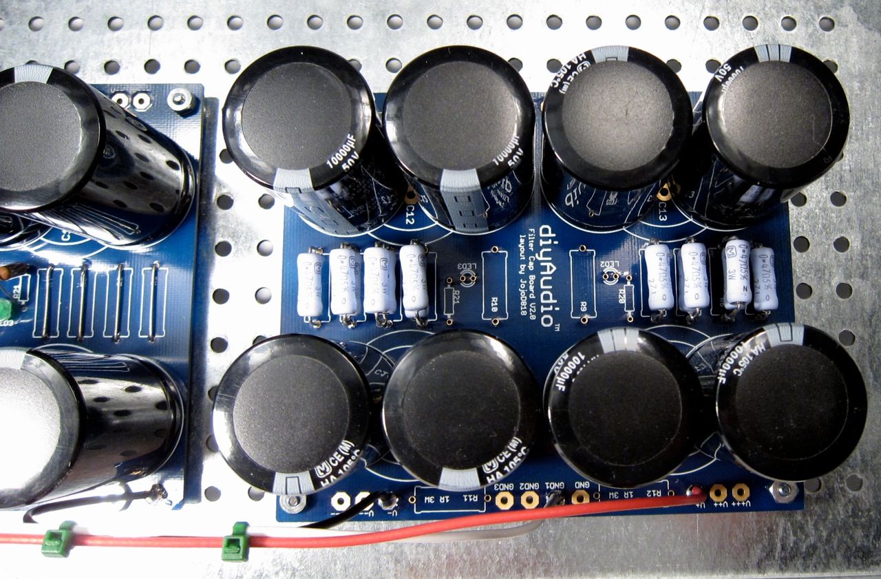
Looking down at the first PCB
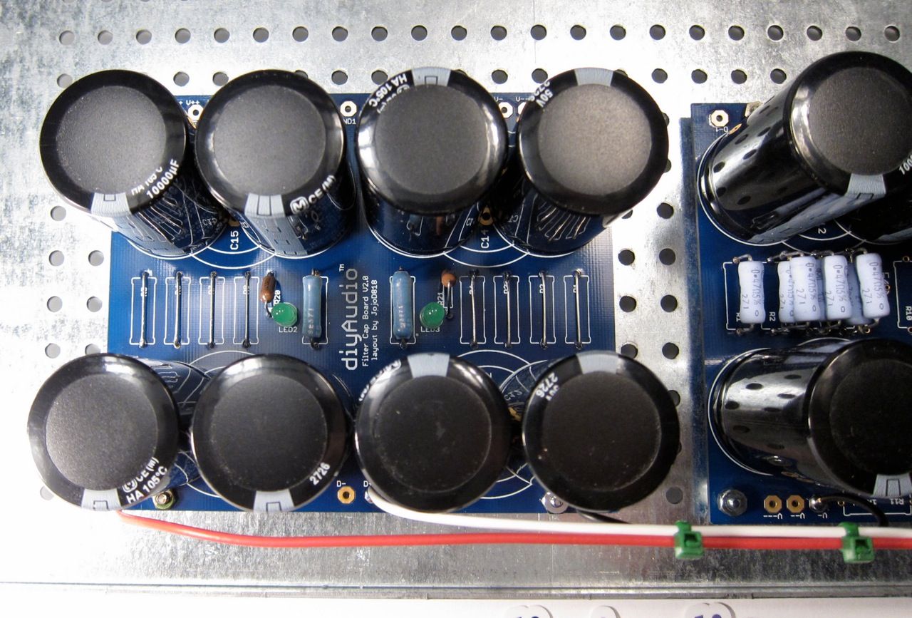
Looking at the second. Again, please note the jumpers where there are the resistors.
This is the "in-progress" thread for the official build guide of the F5Turbo. This is not the final guide.
I am building a V2, with 2 outputs per side, source diodes, and no cascode. DIYaudio store PCB are being used and it will all go into a 5U 400mm "BIG Amp Chassis"
The Firstwatt F5 Turbo article from Nelson Pass, in case you haven't seen it - www.firstwatt.com/pdf/art_f5_turbo.pdf
Anyway, on to the build. 🙂
The Chassis in the shipping box and the PCB.
While we are at it, here is a good photo of the Front-end board
And here are the output boards. The component numbering on all these boards don't quite match up with the schematic, that will need to be clarified in the guide. In the time being, a bit of logic and inspection will let you figure it out.
A large transformer. 🙂
Building the PSU -
Components - PCB, Caps, resistors, thermal shutoff, inrush limiter, line cap, ground loop breaker, rectifier diodes. Not shown are rail LEDs, bleeder resistors.
Why 2 PCB? to hold the (16) 10,000uf 50v capacitors. 🙂
We will only need one Bridge PCB, and the rest can be cut off the boards.
The PSU will be built on the 'DIY friendly' baseplate, shown here with some of the chassis hardware.
The first PCB will hold only caps and the filter resistors. But there is only room for eight, and the board holds fourteen…
So a bit of stacking is required.
The other board will have the LEDs and bleeders. Please note that the resistor pads must be jumpered.
Testing the LEDs with a bench PSU
The 2 PCB now stuffed. The left will have the input from the rectifier, the right will be the output to the amp.
The other side of the PCBs
Looking down at the first PCB
Looking at the second. Again, please note the jumpers where there are the resistors.
Last edited:
Wait , what ..!
Another baby , Whats with all the dinky toy 2 pr output builds 🙄
outputs aren't that expensive , c'mon guys , Do a 4 pr, its a turbo for bleeezus sakes , why not make some power !!!
🙂
Another baby , Whats with all the dinky toy 2 pr output builds 🙄
outputs aren't that expensive , c'mon guys , Do a 4 pr, its a turbo for bleeezus sakes , why not make some power !!!
🙂
Last edited:
Why? Three reasons -- Heatsink, heatsink and heatsink.
A 2pr stereo is about all the 5U can handle. 🙂
A 2pr stereo is about all the 5U can handle. 🙂
Yay! Another 6L6 build log! Looking forward to seeing the progress. I'm still very happy with my F5... and afraid of building a turbo for fear of not wanting the original anymore! Besides, I don't think I need the extra power or electricity bill increases. I have the Aleph Xs for that. 😛
Why? Three reasons -- Heatsink, heatsink and heatsink.
A 2pr stereo is about all the 5U can handle. 🙂
Only if you increase the amt of class-a bias ....
6L6,
looks great, as usual.
I am interested to see how that bottom takes the weight of the toroid. I have a suspician you might have some give.
Wayne,
my V3 is at home on sinks. Just didt get the PSU's finished.
looks great, as usual.
I am interested to see how that bottom takes the weight of the toroid. I have a suspician you might have some give.
Wayne,
my V3 is at home on sinks. Just didt get the PSU's finished.
.......
I am interested to see how that bottom takes the weight of the toroid. ......
just fine - if screwed properly to side brackets
6L6 - be sure , later , to (edit) include link in first post in thread - directly to powering up/biasing procedure ..... which you are going to write , in detail
good for us greenhorns ...... and handy , for later
🙂
Pots definitely need turning down if you have high Idss Jfets. If not, and amp is powered up, the fets are biased too high with pots set as they are from the vendor.
Looking forward to another 6L6 build.!
If the 5u heatsinks cannot take 4, what would you need to use to build the V2 from the schematic?
Why? Three reasons -- Heatsink, heatsink and heatsink.
A 2pr stereo is about all the 5U can handle. 🙂
If the 5u heatsinks cannot take 4, what would you need to use to build the V2 from the schematic?
If the 5u heatsinks cannot take 4, what would you need to use to build the V2 from the schematic?
This case (5U 400mm)
Something is getting lost in translation as I haven't gotten to those photos yet... This is going to have the V2 from the schematic, with 2 output pairs and diodes.
This is a photo of one channel output boards on the heatsinks, the Front-End board will be mounted on the baseplate.
I will continue the guide shortly.
6L6 - be sure , later , to (edit) include link in first post in thread - directly to powering up/biasing procedure ..... which you are going to write , in detail
Yes, that info, as well as much more procedure in general will all be in the official guide. This thread is just the teaser.
Buzz, can you please point to the thread/post where 2nd and 3d harmonics adjustment with P3 described? Can't find it :-(
6L6 , where did you buy this heat sink chassis from ?
I think from DIY Audio Store
5U Amplifier Chassis w/ Aluminum Heatsinks and Faceplate - Full width with 40mm Heatsinks - Chassis
Didiet
6L6: how did you configure the first PSU board with the filter resistors so that all 8 caps are connected BEFORE the resistors (and not 2 caps before the resistors and 2 caps after them per rail)?
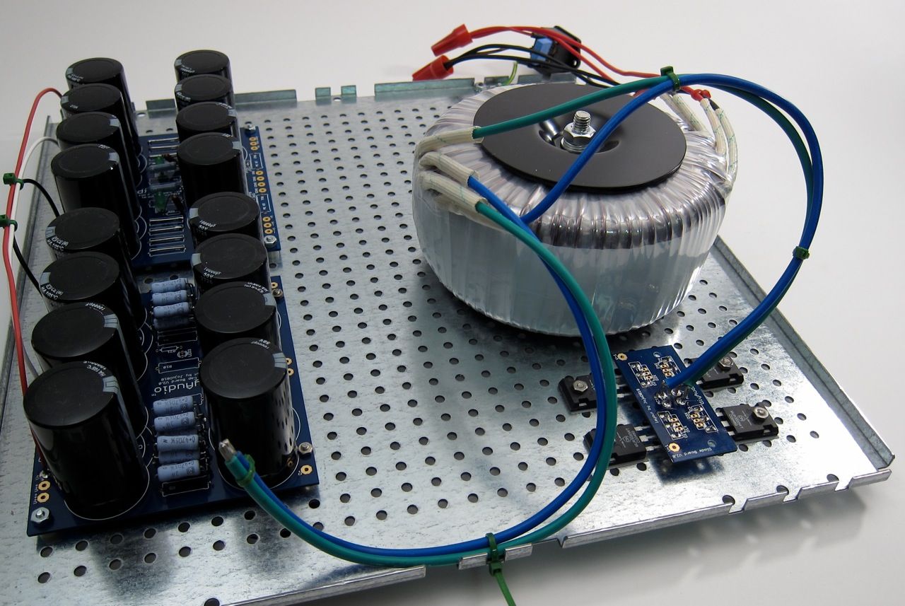
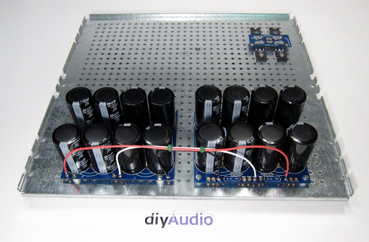
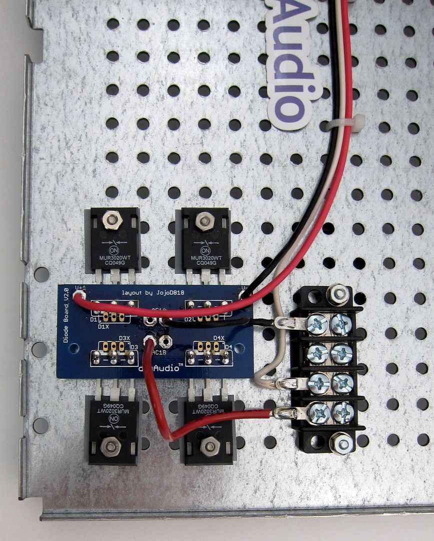
At this point it becomes necessary to power things up in stages to verify that the PSU is working properly. Here you can see a temporary AC hookup on the far end, and the secondaries connected to the rectifier, and a centertap made from the inside wires. There should be +35v between the V+ pad on the bridge board and the centertap, -35v between V- and the centertap.
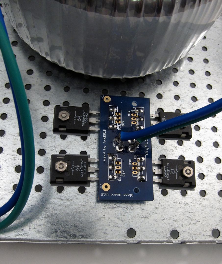
Don't forget that the bottoms of the diodes are conductive, so you must use an insulator. These particular silpads are made for this case, and insulate well, but are small and require care when mounting to make sure they are in the right spot.
Anyway, if the bridge tests properly, then connect it to the capacitor boards. It's a good idea to use a light bulb mains lead for this.
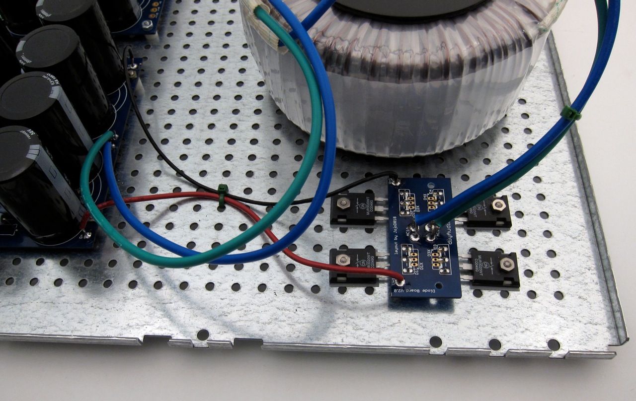
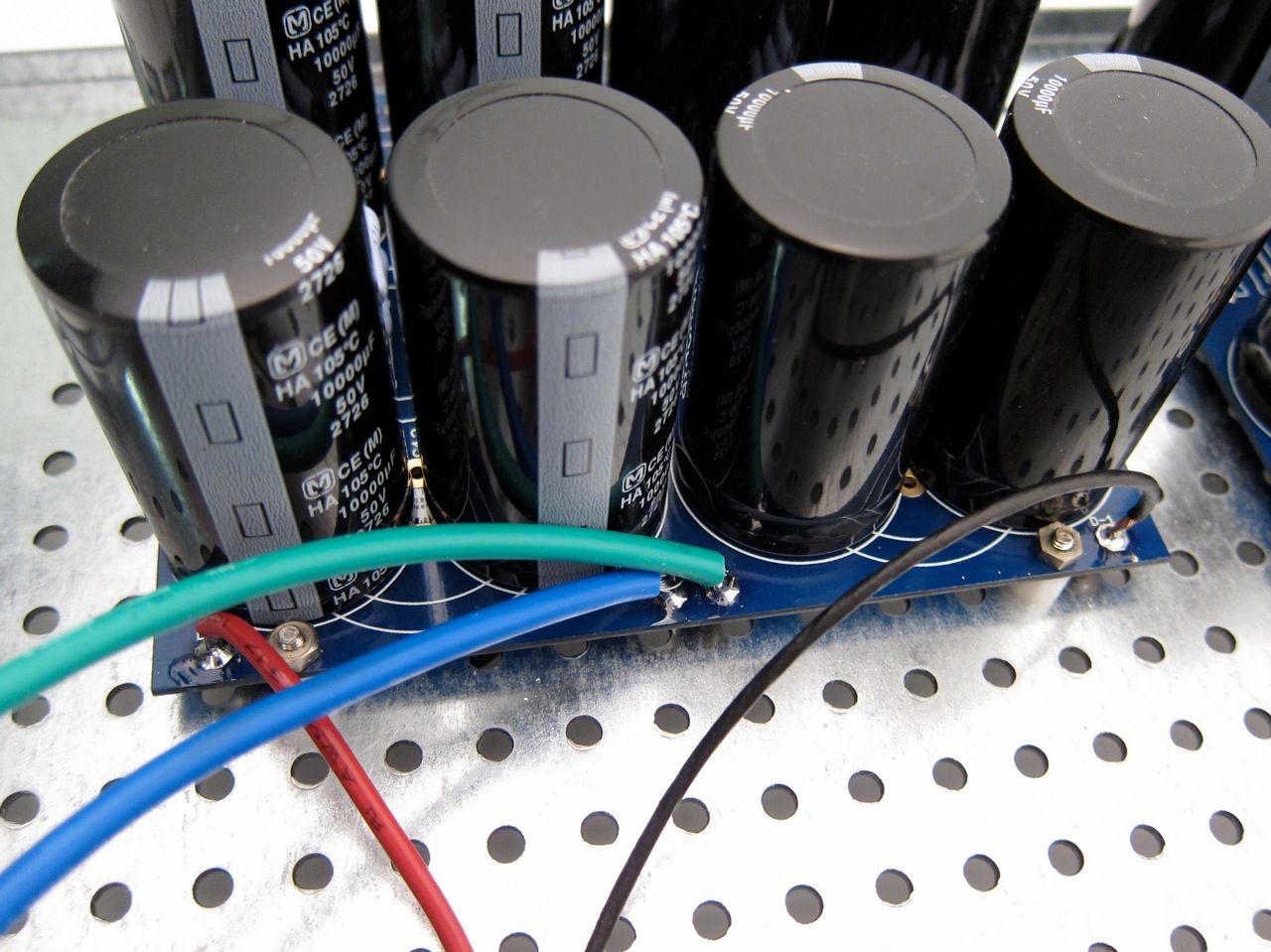
(This is temporary wiring)
Check the voltages at the far side of the PCB, check the LEDs for proper operation.
As the build progressed I needed to adjust the position of the bridge, and I added a terminal block for the transformer secondaries. (I am likely going to use this chassis for more than one guide, and keeping the transformer easily interchangeable will be useful.)
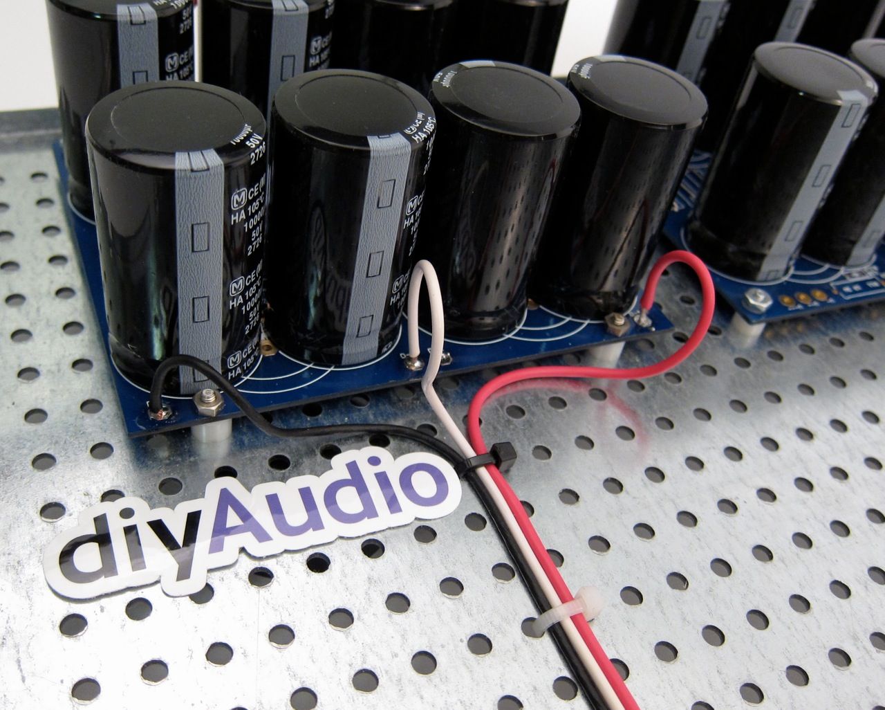
Wiring from Bridge to PCB
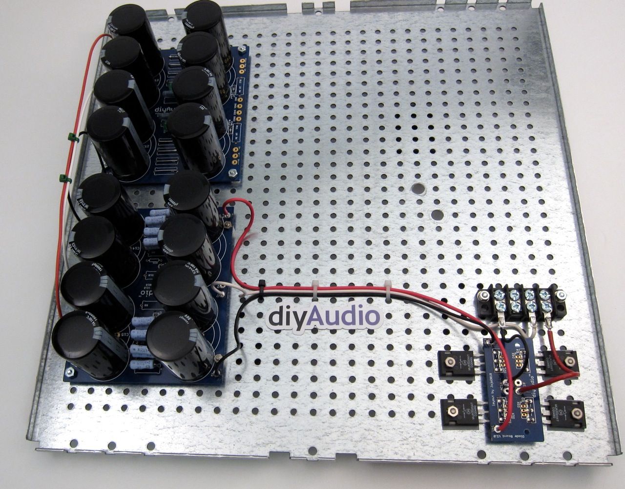
The completed DC section of the PSU
Last edited:

6L6,
looks great, as usual.
I am interested to see how that bottom takes the weight of the toroid. I have a suspician you might have some give.
Wayne,
my V3 is at home on sinks. Just didt get the PSU's finished.
Actually, its not bad at all. Just got my 5U Deluxe case put together. The way the two pans go together stiffens it considerably.
Russellc
- Home
- Amplifiers
- Pass Labs
- Building an F5 Turbo v2 (in-Progress)