F5 Turbo V2 TH1 and TH2 with or without?
hi guys this is the first time I draw this PCB I have a question the TH1 and TH2 they go on the Q3 and Q5 do they need glue or just thermal compound or does not need any at all? oh note the power semiconductors are there only for illustration purpose
hi guys this is the first time I draw this PCB I have a question the TH1 and TH2 they go on the Q3 and Q5 do they need glue or just thermal compound or does not need any at all? oh note the power semiconductors are there only for illustration purpose
Attachments
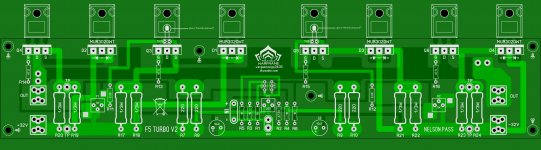
Glue is fine. They are there to make the bias circuit compensate with the increase in the mosfet tempature.
Glue is fine. They are there to make the bias circuit compensate with the increase in the mosfet tempature.
thank you I'm gonna continue on the PCB layout making sure that there are no bugs 🙂
good day
Regards
Juan
So after letting my partial V2 build set for a couple of years I'm back to getting it going. let me describe mine it is part V2 and V3 together. I'm using the cascode setup but not using the output diodes. I'm running ~35 volt rails. I have 2 output transistors per half for 4 total per/channel. I'm testing currently now on bench at 1.5 amp per transistor bias. the heatsinks have settled at 55c deg after 2hrs. Amp is stable w/ 2-4mv offset. It is always a question as to what level of bias you should use. It gets confusing bc people will discuss and you do not know whether they are talking about bias per single transistor or combined with two transistor. I'm assuming single transistor. One thing that is peculiar is that my PS was completely balanced during load test with resistor load but powering amp one side is a volt lower than other side. This might be bc I'm using IRFP250 and IRFP9240?? The bias is all the same though through each half no mismatch. Anyone have any idea on this? Does it matter? maybe asymmetrical clipping??
So just figured out my problem with PS. I'm using two boards with wires between the 2. I connected +/- but forgot to connect the midpoint from the first to the second board. Everything good now. Would like clarification on biasing though.
Hello F5 Turbo People! How are you doing!
Is it any good? Sounding clean? Can I have a solid 100W at 4R at 1%THD from this F5 Turbo V2?
Is it any good? Sounding clean? Can I have a solid 100W at 4R at 1%THD from this F5 Turbo V2?
What is the power transformer VA rating? (for Stereo) Thank you. Does the transformer get too hot after a couple hours running? Please let me know.A few shots of the bench -
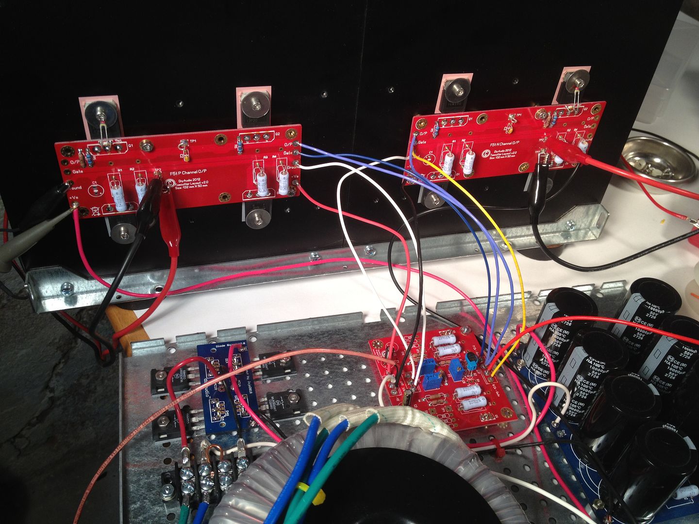
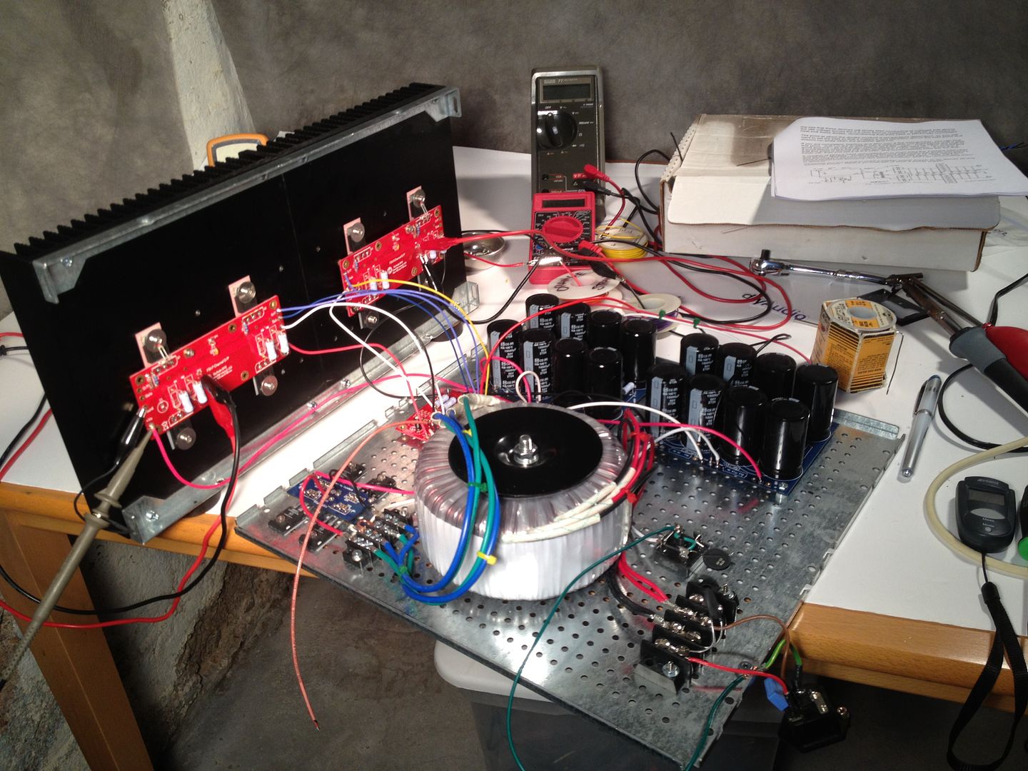
The Front-end board is mounted on the DIY-friendly base because it fits.
Yes, it looks like an explosion at a spaghetti factory - and this is only with one channel... Now I will be the first to mention that I haven't loomed anything together yet, and that will help a bit... but the penality of having the flexibility of the seperate FE board is all the extra wires. 🙂

- Home
- Amplifiers
- Pass Labs
- Building an F5 Turbo v2 (in-Progress)