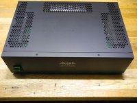
Musical Fidelity e300 power amp trannys help :(

hi folks,

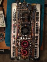
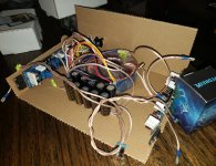
well ive got the above amp which i have repaired a few times. however i'ts now popped one of the o/p trannys, they are craftily labelled f15n/f15p. obviously these are mf's own codes, a habit they are fond of so they can rip you off when you need replacements.
there's a total of 4 per channel.
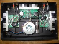
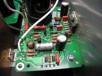
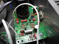
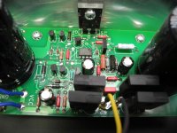
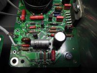
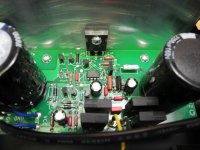
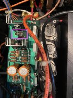
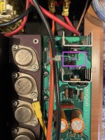
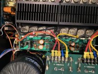
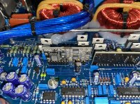
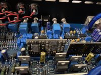
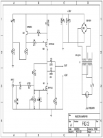
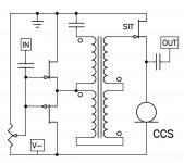
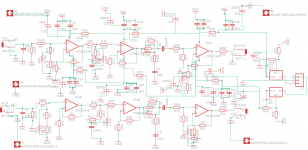
i've no idea if they are mosfet or bipolar. circuit consists of (input to output ) - 5534 and 5532 , then x2 of each mps a92/a42 (which ive changed a few times), followed by 2sd649/669 pair then the big TO3 f15n/f15p pairs. there is a bias pot too.
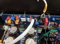
amp always sounded good but is terribly designed from an engineering point. originally had x4 50V 10000uf smoothing caps, running at , u guessed it, over 50v (53ish). changed them for 63v while ago.
i actually wrote to MF 1st time those caps dried out, pointing out the problem. Engineering director wrote back claiming the caps were rated at +10% so 55v . pah! the cheek of it.
also the mpsa92/42's literally cook, along with two 1/4 1k0 metal film resistors which should def have been 1/2 watt.
anyway, im flat broke at the minute and need to revive this beast.

if anyone can help with any info i'd be extremely grateful.

many thanks

raymond

Meridian 557 issue (see description/schematic)

I have a 557 Power Amp that is part of a Meridian stack I bought back in 1998 or so (502, 500, 566-24, 557). It's all performed flawlessly on a daily basis since last week when my 557 turned on then promptly turned itself back off. The soft start begins as usual and the system turns on (if there is a source you can hear audio from both channels) then after a couple of seconds, I hear a click, the system mutes and the power down process starts. I removed all inputs and outputs and tested again with the same results.

I was able to find a 557 schematic and as far as I can tell, there is a DC offset tripping the DC Protection Circuit you can see at the bottom of the attached schematic. I'm getting about 250mV of DC at the P.A. out line (at C2) coming down through R8 (at C3) to the minus input of the top op amp and the + input of the lower op amp (at C4) then on to R25 (labeled DC Protection). This is causing the op amps to drive the output transistor that mutes the amp and trips the protection relay shutting the amp off. I'm thinking that one of the main electrolytic caps is bad due to the age of the amp. Has anyone seen this problem with a 557 before?

Also, there is an adjustable resistor labeled R27, VA 1111 (probably Voltage Adjust?) at position B4 in the schematic. Does anyone know if that is the DC offset adjustment? See image and schematic below in reference to description. It's an impressive protection system. Any help will be greatly appreciated.

1907077-9b4d59b2-meridian-557-power-amplifier-upgraded-by-steve-huntleygreat-northern-sound.jpg

Meridian 557 Page 1.jpg

Thanks,

Dean

Valves for sale from Menorca

Hi, one year ago, I received a blast of four big lead batteries from my solar equipment, I lost both ears, not a at all but enough for not apreciate any more my equipments, as product of many years of get vaccum tubes for my projects, I got many of them. I have a old list I made several years ago, probably there are more, anyway I have list attached to this message you can check. If any of member make offers.
Best Regards
Esteban

LISTADO DE VALVULAS MIAS.xlsx - Google Drive

Also I have several tonearm, cartridges, turntables.

I uploaded a file with pictures from any other parts and components from my hifi chain. Loudspeakers, drivers, my record disc collection, with patienty is possible to see. More details are coming, today is hard day for me. I guess my way are headphones

Pictures: fotos hifi para vender - Google Drive

Arcam A75+ Distortion Issues

I'm mucking around a bit with an A75 that a buddy brought over. Physically everything looks perfectly great inside this amp. Nothing is burned, no zener diodes are amiss, all the lights do that they are supposed to, but this thing only makes about 2W into 8 ohms at 0.1%THD/1kHz. Oddly the performance of the amp gets better at low frequencies, and it just about does its rated power at 100Hz.

I have adjusted the bias to 15mV, temporarily tacked in new PSU caps, reflowed the solder joints on the output devices, and I split the pre/power sections and verified that the preamp section isn't causing problems. At this point it's both channels of the amplifier that both have the exact same problem. Other than some power supply parts, I'm not seeing a whole lot that's shared between channels. All the voltage checks listed in the service manual are OK and the 2W the amp puts out sound decent.

I'm trying to do as little work to the board as I possibly can since it's single sided and rather sensitive, so I'm hoping someone has experience with this particular issue.

Peerless 10" mid/woofer for two way?

Any thoughts on using the Peerless 830668 ten inch mid/woofer in a two way?
It seems to me that it could work well when used in conjunction with say an SB Acoustics ring dome TW29R which can be crossed quite low around 1500Hz .
It has very smooth roll-off with minimal break- up so also might suit a simple crossover.
It also suits a sealed box which for me makes it very appealing.Not a fan of ported bass.
https://www.google.com/url?sa=t&rct...er--264-1110&usg=AOvVaw3YZlMWzeBlAji-Lr9FV4UJ

EV Interface D/Sentry VI

Hi All,
I am in need of a crossover diagram for the Electro-Voice Interface D, or preferably the Sentry VI. I am doing a rebuild from a preexisting xo, but do not know the values on the coils. A link or a pic or anything would be appreciated. Lots of EV Int D manual links out there, but they all stop on PP 13 and the xo diagram is on a later page.
Thanks in advance,
B

"Shrine" SE Amp using 6AH6 and 1625

Some exchages with Tubelab have inspired me to build an SE amp similar to his Simple SE design, but using a 6AH6 pentode in triode mode at the input and a 1625 output tube (both extremely cheap and plentiful). I'm using the budget Edcor 5K single ended transformers at the outputs. The unit will be powered with an SMPS of my own design, providing power for both B+ and filaments. the whole shooting match will go in a 6" cube with the tubes poking out on top and the output iron and power supply inside. Finish will be black crackle, with a blue LED pilot light to complement the plate wires. Attached is a picture of the top deck. Next step is to power up the amp with a couple of bench supplies to look for screw-ups and check bias points. After that it's wring out the power supply (built and putting out voltage, but still needing a real going-over and EMI scan), integrate supply and amp, and throw it in the box. Schematic for the amp will follow when I'm sure it's all working.

Attachments

  • amp_top1.jpg
    amp_top1.jpg
    87.4 KB · Views: 3,740

PVC Rocket speakers

Is this the correct place to post

These are my speakers, I love the sound.


(see attached):

940830d1618046823-pvc-rocket-speakers-img_20210410_192211-jpg


940846d1618048442-pvc-rocket-speakers-img_20210410_194928-jpg


15.1cm internal diam PVC pipe.
5 inch driver ('Response CW2192')
12.7 litre internal volume
Ported out the bottom (4.3cm diam x 7.5cm length)
Tripod Legs rotated for minimum interface to floor (Spike)
Tweeter: CT2007
Crossover to tweeter : single capacitor 3.3uF and resistor 2.2 Ohm.
3D printed base and speaker housing.


The 90 degree curve swallows internal sound.
The length of pipe reinforces low-end frequencies ~ 150 Hz, right where the woofers' curve tapers off.. Then Below this (~ 60Hz), the port resonance kicks in. The effect is a nice chunk of Bass, added to the flat and clear mid-range frequency response of the 5 inch woofer. The tweeter adds crystal sounds above 5kHz, also where the woofer tapers off at the high end.

Attachments

  • IMG_20210410_192211.jpg
    IMG_20210410_192211.jpg
    134.6 KB · Views: 505
  • IMG_20210410_192222.jpg
    IMG_20210410_192222.jpg
    143.6 KB · Views: 246
  • IMG_20210410_194928.jpg
    IMG_20210410_194928.jpg
    187.6 KB · Views: 496

FS: NAD Masters M12 Preamp DAC Streamer $1699

SOLD: Masters NAD M12 Preamp DAC Streamer

Also list on eBay, but listing here at discount for DIYers

This unit is nearly PERFECT 9/10 - looks and sounds excellent - single owner.

* In excellent 9/10 condition, still has the clear plastic film installed on the screen, just like a brand-new unit.
* BluOS streaming card included ($449 value) which turns this preamp into a full-fledged streaming DAC Preamp (stream all your favorite music from sources like Tidal, Qobuz, Spotify, etc), BluOS also supports MQA audio format, Bluetooth, etc
* Includes all parts - remote control, feet, paperwork, original heavy-duty packaging (see photos)
* Single owner - smoke-free, pet-free, child-free home.
* Full suite of inputs [phono, single ended, balanced, coax, optical, bluetooth]
* Front USB input, for playing your music library from a USB stick
* Dual subwoofer outs, with crossover and level controls
* Upgraded to latest firmware as of early March, 2021
* Ships double-boxed in original heavy-duty NAD packaging (see photo). Buyer to pay actual shipping costs +applicable paypal fees

========================================================

See full details here: M12 - NAD Electronics

Attachments

  • PXL_20210327_205131640.PORTRAIT.jpg
    PXL_20210327_205131640.PORTRAIT.jpg
    824.8 KB · Views: 90
  • PXL_20210327_205720547.PORTRAIT.jpg
    PXL_20210327_205720547.PORTRAIT.jpg
    613.5 KB · Views: 93
  • PXL_20210321_201007908~2.jpg
    PXL_20210321_201007908~2.jpg
    990.6 KB · Views: 95
  • PXL_20210327_210454552.jpg
    PXL_20210327_210454552.jpg
    761.9 KB · Views: 92
  • PXL_20210327_210737957~2.jpg
    PXL_20210327_210737957~2.jpg
    825.4 KB · Views: 76
  • PXL_20210327_211527369.PORTRAIT.jpg
    PXL_20210327_211527369.PORTRAIT.jpg
    680.4 KB · Views: 42

Standby circuit for tube amp

I have built a KT-120 tube amp and have been trying to get a simple and effective standby so the tubes can warm up a bit before blasting them with 500V. My first implementation was a switch between the first and second filter caps after the full wave rectifier (5AU4 with series diodes between the AC and the plates), but 2 of the switches have shorted closed. My next try was to switch the center tap of the power transformer to ground. Lower potential, I have seen it mentioned before as a standby method. My problem with that is I still have 514V at the filter cap open or closed. Closing the switch causes current to flow and sound but my meager understanding of theory suggests I should have no or little voltage after the rectifiers with the switch open. Instead I have 650v potential between G1 and P, that can't be good. Can you help me to understand why this is happening before I move on to the MOSFET switch for the B+? Or should I just go there now?

6SN7 question

I have an AudioKit 845 - 300B - 6SN7 monoblock based on Cary Cad 805 schematics. When using Sylvania 6SN7GTB chrome domes the two amplifiers work perfectly. When I try Cossor 6SN7 tubes, one of the amplifiers produces very little gain. I have switched the tubes around and determined that the difference is in the one amplifier. My first thought was that the pins were not contacting so socket savers were implemented with the same results. The gain diminishes the longer the amp is on. What could be causing the result?
orca1993

recycling a Mark Audio Alpair 10.2

hi all,
I built two big speakers with my trusted pair of Alpair 10.2 (the metal ones, not paper) some 10 years ago.

I am now in need of a pair of wall-mounted speakers, mainly for a home theater setup - but that eventually, I'll probably use for generic listening in the living room.

I have been looking around for a decent pair of speakers, but then I thought.. what if I recycle those two, put them in a small enclosure (VERY small, like 25(H) x 20 (W) x 10(D) cm ~ 10 x 8 x 4 inches and use them as main speakers?

The enclosure will be so small to screw up all the wave dynamics though.. so here I am again, asking for perspective 😉

What would you say? Is it a bad idea?
thanks and cheers
FP

100K shunt attenuator, resistor values?

I want to construct a shunt stepped attenuator of 100K value. The series resistor will be fixed at 100K. I now need the resistor values to ground for a 24 step switch. I have conflicting values from a theoretical table and an actual Khozmo 48 step attenuator where I've used alternate steps. I also have a 22 step Alps attenuator. I've tried to average them out. (You could also read the values backwards)

Can you suggest a "best" solution?

Attachments

  • Screen Shot 2021-04-10 at 11.30.31.png
    Screen Shot 2021-04-10 at 11.30.31.png
    85.3 KB · Views: 354

Warning about cheap VARIAC's

A while back I got a VARIAC for cheap.
I didn't expect much of it, just bought it for potential, since I am planning to upgrade/do other things with it.

We are talking about these kind;
(see attachment)

So I decided to screw it open to get some measurements, but that was a real shocker.

I even can get over the hideous way of soldering, melted plastic and lack of color coding.
But just the fact that the safety earth is not only completely absent, but also not connected to the chassis nor the output connector.... omg 😱 :no: :no:
Needless to say, highly illegal. Very interesting that these can be bought at many EU webshops.

Anyway, it's a quick and easy fix, but if you own one of these, I would definitely double check!!!!

Attachments

  • variac.jpg
    variac.jpg
    266.3 KB · Views: 206
  • wtf2.jpeg
    wtf2.jpeg
    159.5 KB · Views: 202
  • wtf1.jpeg
    wtf1.jpeg
    145.6 KB · Views: 209

Germanium Diodes

Hello everyone,

My question is about the 1N60 germanium diode that I often find in the early solid state equipment I own.

Firstly, I must state that as an owner of some nice older gear that I really enjoy, I'm only limited basic electronics and a lot of what I learn is from online reading, trial and error and importantly, my listening satisfaction. Basically put I'm a spectator watching all the professionals play out on the field.
Now that's cleared up here comes the question.

I need to have some 1N60's on hand and would like to know if there is a preferred choice of make to look for?
I've seen names such as, Thompson, Semtech and Zenith. Can anyone expand on these suggestions?

Many thanks
Ben

how to get rid of interferences-TDA7293

hello again,

I get lots of interferences into some TDA7293 monblocks, its only 100mm of cable. I found in the web, one could use ferrite beads. But that sounds more like they should be used in the emitter, not in the receiver, as signals would be induced into them? I tried today, and alas, it only makes it worse.
Shielded or twisted cables does not help either.
I could try this next
Church Sound: Church Sound: Preventing Hum And Radio Frequency Interference (RFI) In A System - Pro Sound Web
or better lower the input impedence, as theere is a crossover in front of the TDAs and there are opamps into a 22k ohm poti, so their impedence is pretty low. I tink a few ohm for the OPA134. Or even boost the signal at the exit of the opamp.

cheers,

Case

amp%20as%20is%20schematic_zpseygf7kxv.gif


TDA7293%20schematic_zpsbwjtthza.gif

Akitika GT-101 Power Amplifier premium version

For sale is a Akitika GT-101 Audio Power Amplifier

It is a really great sounding LM3886 power amp due to the very good circuit construction and the rare feature that it has an active power supply (of course it has the 10.000uF capacitor upgrade).

In contrast to the standard kit it is fully assembled with premium parts: all resistors nonmagnetic audio (PRP) or military grade, ceramic capacitors substituted with special nonmagnetic Silver Mica resistors from Richard Jahre Germany, OCC cable and silver plated copper cables with Teflon insulation and copper shield. Just take a look on the pictures.

As input capacitor I used NOS Siemens MKL but I can send you the CD DME Series input caps (that were used in the "normal" version of the kit) with amp.

The optical condition is perfect. At the moment it is wired for 230 Volts mains but can easily be rewired for 115 Volts mains.

With shipping, VAT and customs duty I paid about 400 Euro for importing the kit to Germany. I’m not sure what price I could take now. I think with the special upgraded parts 200 Euro is a fair price.


Shipping within German is 8,50 Euro

Shipping within the EU is 21 Euro

Shipping to the USA is 54 Euro

These are the real costs for shipping with DHL, I do not charge any "extra" shipping costs.

Of course personal collection of the amp in Cologne is also possible


Within the EU I would prefer payment via IBAN/BIC transfer but of course PayPal is also OK. If you pay for friends and family, no extra fees will be added. If you use the normal PayPal method please add 4% to the final price.

Attachments

  • DSCN0309.JPG
    DSCN0309.JPG
    496.1 KB · Views: 647
  • DSCN0304.JPG
    DSCN0304.JPG
    572.5 KB · Views: 685
  • DSCN0293.JPG
    DSCN0293.JPG
    398.6 KB · Views: 648
  • DSCN0294.JPG
    DSCN0294.JPG
    380.8 KB · Views: 623
  • DSCN0297.JPG
    DSCN0297.JPG
    390.4 KB · Views: 625
  • DSCN0300.JPG
    DSCN0300.JPG
    393.7 KB · Views: 243
  • DSCN0306.JPG
    DSCN0306.JPG
    380 KB · Views: 224
  • DSCN0313.JPG
    DSCN0313.JPG
    385.9 KB · Views: 274

Aurum-X 300w Class AB Amp GB

This is the GB thread for Keantoken's Aurum-X 300w Class AB amplifier. The technical discussion for this amp is here:

Keantoken's Aurum-X 300w Amp with LatFETs

Schematic of prototype:
838791d1588104729-keantokens-aurum-300w-amp-latfets-aurum-schematic-v001-ltspice-jpg


Full schematics of the prototype here:

Front End Mezzanine board

Main Board

BOM here.

Power Supply will be an Antek AN-5458 or AN-6458 trafo for each channel, which provides +/-70v for the power latFETs and +/-80v for the front-end mezzanine board:
838777d1588103776-keantokens-aurum-300w-amp-latfets-aurum-fe-psu-topology-v3-jpg


This is a 3d render of the front end (FE) mezzanine board:
838781d1588103776-keantokens-aurum-300w-amp-latfets-aurum-fe-render-top-v001-jpg


Here is a 3d render of the main board which is 275mm x 150mm:
838784d1588103776-keantokens-aurum-300w-amp-latfets-aurum-mb-render-top-v001-jpg


This amp is an advanced level project to be sure involving high voltages (+/-80v and +/-70v) at high currents, and a high level of complexity. It is also a high cost project given that there are 16x 10,000uF 100v capacitors for the main power supply ($14ea), two 600VA trafos at $67ea, and a dozen Exicon S-grade lateral MOSFETs with 8 spares at about $200. The PCBs themselves are huge and expensive being 275mm x 150mm, 2mm thick, 2oz copper, and ENIG.

For a chassis, something along the lines of a 5U x 300mm will be minimum - probably 4U x 400mm would work better as there is more room for the dual trafos. On the bright side, the CRC PSU is self contained on the PCB, as is the SSR for DC protection. So the chassis floor is fully wide open for the taking. I will try to make it fit in a 4U x 300mm chassis where my Alpha Nirvana currently resides. I will or that amp to a new chassis that is on the way. Assuming 300w contiguous operation, the heatsink will need to reject 114w per channel. However, most people would rarely play this at more than 50w in a domestic environment so heatsink sizes might be a lot more modest.

I will need interest for at least 5 stereo board-sets (2 main and 2 mezzanine). Cost of stereo board-sets will be $95. Yes, the cost is high, but this is a special amp with a storied past and legendary performance based on the predecessor commercial amp with which it was inpsired by. Given that it has been 10 years in the works as an LTspice optimization exercise by Keantoken, and now superbly laid out by JPS64, a professional master designer - I think it may even surpass it's progenitor.

Do you have what it takes to buid the Aurum-X? You have to ask yourself: "How badly do I want this??!!!!" 🙂

I would like to thank Keantoken and JPS64 for agreeing to work with me on this project - you guys are brilliant and I hope to realize this amp soon. It has been a lot of fun collaborating on this and seeing it evolve. But now is the time to start slinging solder and see how it sounds.

Please add your name to the list if you think you are up to the task of building what has been called "The Very Best Amplifier I Have Ever Heard!"

Name / Stereo-Board-Sets / Country

xrk971 / 1 board set / USA

4 more to go...

Attachments

Alpair 7P enclosure?

After finishing a pair of Martello desktops for my wife's home office using Fountek FR88EX speakers I now have the bug to look at something a bit bigger.
I am looking at building a pair of speakers using Mark Audio Alpair 7ps. Anyone have any suggestions for an enclosure?? I see planet 10 has the Slim Classic GR dMar-Ken7 cabinets. How would these work with these speakers, or is another cabinet be more appropriate? I listen to classical orchestrated, & film score music as well as jazz, might pair these with a tv for a 2 way set up. Any suggestions would be great.

The Martellos work great for tv speakers as well for a small room too.

Thanks, looking forward for the help.

Magnetic shielding of toroids

Is putting at least a steel shield between toroids and a preamp PCB worthwhile? Building an Aikido based line stage and working out the best layout. I can keep all the AC components on one side. Is ~6" from the nearest amplification stage enough, or should I put a steel or mu metal magnetic shield between the power and preamp sides? I may put a phono preamp in the chassis later.

Android to DIYINHK Xmos no sound

My first attempt at i2s from USB has resulted in silencio.
I am using my Samsung S9 >USB cable> DIYINHK xmos> AK4118 receiver> AD1862.

When I plugged the phone in it popped up a message acknowledging the Xmos board.....encouraging.
Selected USB input on the 4118 board but it isn't seeing a signal. Tried playing Spotify and via USB Audio player Pro. The info in the Audio player window whilst a song is playing indicates USB DAC 44khz.

Anything I'm missing ?
Thanks

Digital files for IM tests

Hi all

I'm not sure if this is the right place to ask, but I would like to either find or generate myself some test tones that can be used from CD or memory stick for challenging intermodulation distortion test tones that produce in-band residuals. So 44.1kHz 16-bit AIFF files would appear to be the most generally usable.

I am thinking about e.g. Bob Cordell's MIM tests (either the originals or shifted up to the top of the audio band as described here https://www.diyaudio.com/forums/sol...nterview-error-correction-18.html#post1047488) or Dick Small's TDFD as described in his 1986 AES article.

They would be useful for a number of things, in particular allowing any digital playback device to become a sophisticated and repeatable test signal generator, but also to allow testing of the D/A itself, then of course through the line level and power amplifier chain from there.

If I was doing it myself, I would create the tests at different levels from maximum down in 10dB steps, with and without 1 LSB triangular dither.

If these files are already available somewhere then please point me there. Otherwise I will have to read up on the AIFF format and generate some myself from first principles. I would generate the signals in 64-bit double precision and then use Stochastic Rounding (essentially an unbiased method for getting from DP to 16-bit integer that is closely related to dither see e.g. [1904.11263] Stochastic rounding and reduced-precision fixed-point arithmetic for solving neural ordinary differential equations ). Both the SR and the dither signal would be generated from a top quality PRNG such as Marsaglia's KISS64.

Any thoughts or pointers welcomed - especially if I have missed something obvious!

M

Need help from the experts

Hi there��. I don’t know where to post this Q’ regarding on tweeters. I’d inherit an old advent speakers which I believed built way back on the 70’s. Just recently while listening to the music of Michael Franks I’d noticed that one of the fried egg tweeter is not working. Try to swap the other working one to see if works and it did works. So now I’m planning to replace it with the different tweeters. I don’t know nothing about measurements but I’m leaning on buying a tymphany Vifa xt25BG60-04. Can I put this one on my advent speakers. Thanks and more power.

Looking for Full kit w/ Knockdowns - Options < $1k

All,

It's been a few years since i built a pair of OS for office desktop, love those. Now i'm looking for small - mid size towers for my home living room for primarily music 80/20 Tv/movies. For now I will NOT be using any subs, so I would like something that can handle some low end, although i don't need chest thumping bass, I primarily listen at moderate - low volumes, and wide range of music from Jazz, electronic, indie rock, no metal for me. My LR is approx. 1,650 CuFt (13 x 15 x 8.5), I sit about 9-10' away. I will be driving the speakers w/ Emotiva separates, PT-100 pre / A-300 (150xch amp).
Here are some other factors I'd like to meet...

- Full kit w/ knockdowns, possibly even assembled crossovers
- Under 42" tall, under 12" wide, depth might be an issue as these will be placed fairly close to the back wall.
- Good off axis response / wide dispersion as we have an L shape couch with seats far off to one side.

Lastly, I have been considering buying commercial speakers but having a hard time choosing, and I know I can get more value for dollar with DIY, but i want to make sure they are very good if not better than ones I am considering. These are Kef Q750, ELAC Ref Debut DFR52, Klipsch RP-5000F, Wharfedale Diamond 12.3 / 11.4.

Aragon 4004 Sound Issue

Hi,

I am new to this forum and I am reaching out for some help. I recently acquired a really nice Aragon 4004 BUT I am having issues with the left channel. Every now and again the left channel distorts, I can remedy it by changing songs, making it louder and shutting down and powering back up.

This is only introduced when I added the amp into the mix. Prior to the Aragon I was using an Adcom which this issue was nonexistence.

I have read great things about this amp and that there are two versions, I have included a few photos hoping someone can shed some light on one what could be the problem with the left channel and two it seems the right channel was upgrade with different silver discs that says Aragon and Mondial.

Any help would be great.

Thanks Kevin

Attachments

  • left bank close up.jpg
    left bank close up.jpg
    662.3 KB · Views: 185
  • right bank close up.jpg
    right bank close up.jpg
    626.7 KB · Views: 201
  • left bank birds eye.jpg
    left bank birds eye.jpg
    1 MB · Views: 204
  • right bank birds eye.jpg
    right bank birds eye.jpg
    1 MB · Views: 215

New Aleph J Born & Newby's Tips

A few months ago, thanks to another audio forum, I started to consider looking at a solid state amp to see how I might prefer or not prefer it compared to small SET 45 amp. At the time, doing a diy project wasn't even on my radar and I was looking at what I could just buy, since I had never done anything like this before with electronics. I do have a pretty solid background building but strictly mechanical. Anyway, fast forward and somehow I started reading about these weird looking (fugly?) amps called First Watt or Pass or whatever. Long story short, that led me here.

For a solid month I considered, somewhat not seriously, building one as it was still a little expensive all things considered and there were so many things to buy that I didn"t have. As is usually said, and it is absolutely true, I cannot thank 6L6 enough for his guide and willingness to spend some time talking me through things on the phone before I committed to do anything. Thanks, Jim!

Anyway, my intent with this post is to list a complete newby's lessons learned that can hopefully help someone else. Here they are in no specific order.

  1. Review the schematic while following the build guide. This would have saved removal of a couple of incorrect parts on the PCB.
  2. Review the schematic while looking at any BOM & Build Guide. As it ended up, I had an old BOM revision that was wrong on the diyaudiostore page for the Aleph J. I ended up ordering a couple of wrong parts and completely unneeded parts. If someone knows anyone there, maybe you can get them to update to the latest included in the build guide thread.
  3. Use good name brand solder, e.g. kester. Bought some stuff with my soldering iron that came from china that was like putty when "molten". Thankfully I figured this out long before I got near a PCB with this garbage.
  4. Flux is your friend and it really helps on some of the larger solder pads.
  5. Cleanup solder flux as you go and don't wait till the end. Sidenote, don't try to build one during a pandemic when trying to find 90+% IPA is basically impossible. Hah! Just my luck.
  6. The 4U chassis is definitely at its capacity with 2 PSUs and 2 toroids. Keep this in mind when planning the project. The difficulty is less about fitting everything in, but fitting things in AND putting together the "Deluxe" chassis. As it is I had to drill through the faceplate to make it work.
  7. As you read through threads, download any and all picture that might be remotely useful or serve as inspiration for routing wires, options for mounting components, etc etc.
  8. Read the threads and ask for help before you need it. This can be a hard one because they are so massive in general and you may not know your next problem.
  9. Matching MOSFETs is pretty straight forward but does require a few things that a "regular person" who hasn't done this before may not have. (breadboard picture)
  10. In addition to double checking every resistor value BEFORE installing also double check and verify continuity of everything AFTER installing. So quick and easy to do.
  11. Get some good binocular loupe magnifiers for inspecting solder joints.
  12. Use a bulb tester but don't freak out when the bulb stays lit when hooked up to the amp boards with a 100W bulb. The mosfets are hungry.
  13. Routing mains under the floorpan like is shown in many builds requires extra spacers or notching the bent down edge like I did. (picture below)
  14. The same euroblocks that can be used on the PSU can also be used on the amp boards for inputs. Nice! Had 2 extra since I ordered 10 for a qty discount that found a nice home on my amp boards. Highly recommend.
  15. Vertical mounting of the transformers with a full PSU is pretty much required unless one uses risers. Toroid has an L-300 but they didn't get back to me. Have also seen some other things people have retrofitted, but I found some really great angles that I'd recommend. They even sort of already fit with the hole pattern in the floor. Simpson A24 2x3.875"angle. Simpson A24 2" x 3-7/8" Angle - G90 Galvanized
  16. 14 AWG stranded is about as big as will fit into the amp board's output.
  17. Mouser is great to work with. Obviously your experience may vary, but I screwed up an order, called them, and they helped me out so quickly AND were able to give me free shipping.
  18. Buy good tools (duh) and don't skimp on a nice stripper especially for stubborn/tough insulation like on PTFE wires and the Antek primary leads.
  19. Plan out wiring as you build and don't wait till the end especially for tight builds. Would have made my life much easier to solder the +V/-V/G to the amp boards before I started to hookup PSU's.
  20. Chase threads on the heatsinks before you end up binding a standoff and having it shear off. Speaking as a mechanical engineer, many of the tapped threads on my heatsinks were poorly finished.

Other than that I had a pretty uneventful build. Only one component needed to be desoldered and everything biased up perfect and offset to nothing. No hum, no loud turn on/off thumps, sounds great. Only bad news about the whole thing is the extra power the Aleph J provides makes some preamp hum a little more audible...new problem to solve.

With that, a few pictures 🙂
In order of appearance
1. Simpson A24 bracket to mount toroid vertical
2. MOSFET Matching on the breadboard. Pot out of frame on the leads.
3. Routing under floor with notched edges and chaffing protection.
4. Euroblocks for inputs and 13 AWG that didnt really fit in outputs.
5. Sneaky routing from PSU to amps behind the boards and ground.
6. Glamour Shot 🙂

edit: almost forgot, full build album here

Attachments

  • 1.jpg
    1.jpg
    153.1 KB · Views: 677
  • 2.jpg
    2.jpg
    137.3 KB · Views: 690
  • 3.jpg
    3.jpg
    181.5 KB · Views: 667
  • 4.jpg
    4.jpg
    230.1 KB · Views: 670
  • 5.jpg
    5.jpg
    339.2 KB · Views: 649
  • 6.jpg
    6.jpg
    233.6 KB · Views: 419

JBL 2226H Woofer Pair

These were sold to me as having only a few hours in a PA application. They have some cosmetic beverage splatter to prove it. Original cones, great DCR. I'm hoping to find a local buyer in Denver, but I figured I'd toss them up here in case anybody is interested.

$300 +shipping.

I'm in the market for a very low gain or buffer preamp with a remote, streaming devices, DACs, or some combination thereof.

Paul

Attachments

  • JBL1.jpg
    JBL1.jpg
    821.7 KB · Views: 164
  • JBL2.jpg
    JBL2.jpg
    904.7 KB · Views: 162

FS: Pair of Alpair 12P speakers in Brines cabinets

I am selling these very nice sounding speakers using the Mark Audio full range driver Alpair 12P. At 92dB sensitivity it needs an 8W tube amp and up, or a 25W solid state amp and up.
They are custom built using the licensed design from Bob Brines at former Brines Acoustics. Cabinets are made of 18mm (3/4") Baltic birch and Mahogany stained and coated with General finishes Urethane and oil, 5 coats. The binding posts are from Meniscus audio and gold plated, for spade and banana.
The drivers have 1000 hours and fully broken in. Cabinets are 43" tall, 10" wide and 8" deep. The bottom plinth (base) is 12x12". These speakers are heavy and I prefer local pickup, 06851. However, I will ship to USCON. The package is about 48x14x14 and weighs about 75 lbs.

If you are interested in cabinets only I will consider selling them separately.

I am asking $450 plus shipping.

Attachments

  • IMG_6288.jpg
    IMG_6288.jpg
    474.6 KB · Views: 368
  • IMG_6286.jpg
    IMG_6286.jpg
    471.2 KB · Views: 375

Alternatives to piano black paint

I have a large floor standing pair up loudspeakers , I would like to finish in half Satin and half gloss black. The prep and amount of paint time needed it's difficult for me to do the gloss black. I cannot imagine using vinyl, as the seems would seem to be difficult to not show. Unless you know of a vinyl trick I could learn. Just wondering if there are any other Alternatives out there, or if I'm going to be sanding and recoating a ton? Thank you

Standing wave down firing square base sub

Hi everyone!

I’m building my first subwoofer and currently finishing assembling the panels.
Yesterday I read about standing waves and that squares and cubes were to avoid when designing a subwoofer.
My enclosure is already cut to size and partly assembled following my design of a ported, down firing sub with a square base (and the driver is to be mounted exactly in the center of this square).
I’m not worried about the panel vibrating, I ordered 1in thick mdf for it (I didn’t realize it was going to be that thick), but reading about standing waves yesterday worried me.

My internal dimensions are 26cmx26cm for the base and 63cm high (the slot port is at the top, 55.6cm from the bottom)

Thanks again for your help

PPI Tube Driver TD2150

Just picked up a PPI Tube amp and it’s showing DC offset in the right channel, positive outputs (circled in red) are driven to rail and relays will not engage as a result. I don’t have any documentation for this amplifier, but the outputs appear to be driven by a small collection of discrete transistors underneath the vacuum tubes. A few of those look to have been replaced in the past, so I suppose I’ll start there. Any help would be appreciated.

Attachments

  • 200D1B73-0F53-4448-88B1-E0C3AEB38ECB.jpeg
    200D1B73-0F53-4448-88B1-E0C3AEB38ECB.jpeg
    814.1 KB · Views: 233

Question about an IR2153D / IRFP460A Psu

Hi,
Question about the J02 bridge wire.
When present, it blows up the IR2153D and the two IRFP460A with in a second when I add the 117v.

After removing bridge wire and replacing the defective IR2153D and the two IRFP460A parts, they remains intact.
And when add 220v, it worked fine, the amplifier came back to life.

My question is.......
Does anyone recognize this PSU circuit, and is the jumper option (which looks as if it's for the 220 / 110v switching).
And if so, what is your idea of ​​why it damage them with the jumper, (the IR2153D and the two IRFP460A).

Since I could not find an schematic of it, I made my own.


Thank you in advance.

Attachments

  • Leicozic DX2150 Amps powersupply schema copy.jpg
    Leicozic DX2150 Amps powersupply schema copy.jpg
    820 KB · Views: 194

Borbely low-voltage hybrid Tube-MOSFET opamp as a line amp...

HI!

Anyone here that have tried this Borbely Tube-MOSFET opamp as a line amp?

I have just built it but have had several problems with it and need some help.

1) One of the ECC86 tubes are almost imposibble to adjust for zero DC. I had to change one of the 100 ohm resistors connected to Rp to have it in balance (changed one of them to 50 ohms).

2) I do not get enough "swing" of out it. Feeding the non-inverting input (R9) through a 10K resistor with a 22p parralled to output should give a me gain of 20db. I need more though. Can't drive my poweramp with this setup

3) Even with a regulated DC filament PSU using the LT1086, I have too much 50 Hz hum.

Anyone who can help me?

Best,

Peter

About the circuit:

Erno Borbely's hybrid design is both low voltage (+/- 24 volts) and DC-coupled. The differential input stage uses a single ECC86/6GM8 dual triode, which has a maximum anode voltage of 25V (a good substitute is the 6DJ8/ECC88). The current mirror Q1 and the constant current diodes (D1A and D1B) increase the CMRR and improve linearity.

The output stage is a P-channel MOSFET configured as a common source amplifier with Q3 as its current source (the bias current is 10mA and can be adjusted by varying Rs). Rp is adjusted for 0 output voltage.

C2 provides phase compensation and if the opamp is configured for less than 6dB of gain, the R15-C5 low pass network must be added for stability (for G = 6dB, C5 = 100pF; for G = unity, C5 = 330pF). The open loop characteristics of the Borbely hybrid are excellent, especially for a tube opamp: G ~ 53dB, Fh ~ 90kHz and THD < 1%. When set to a gain of 10 (Rf = 10K ohms, Rin = 1.1K ohms), the specs once again are excellent: Fh > 700 kHz, THD < 0.1% and the output impedance is 50 ohms.

Attachments

  • opamp4.gif
    opamp4.gif
    7.5 KB · Views: 3,613

Car amplifier Calibra stealth driver chip repair

Good day folks

This is my first post. I have a Calibra Stealth CAIH 2200
450 watt rms car amp that I am repairing for myself.

Was going to trash it and use it for a heat sink for my inverter project lol. But came across a nice amp repair chanel on YouTube that inspired me to test it. I think it was water damaged
In my car since my boot was leaking.

Tested all the fets and rectifiers seem ok. I am new to amplifier repair, but electronics is my hobby and I am a qualified Electrical technician.

I would like to know if anyone here could tell me the model of the driver chip since it was sanded off by the factory.

Thanks.

Newbie: What else should I do to make this complete?

So tell me what I'm missing. I'm completely new to diy electronics, but I wanted to give it a run and my 1150D went so I thought I'd build an amplifier. Box is still in the making but the amp is currently as basic as you can get. I have a transformer with a simple thermistor for inrush limiting and two bridge rectifiers with a small cap bank. 3A fuse and a power button connects the TF and I have two L12-2 amps for stereo music. Plan on using it with my Kirishima horns.
Should I add speaker protection and a soft start? If so whats my best bet for a kit or pre-designed circuit? I lack the know how to do a custom fit. The box pictures will be uploaded after I make it, plan on an aluminum enclosure 13"×10"×3" with netic s3-6 steel to shield the ps section. Not sure i need the shielding but we had extra material at work.

Attachments

  • 20210408_213509.jpg
    20210408_213509.jpg
    722.8 KB · Views: 192
  • 20210408_213540.jpg
    20210408_213540.jpg
    513.9 KB · Views: 185

Guidance for a newb

I have an old garage sale find Altec Lansing 221 speaker system for my PC speakers. I would like to upgrade them and have been trying to find a good place to source parts AND learn about building systems.

The only place I've come across is parts-express.com. I don't think I'm advanced enough to build amps from a pcb up so getting complete parts would be a must.

Budget wise, I was looking at ~$150 systems such as Klipsch pro media 2.1, Logitech systems etc. I'm thinking I can build a similar or better system for less than that with some guidance.

Any help is appreciated, especially on threads/articles I can read to learn about how to build amps from scratch.

Crossfader Replacement Problem (Behringer DDM4000 mixer and the Infinium X1 Fader)

Corssfader Replacement Problem (Behringer DDM4000 mixer and the Infinium X1 Fader)

(SOLUTION ADDED AT THE END OF THE THREAD) 11/04/21

Hi , im very , very new to electronics and modding, in fact so new that this would be my 1st attempt. And as you would expect i have fallen at the 1st hurdle whilst trying to install a very Common Fader the Infinium X1 into the Ever more common Berhinger DDM4000 mixer.

Before i purchased this fader i read up on how to install it and i was under the impression that all i needed to do was pop off my old fader from the motherboard of the mixer and pop in its place the New fader.

They new fader is a compatible 3 pin fader, and should in theory have no problems fitting into the Mixer.

However, when i took the top off my mixer i was shocked to find that the original fader was not plugged in at all and was hard Solderd to the mother board, and so there was no way of removing the fader from the mother board (so i at 1st thought)

Next to the hard solderd 3pin was an actual 3pin plug that would indeed fit the new fader. so i looked into weather or not this was where i was supposed to put my new fader.

After looking at the instructions provided with the New fader it did indeed look as if i could do this. However i then realised that the original fader would still be attatched and therfore how could this be so...

I decided to take the old fader of its cable leaving the cable attached to the motherboard and i then simply plugged in my new fader to the side sitting 3pin female and tested the fader. Which unfortuantly did not work... it did make some chance and as i slid the fader side to side i would get a stuttering effect like (on off on off on off - across the whole fade) rather than a simple fade in and out accross the range of the fader.

So i presumed that either the fader was knackerd (BRAND NEW) or i was missing something.

Eitherway. plugging the new fader into the secondery female 3 pin did not work. So i thought about my options... Maybe i could hard wire the New fader onto the remaining wires from the old fader and all being well this would work nice.

I decided rather than connecting and soldering the ribbon of the new fader and the old faders ribbon together than i would use the old faders 3pin female plug and connect the 2 ribbonss together with the 3pin female as a conduit connector.

this worked out great and the 2 ribbons connected nice (see pics)

Perfect i thought, this has got to work. So again i tested the fader, only to recieve the same results as before. A stutter effects as the fader slid from side to side.

Looking at the new fader it has a bioard that slides with the fade and on that board it has black and clear squares for the optic to use and so the stuttering was being triggerd by these black and clear squares... onbiously when the optic sees a black square it tunes the on, and when its clear it turns off .

But thats not at all what i want a fader to do, so there is definatly sumthing not right here. The fader is 100% compatible and should work fine. But for whatever reason it is not doing.

Ok so detailed explination over. My questions are as follows.
1. Has anybody here ever competed this Fader replacement and if so how did you go about it.
2. should i even be concidering hard wireing the new fader to the motherboard if this fader is not working as it should when tested.
2a, if the fader is actually fine , what the hell is going wrong then, Do you think.
3. what other options do i have left here.
4. does anybody know where i can get the origonal fader replacement for the Behringer DDM4000

If all else fails im going to take it to my Local DJ store and get them to fix it up for me, But this could cost me a fair price and if you guys can help me out here you would save me a small fortune.

Anybody advise Please. Thanks in advanced. i will attach images with a bit of luck. IMAGES with Detailing
f1.jpg
f2.jpgOld fader 3pin male ribbon with a female 3pin reciever at its side
f3.jpgAdding the Old Faders Female Reciver to the original ribbon (to receiv the new faders ribbon)
f4.jpg
The end result being the New fader connected to the Old Faders Ribbon that connects to the motherboard of the mixer (i would of thought this would of been the solution but no)

Attachments

  • f5.jpg
    f5.jpg
    356.7 KB · Views: 257
  • f6.jpg
    f6.jpg
    269.9 KB · Views: 337

MUsical Fidelity V90 dac/headphone amplifier

I bought several of these with a view to modifying them and selling them on. That was year ago before I lost interest. Recently I decided to list them on ebay and to test them first. I was surprised at the incredible quality sound. The harshness I'd previously encounteresd was gone. I have upgraded my PC in the last 6 months to a much faster model and I've replace my headphones with a pair of Grado SR80 open backed ones. These are incredibly detailed for the money. I reckon maybe these headphones synergise with the V90 DAC.
Anyway there's a problem - Everytime I play a new track there is a loud click before soiund commences. This is going to be annoying if I listen to a symphony with separate tracks. MF say they use a standard windows driver and thus appear to wipe their hands of it. So I'm wondering if there are any users of this DAC here and how they solved the problem if they had it.

Need NAD 3080 balance pot

I bought this 3080 amp new when I was doing some work for NAD back in the 80's and it has served me well over the years. The bad news is that that no amount of Deoxit will revive the right channel consistently. I need a 100K Dual MN pot and all the ones available are too physically small to fit the bill. OEM # is 29-4060 but that isn't helping. I'll keep looking but thought I'd cast the net for help to folks who actually know what they're doing.
Thx Duane

Simple SE Sit Amp

I found this simplified schematic in my files and believe it was a little teaser from Nelson. Has anything else ben done with this circuite? I know it would need a ccs and some bias network but would a Edcor 600:15k be ok for the transformer and what value cap would I need with it?

Attachments

  • SIMPLE SE SIT AMP.jpg
    SIMPLE SE SIT AMP.jpg
    115.8 KB · Views: 2,816

Understanding basic sub enclosure tuning

Hi Everyone,

After just a bout 10 years im DIY'ing some audio again instead of buying and having fun. Now i know the topic is done to death so apologies in advance but i need to understand or at least confirm my understanding of basic tuning on a sub enclosure so i can puzzle out what i'm seeing.

some background: i saw some car audio DD speakers, a single driver and tweeter for sale in a pawn shop for a steal and thought i can make a fairly nice portable bluetooth speaker with that. The idea of course being that i'm not spending any real money on this.

i have a 4ch RF punch amplifier and i hacked into its guts a little BT5 receiver feeding the analog inputs inside and powered it by the remote input.

I've got some Headway 38120 cells with an active balancer from some other projects. I was worried the balancer was going to cause some noise but its ok. currently have 12v 20Ah capacity, planning another string as it only lasts about 4 hours.

Getting on to the sub itself and the reason for my post, Its the only thing i purchased new for this and its a DD 8 inch sub, tiny thing. The idea of course keeping it portable.

I used an online box design software that already had the TS parameters for the sub and after playing with that aimed for a 45L box and port tuning of 35Hz. proceeded to build the box but then had a clever idea turning out to be not so clever, to make it so that i can tune the port length by cutting away at the plank inside. apart from that being fairly difficult to do through an 8" hole it also violates a universal rule of not changing 2 things at the same time.

Of course shortening the port from the inside also increases the box volume, and by design i didn't make this a small port. its 40mm x 300mm and starting off at 1200mm long.

so box built i measured the impedance of the speaker on a scope with it being at its lowest on 28 hz, i promptly cut away a large piece of the port shortening it and the response changed to ~30hz.

this played really very nicely on my ears and i kept it like this for a while getting to know how it handles different songs at different power levels. The sub itself had a lot of movement and the amps gain has plenty headroom. thought if i tried to get to the 35hz as planned i would get more power handling, again i cut away a large piece at random and this is where i am now.

i definitely have more power handling and not nearly as much movement as i had before. The impedance is now lowest at ~32hz. but it sounds softer, and this is what i want to figure out. The amp is 400W 4 channel admittedly not big 2 x100W channels bridged for the sub which can supposedly handle 250W RMS. i can now almost max out the gain, but why is it softer?

My thoughts are coming back to the changing 2 things at once rule. I'm increasing the box volume substantially when i cut the port shorter. From ~35L initially to ~55L now and i think the 8" isn't raising the pressure in the box as much as it did in the previous cut? I've noted at low power levels i lost a lot of DB. id almost say this isn't as efficient as it was. if so would changing to a 10" driver compensate for the increased box volume and make it more efficient again and the frequency response would go up if i did that even if its the same box or am i wrong thinking that? should i just paste back a plank and call it quits. if someone has a bit more insight into the relationship between port tuning, box volume, speaker displacement and perhaps some unknown to me factor.

Thanks, have a great weekend.

TSE II new build -Trafo question

Hi All,

TSEII on the way! many thanks George!

I am looking for some recommendations on main transformer. I want to try some rectifier tube rolling, switching around with 5AR4, Gz37, and 5391; i have these rectifiers on hand and been wanting to use the GZ37s for ages.

I live in Germany.

I want to push the 300b around 360 - 400v range. I have been playing around with PSUD

The Hammond 372HX is the lowest cost option for sure. To be fair, I have only ever used Hammond chokes but I know alot of folks here have used them for projects. So how are Hammond power transformers?

Custom option is Sowter. Right now I am not that interested in a toroid. I have used them in the past for st35 style builds and they are ok. If I am going to customize i can up the amps for both heater combinations - opening up other options in the rectifiers.

the Hammond has 300-0-300, will that get me to the desired 360-400hv on the 300b? If I customizing what would be the ideal primary winding for that? I am horrible with PSUD...

Many thanks

erick

Suitable driver for 25 litre enclosure

Hi all,

What would be a good choice of full range driver to fit into a 25 litre enclosure?

I've acquired an old pair of Philips speakers which are rather handsome, but otherwise useless, and would like to pair them with my SET amp (putting out around 4W), and the OT has taps for 4/8/16 ohms.

The speakers internal dimensions are approx. 430x315x180mm (height x width x depth), they're currently 3-way, so a new baffle will be needed.

Budget is tight - max £300 for the pair - although cheaper is not a problem 😉

I've a well equipped workshop so the woodwork is not an issue - is there any milage in a pair of boxes this size?


Thanks,


Matt.

Passive radiator use in bass trap?

Hi there

I need an basstrap that is transportable and can be tuned to different fundamental room frequencies. While i was calculating the port lenghts for several fundamental room frequencies and could not find an adjustable port tube to fit the range i wanted my corner bass trap to absorb, i thought of an passive radiator instead of an adjustable port tube.

Is this an crazy idea? Or might it work out ok. I like the idea of mass tuning, instead of tubes between 4 and 30 inches long.

Roland

Building a FAST / WAW speaker

Hi, im about to start with a FAST speaker project and i want to know if this combination of speakers would be a good choice:

FullRange: Dayton Audio RS100-4
Subwoofer:Tang Band W6-1139SIF
Passive Rad: Dayton Audio SD215-PR (Loaded with 25grs)

The xover point would be at 300hz with a 3rd Order Butterworth.
After simulating the system in WinIsd the Response would be approximately from 38hz -3dB to 20khz🙂confused🙂 (dont really know how high the RS100 goes).

The most important thing in this build is size. (the smaller the better)

My questions are these:
1) The RS100 needs a tweeter or it would be ok alone? 😕
2) What other choices are in this price range? 😀

\PD: Please take in consideration that English is not my native language. 😱

FS - Pavel's DSC2 pcb + transformers

I gathered these parts but really don't have much time to work on it. Hopefully someone else could make it sound.

The board is Pavel's last try on the DSC2. 2mm/2oz. Very high quality.
Power transformer is custom order with epoxy filled, mounted directly on the board. 115+115 primaries.
Output transformers are 600R:600R permalloy ones. I soldered them to make sure they work, and they actually did.

$125 plus shipping for everything.

Thanks. 🙂

Attachments

  • Tệp_000.jpg
    Tệp_000.jpg
    1,008.6 KB · Views: 308
  • Tệp_001.jpg
    Tệp_001.jpg
    979.4 KB · Views: 288
  • Tệp_002.jpeg
    Tệp_002.jpeg
    915.8 KB · Views: 271

SSM3582 based board

I'm thinking about building a clone LXmini or LXmini+2 LXmini+2. And, yes, I know that there are a lot of designs floating around, and I plan to learn from those.

I will use one of the ADAU1701 or ADAU1452 boards available on Aliexpress.

What I'm trying to figure out is the D-class amplification. Ideally I'd like to use a D-class amplifier with digital input. Since all my sources are digital anyway, it makes little sense to me to go from digital to a DSP, then analog to the input of a D-Class amplifier, which at the core is a digital device anyway.

The SSM3582A seems to be an ideal chip. I2S input and just enough power for my listening volumes (near field, low volume). Aliexpress sellers like this one 30W Class D Digital Power Amplifier Board (2 Channels) SSM3582|Transformers| - AliExpress have versions with 2, 6 and 8 channels. 6 channels would be ideal, since it would cover both the LXmini and LXmini+2.

The advantage of the 2 channel version, is that it offers full I2C control of the SMM3582A, while the 6 and 8 channel version do not break out the I2C pins

Has anyone used one of those boards and has any feedback, good or bad? Any other SMM3582 design available?

I have seen a few old posts on people designing their own SMM3582 boards, but none seems to have reached a "done" status. Given the low cost of the components, I would not mind having to assemble my own boards, but I'm not knowledgeable enough to create a schematics and design my own board (I have done it for digital electronics, but there are too many noise/EMI considerations for an amplifier). Does anyone know of any design that works?

Any other I2S input amplifier I should consider?

Newbie question: Does this screen switch look ok?

I'm breadboarding this John Broski EL84 Triode Strapped PP amp for an eventual final project. Since my OPT has screen taps I wanted to add an option for ultra linear mode, and since I'm going that far another option for pentode mode.

Did I hook this up right assuming my scribbled schematic is the bottom tube of the PP pair and the top tube would just mirror this on the other screen tap.

Is 1.1K a good value for an EL84 screen resistor here?

ScreenSwitch.jpg


The project I want to modify with a screen switch:

Capture.PNG

Anyone heard or built a "Human Speaker"??

So in my internet travels I stumbled upon a website for a company called "human speakers". well it turns out the company is about 25 minutes from my house. So I called and talked to the owner for more than half an hour on the phone. great guy, filled with information.

I've been looking to build a nice 3 way speaker kit. And this one looks to be in my price range. What do you guys think ???

HUMAN Speakers: Do It Yourself: Build Your Own Epicure 3.0
HUMAN Speakers: Epicure 3.0 information

PCB for Bugle 2 with LM317/337

Lock down / work from home during last year due to COVID 19 had its own downsides, but on the positive side it gave time for people like me to go back to old hobbies.

Among audio picked up both digital and analog. Will focus on analog in this thread so picked up my old Gararrd 401/SP25MKIV/Sanyo/ Unity/Amstard/Toshiba 3150/Sharp and restored all their turntables, imported few cartridges, washed all the vinyls and wallah back to business.

But one thing in comparison with FLAC in the vinyls was the obvious old and slightly lower quality of preamps, tubes are too much of a hassle for me and designing a preamp from ground-up was too much of an exercise.

Thus I decided not to reinvent the wheel and pickup some of the more affordable and good designs. Bought a bugle 2, found about RJM emerald.

made my own PCBs based upon RJM emerald albeit resistors changed to SMD instead of through hole type.

for bugle 2, owing to my larger collection of turntable decided to make my own PCBs ground-up from the provided schematics thus I designed the PCBs V1.1, V1.2 and now V1.3.

Small differences but V1.3 does not use wallwart and TLE2426, rather LM317/337 combo and for the connector I will be using GX12 or GX16 connectors the board size is 100x80mm and it is a very compact board.

After JLCPCB and their cheater shipping company SF express tried to rip me off by asking me to pay illegal charge/bribe for delivery of the boards I shifted to PCBWAY through Aliexpress and the boards are on the way 10 boards of course. one board for version 1.1 is on the way to simon in UK as a gift.

Here are the schematics and board layout, since the schematics are pretty much shared everywhere and I am not selling the PCB/kits commercially so I hope Jim doesn't mind it. Bugle 2 v1.1 with LME49720 DIP and LME49720HA side by side with Emerald and LME49720+BUF634 buffer

Let me know if I should improve something to make v1.4.

Attachments

  • schematics.png
    schematics.png
    124.4 KB · Views: 375
  • PCB.png
    PCB.png
    152.1 KB · Views: 388
  • 20210302_192536.jpg
    20210302_192536.jpg
    848.5 KB · Views: 326
  • 20210302_185740.jpg
    20210302_185740.jpg
    553.4 KB · Views: 298
  • Buggle 2.jpg
    Buggle 2.jpg
    573.9 KB · Views: 319

FS: Sapphire HPA 4.1z

BOARDS ARE SOLD! thank you

Hi,
have 2 boards of this headphone amp to sell. Pretty recently assembled.
Matched transistors and working & sounding very well.
(tested with Sennheiser HD598, 50Ohm)
This one makes a lovely preamplifier as well.
Gain & bias currents can be set-up for whatever you like.
[The zener regulators are currently not populated as Ised an external regulated power supply.
The transistors from the regulators are bridget using a resistors, forming an additional RC-filter.
I could easily populate according to the original BOM if one wishes.]

Simply have to declutter and get rid of a couple of things that don´t get any use.

2 populated boards for 30€ + shipping.
Despite the declutter, one thing I´d be willing to trade with is a 2x24VAC-transformer (or 2x26VAC max.)200-300VA.

Best regards
Jens

Attachments

  • PXL_20210411_124743551_cpr_cpr.jpg
    PXL_20210411_124743551_cpr_cpr.jpg
    220.8 KB · Views: 299

F4 shopping list

Hello,

I am on the verge to move from plan to beginning for an F4, I don't think I have the skills to build and test such a complicated project but my dear friend Ciro who is a skilled guy with the right tools, it would sure be fun for me to solder and so on but between trial and error, buy a new soldering station, a decent multimeter and some dozen burnt MOSFETS I agreed with Ciro on him to build this thing.

Questions:

the board kit in the store is meant for two boards for each channel or should I get two?

I guess the transistor kit, provided it will not be me to do the soldering, testing, bias etc should fit the job, just one, correct?

I started a thread asking advise and given I am in possession of an Audio Research SP9 with around 20db gain and JBL speakers with 90db efficiency and the majority of the users pushed towards the F4, I just (...) need one more push to hit the button and start and get the boards.

Buona Easter everybody


Giovanni from Italí
Projects by fanatics, for fanatics
Get answers and advice for everyone wanting to learn the art of audio.
Join the Community
507,772
Members
7,887,917
Messages

Filter

Forum Statistics

Threads
406,206
Messages
7,887,917
Members
507,772
Latest member
Hypertone