Lock down / work from home during last year due to COVID 19 had its own downsides, but on the positive side it gave time for people like me to go back to old hobbies.
Among audio picked up both digital and analog. Will focus on analog in this thread so picked up my old Gararrd 401/SP25MKIV/Sanyo/ Unity/Amstard/Toshiba 3150/Sharp and restored all their turntables, imported few cartridges, washed all the vinyls and wallah back to business.
But one thing in comparison with FLAC in the vinyls was the obvious old and slightly lower quality of preamps, tubes are too much of a hassle for me and designing a preamp from ground-up was too much of an exercise.
Thus I decided not to reinvent the wheel and pickup some of the more affordable and good designs. Bought a bugle 2, found about RJM emerald.
made my own PCBs based upon RJM emerald albeit resistors changed to SMD instead of through hole type.
for bugle 2, owing to my larger collection of turntable decided to make my own PCBs ground-up from the provided schematics thus I designed the PCBs V1.1, V1.2 and now V1.3.
Small differences but V1.3 does not use wallwart and TLE2426, rather LM317/337 combo and for the connector I will be using GX12 or GX16 connectors the board size is 100x80mm and it is a very compact board.
After JLCPCB and their cheater shipping company SF express tried to rip me off by asking me to pay illegal charge/bribe for delivery of the boards I shifted to PCBWAY through Aliexpress and the boards are on the way 10 boards of course. one board for version 1.1 is on the way to simon in UK as a gift.
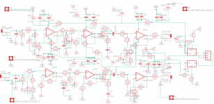
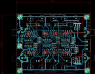
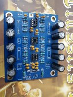
Here are the schematics and board layout, since the schematics are pretty much shared everywhere and I am not selling the PCB/kits commercially so I hope Jim doesn't mind it. Bugle 2 v1.1 with LME49720 DIP and LME49720HA side by side with Emerald and LME49720+BUF634 buffer
Let me know if I should improve something to make v1.4.
Among audio picked up both digital and analog. Will focus on analog in this thread so picked up my old Gararrd 401/SP25MKIV/Sanyo/ Unity/Amstard/Toshiba 3150/Sharp and restored all their turntables, imported few cartridges, washed all the vinyls and wallah back to business.
But one thing in comparison with FLAC in the vinyls was the obvious old and slightly lower quality of preamps, tubes are too much of a hassle for me and designing a preamp from ground-up was too much of an exercise.
Thus I decided not to reinvent the wheel and pickup some of the more affordable and good designs. Bought a bugle 2, found about RJM emerald.
made my own PCBs based upon RJM emerald albeit resistors changed to SMD instead of through hole type.
for bugle 2, owing to my larger collection of turntable decided to make my own PCBs ground-up from the provided schematics thus I designed the PCBs V1.1, V1.2 and now V1.3.
Small differences but V1.3 does not use wallwart and TLE2426, rather LM317/337 combo and for the connector I will be using GX12 or GX16 connectors the board size is 100x80mm and it is a very compact board.
After JLCPCB and their cheater shipping company SF express tried to rip me off by asking me to pay illegal charge/bribe for delivery of the boards I shifted to PCBWAY through Aliexpress and the boards are on the way 10 boards of course. one board for version 1.1 is on the way to simon in UK as a gift.
Here are the schematics and board layout, since the schematics are pretty much shared everywhere and I am not selling the PCB/kits commercially so I hope Jim doesn't mind it. Bugle 2 v1.1 with LME49720 DIP and LME49720HA side by side with Emerald and LME49720+BUF634 buffer
Let me know if I should improve something to make v1.4.
Attachments
Last edited:
OK, due to the way PCBWAY or JLCPCB accepts orders I ended up ordering 10 PCBs of Hagerman Bugle 2 PCB (my own design of PCB).
I only needed a few of them so same way I decided to give away "RJM Emerald PCBs" I have decided to give away PCBs of Hagerman Bugle 2, I think I have 5 or 6 of them which I wont be using. When I say give away I mean absolutely free including shipping.
I however have few conditions and they are:
1) I have just designed the PCBs, I did not design the circuit thus I donot want these PCBs to be sold/used for commercial gains. Whoever gets them must promise not to sell them or get any commercial gains out of them
2) IT would be nice that people getting the PCBs donate some amount to any charity and DIYADUIO, not a compulsion but it would be appreciated.
3) Since I donot have the liberty of free time, I will send the PCBs to no more than 2 people, anyone wanting to have the PCBs beyond these two gentlemen will have to coordinate with them.
4) there are two small errors on the PCB, once you receive them please PM me and I will guide how to fix those errors.
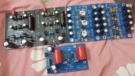
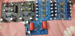
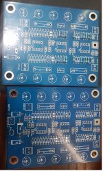
Here is a picture of the PCBs.
I only needed a few of them so same way I decided to give away "RJM Emerald PCBs" I have decided to give away PCBs of Hagerman Bugle 2, I think I have 5 or 6 of them which I wont be using. When I say give away I mean absolutely free including shipping.
I however have few conditions and they are:
1) I have just designed the PCBs, I did not design the circuit thus I donot want these PCBs to be sold/used for commercial gains. Whoever gets them must promise not to sell them or get any commercial gains out of them
2) IT would be nice that people getting the PCBs donate some amount to any charity and DIYADUIO, not a compulsion but it would be appreciated.
3) Since I donot have the liberty of free time, I will send the PCBs to no more than 2 people, anyone wanting to have the PCBs beyond these two gentlemen will have to coordinate with them.
4) there are two small errors on the PCB, once you receive them please PM me and I will guide how to fix those errors.
Here is a picture of the PCBs.
Attachments
Last edited:
I'm not familiar with the program you're using for board layout so can't tell right off -- are you using a standard 2-layer board? and if so are you making a ground plane around the areas that there's no signal on layer 2?
If not you might think about at least adding that ground plane and maybe even going to a 4 layer stackup of sig/pwr - gnd - gnd - sig/pwr or similar. Should help return current pathing to avoid crosstalk between lines -- I think you're getting to the density on the board where you might have some at audio freq's, though I'm not a super expert or anything.
In any case, nice job 🙂
Thanks for the inputs, when I design a simple PCB normally I use Cadsoft Eagle, for complex circuits I use Altium. Since this is a simple and small circuit I designed this PCB in EAGLE.
Circuit topology is simple most of the tracks are on the bottom layer, if there is routing issue then the track is on top layer.
Top layer is mostly a polygon pour connected to the ground plane.
Circuit topology is simple most of the tracks are on the bottom layer, if there is routing issue then the track is on top layer.
Top layer is mostly a polygon pour connected to the ground plane.
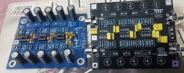
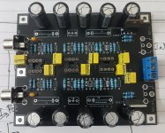
older version with TLE2426 and newer version with LM317/337 as power supply regulators and newer version has provision for RCA jacks on the PCB. The PCB size is 100mmx80mm
Newer version has improved footprints for decoupling capacitors, polyester/polypropylene capacitors in this version versus the ceramic capacitors in the previous version.
waiting for the 220nf capacitors and aluminum casing to arrive so that I could complete the project and put it to test.
Newer version has improved footprints for decoupling capacitors, polyester/polypropylene capacitors in this version versus the ceramic capacitors in the previous version.
waiting for the 220nf capacitors and aluminum casing to arrive so that I could complete the project and put it to test.
Attachments
Last edited:
You lucky guy have LME49720HA! The best audio opamp I have heard so far. And they are discontinued by TI😡
