Sophia Electric SET EL-34

Great sounding El-34 amp. A favorite, but I have too many amps! Works great! Sounds great!

Upgraded input tubes, plus originals, which are quite old.
All tubes included.
Manual included.
Lots of my schematics, accuracy could be iffy...
Original shipping box and styrofoam.

NOTE: cosmetic issue. Right front paint is off and just colored in with black. Looks ok from a distance. Could really use a paint job.

$500 plus shipping and PP fee

IMG_0546.jpg

IMG_0548.jpg
IMG_0547.jpg
IMG_0551.jpg
IMG_0550.jpg

Tube amp of different kind - SRS551

This is my latest creation. It is still prototype. Output transformer is also my build (EI120 x 55mm laminations).


Matej

Attachments

  • RS1003 DN2540 amp.jpg
    RS1003 DN2540 amp.jpg
    68.7 KB · Views: 1,239
  • WP_20180829_17_08_34_Pro.jpg
    WP_20180829_17_08_34_Pro.jpg
    292.5 KB · Views: 992
  • WP_20180829_14_08_27_Pro.jpg
    WP_20180829_14_08_27_Pro.jpg
    313.6 KB · Views: 924
  • WP_20180812_18_00_26_Pro.jpg
    WP_20180812_18_00_26_Pro.jpg
    313.3 KB · Views: 857
  • WP_20180729_17_12_00_Pro.jpg
    WP_20180729_17_12_00_Pro.jpg
    452.2 KB · Views: 937

MMM homepage and blog of Jean-Luc Ohl

Home - Loudspeakers.audio

"loudspeakers.audio is a very new website for online acoustics measurements that I’m working on. Some features are unique : optimised target curve, hybrid correction,… It is now in a trial (and free) phase so if anyone interested can do some tests here. Feedback would be greatly appreciated. "

blog blogohl lots of info about measurements and software etc. (partly in French)

advice for a novice (which power)

Hello,
I would like to approach the world of tube amplifiers, and I would be about to buy my first amplifier to use with a turntable.

I would also combine a couple of speakers that I already have with these characteristics

Type: 2 way, 2 driver loudspeaker system.
Frequency response: 50Hz to 20kHz
Recommended Amplifier: 75W (maximum)
Crossover Frequency: 3600Hz
Impedance: 8Ω.
Sensitivity: 89dB.
Bass: 1 x 165 mm polymer laminate cone
Tweeter: 1 x 25 mm titanium dome.
Enclosure: bass reflex
Dimensions: 375 x 274 x 235 mm
Weight: 17.7 kg
Year: 1987

my doubt is about the power of the amplifier I should focus on.

I have seen a model based on PSVANE HIFI KT88-K3 series of about 45W x 2 (RMS 8Ω) and a model based on PSVANE HIFI EL34 of 8Wx2 (ultra-linear connection).

the environment is a room of about 6x5 square meters.

Can the 8W amplifier be enough or should I focus more on the 45W? it is not my habit to listen at high volume, but it is also true that I would not like to have an amplifier that can only make background music.

Please be patient if my request is a bit too trivial and a bit subjective.

Kind Regards,
Luigi

Tube tester - Centrad 752

I got hold of this beautiful tube tester, my very first. It was advertised as fully working, and seems to be so as well. I haven't heard much about this one, but it seemed to have all the right features, so I went for it.

However, as with all vintage gear, I assume I have to do some fixing unless I want one of us suffer. So I had a peek inside.

I can only find one electrolytic cap, which I assume is used for filtering after rectification. Ok, no issue to replace. I've heard rumours about some types of old solid state rectifiers not being stable - is there any way for me to tell if this is such a type? The tester is from 1957, as far as I know.

Also, I saw some yellow components I didn't know what was, and one of them was chipped. I've attached pictures of those as well.

Apart from that, the power cord is a bit scary (and the chassis all metal), but everything else is in great shape!

Anyone know these?


EDIT: Sorry about the upside down pic. Looked fine until I uploaded.. :O

Attachments

  • IMG_3374.jpg
    IMG_3374.jpg
    1,005.4 KB · Views: 194
  • IMG_3368.jpg
    IMG_3368.jpg
    1 MB · Views: 199
  • IMG_3369.jpg
    IMG_3369.jpg
    801.3 KB · Views: 182
  • IMG_3370.jpg
    IMG_3370.jpg
    1,017.7 KB · Views: 212

JBL Control Subwoofer Set

$300 pick-up in the Seattle area

I ordered all the parts for this in-ceiling subwoofer, but it doesn't fit between the framing in my old house! If you want the full 12" subwoofer sound but doesn't take up floor space, this is the subwoofer; it’s a black box and can also be used in room. I have the woofer and baffle, backbox, and grill with hardware all in the original boxes unused and ready to be installed.

312CS Subwoofer - $447.00
MTC-300SG12 - $43.00
MTC-300BB12 - $231.00

Requency Range: (±3 dB) 34 Hz – 3.5 kHz
Sensitivity: 99 dB in ceiling near corner, 93 dB in center of ceiling
Frequency Response: (-10dB) 30 Hz – 4.5 kHz
Maximum SPL: (1m) 125 dB (low-impedance, 131 dB peak, center of ceiling)
Impedance: 8 ohms
Power Rating : 400 W continuous pink noise (1000 W peak)
Driver: 300 mm (12 in) subwoofer
Baffle/Rim: Metal, driver pre-mounted to baffle, ported.
Ceiling Cutout Size: 378 x 378 mm (14.9 x 14.9 in) (for MTC-300BB12 backcan)
Included Accessories: Ported baffle pre-attached, MTC-300SG12 Grille, square contoured, white. MTC-300BB12 Backbox, 80 liters (3 cubic feet)

Attachments

  • 65EEDF46-38D3-403C-9A6B-B6148C9DB5F2.png
    65EEDF46-38D3-403C-9A6B-B6148C9DB5F2.png
    280.9 KB · Views: 262
  • 2C97E59A-3C9D-4E29-99F0-D054BE871871.jpg
    2C97E59A-3C9D-4E29-99F0-D054BE871871.jpg
    653.3 KB · Views: 258
  • 5B2212C9-54F5-4C9A-91C6-9B2F2A4556DF.jpg
    5B2212C9-54F5-4C9A-91C6-9B2F2A4556DF.jpg
    759.4 KB · Views: 259

AE TD8M/Beyma TPL150/Monocor

I am new to speaker building, although 25 years ago I built an electronic crossover and subwoofer with a friend of mine. I now have the money and the time to try it again. I want to use an Acoustic Elegance TD8M 8ohm, Beyma TPL150 8ohm, and Monacor AIRMT-85 4 ohm with a Hypex FusionAmp FA123 (125W+125W+100W) with DSP built-in. I don't have any experience with a DSP and how to set it up. I've seen Vapor Audio has a TD10M and Beyma TPL150 crossed over at 1050Hz so I will probably crossover at 1100Hz and 7500Hz. Acoustic Elegance recommends a 12L enclosure with a port tuned to 80Hz and a sub picking up at 100Hz.


Does this all make sense? What size port would I need (length/diameter)? I've never used a DSP so I was wondering if there are people who can help set it up. I was thinking about setting up the speakers as ideal and then using the pre-amp DSP for the room correction. We are building a home in northern Idaho but since it isn't built yet, the room correction stuff can come later. Any advice is appreciated. I'm sure one of the questions is why the Monacor tweeter. There are two reasons 1) I didn't want to just copy Vapor Audio and 2) I wanted to see if I could limit the vertical beaming. Most of the time the speakers will be used in home theater rather than critical listening so people won't necessarily be in ideal positions.

What Linear Regulator Chips Have the Lowest Noise Figures?

Recently a forum member (gmphadte) told me that the LM317/337 combo will be more quiet than the L7815/L7915 combo. I looked at the datasheets and don't know how to interpret the 317 ones because they are adjustable. He also mentioned that the quietest option would be a shunt regulator. I looked at the datasheet for a couple of zeners but found nothing about noise in them.

It got me thinking about finding the best +/-15V regulator chips for my op amps. So far, I've found a LM340 that looks to be a better option by a small margin to the L7815 which is what I have been using.

I have mainly been looking at "load regulation", "output noise voltage in uV" and "ripple rejection in dB". Are all voltage regulator chips going to have the same specs or is there a plus/minus pair that is the best for low noise? Should I be focusing on different specs?

Is it true that a zener will have the lowest noise of all regulator chips and the only advantage of an IC regulator is for it's safety features like short circuit protection and thermal shutdown?

Tube rectifier advantage

I just acquired a Fender Brownface Deluxe guitar amp manufactured in 1962. It's my first amp I've been exposed to with a tube rectifier. I've realized there's another positive benefit of utilizing a tube rectifier over a solid state type, ie no "standby" switch is required. Since the rectifier tube warms up at the same rate as the other tubes, B+ isn't applied until everyone is thermionically eschewing electrons. That's a very nice automatic feature eliminating the manual standby switch.
This amp uses two 6V6 output tubes in push pull. The tremolo is to die for. It modulates the output tube bias. I think it's easily the best tremolo I've ever heard.
It's a great "small venue" rock guitar amp in that it will break up at tolerable volume levels yet has a reasonable clean level on lower settings.

Tubelab SSE - coupling caps and run capacitor

Hi all, thanks first for a great forum. I've lurked a long time, learned a lot, and just finished my first build, a Tubelab SSE. It sounds fantastic and many thanks to George for a great design and instructions. (I'll try to attach a picture of my amp just to show off!)

I don't know much about electronics, so I have two questions... first, what sort of difference would higher quality coupling capacitors make? I see some of these special caps (Auricaps etc) for $10-15 each. I just bought really cheap ones, maybe $1-2 each from Mouser, before spending more. How much difference does it make? Also, I bought fairly small output transformers (Edcor GXSE 10-8-5) so would this be more of a limiter and not worth buying better coupling caps?

Second, I have an optional run capacitor, but for aesthetic reasons didn't want to use an ugly mouting bracket so I superglued it to my chassis top (yes, I know, the advanced assembly technique of superglue). But this means it's not grounded. I can test a few volts between the capacitor housing and ground, and I know for safety I should ground this, so I have some copper wire wrapped around it temporarily until I think of something else. But my questions is whether that small amount of voltage seems normal or some problem with the capacitor?

Also, I measure B+ at around 479 volts. Does that sound right/safe?

Thanks in advance.

Attachments

  • ampfront.jpg
    ampfront.jpg
    368.1 KB · Views: 725

FS: 6V6GT Amplifier Board Stuffed and Ready

This is amp board for the Dynaco low power amp. It is stuffed and ready to hook up. The cathode caps are SilmicII and the coupling caps are orange drop. $45 plus shipping.

Paypal friends and family.

Shipping is from Vienna, Austria.

Thanks!

Attachments

  • IMG_6505.jpg
    IMG_6505.jpg
    571.5 KB · Views: 778
  • IMG_6506.jpg
    IMG_6506.jpg
    588 KB · Views: 773
  • IMG_6507.jpg
    IMG_6507.jpg
    651.6 KB · Views: 728

Newbie: advice? Luxman L-350AII

Hello All,

First post here.

I am looking for advice for jumping into my audio journey for real. I saw a Luxman L-350AII listed for sale for $1900 online and was interested Luxman from what I can gather is a reputable amp maker, although pricy and putting more emphasis on aesthetic than other companies. However they always grabbed my attention.

Luxman L-350AII Pure Class A Integrated Amp | On a Higher Note

It would seem that this amp is the same amp as the 550AX except it was put together in China to reduce costs.

What I am looking for right now is something that is higher end and newer so it will last without worry or repair for a long time. I plan to use an amp for listening to records, piping my TV sound through, and Bluetooth audio via a dongle maybe.

Let's get to the fun stuff.
Here is what I have so far in my limited and vintage audio journey so far...
Receiver/amps:

Sansui 4000
Kenwood from the 70s ( unsure of model and I'm not home)
Generic Yamaha entry level receiver

Speakers:
Boston acoustics a150
Boston acoustics a400
Bose bookshelf speakers 201
An old pair of Polk bookshelf speakers

Not too impressive but that is what I could find locally for cheap. I am young still and don't have much money, but I want to take the plunge, any advice or conversation would be appreciated! Thanks!

P.s.
Anyone that knows whether that site is legit would help too haha

FS: audioharma cable cooker 3.5

FS: audioharma cable cooker 3.5.... SOLD SOLD SOLD

For sale is a few years old audio harma cable cooker 3.5. This is almost brand new and has only seen leas than 300hours use. The top was scratched up on storage but functions perfectly. It comes with all the accessories needed. Asking $800.00 but open to best offers. Will ship from Chicago... thanks

Attachments

  • BAE4856A-A650-4DD8-B4EB-53107EA2D3D5.jpg
    BAE4856A-A650-4DD8-B4EB-53107EA2D3D5.jpg
    1,010.3 KB · Views: 296
  • 051A9CB8-6FEC-4176-B730-2B58E971366C.jpg
    051A9CB8-6FEC-4176-B730-2B58E971366C.jpg
    1,010.8 KB · Views: 275
  • 7FDAD695-1D21-4AB0-A76A-39FC56D9D7CA.jpg
    7FDAD695-1D21-4AB0-A76A-39FC56D9D7CA.jpg
    1 MB · Views: 270

FS: Edcor matching transformers

I have 10 new Edcor WSM 600/2.4K matching transformers. These can handle a 0.5 watt / 10 volt signal. They provide a 2:1 step up in voltage.

I used them with balanced outputs on the direct output of a DAC (signal split with half riding on a DC minus leg and the other half riding on a DC plus leg). The transformer would sum the halves and cancel the DC so no capacitors were necessary (although a small RC low pass was added as a reconstruction filter). It worked nicely. Although they do have a "bit of their own sound" they are much more affordable than the competition.

I paid about $15/unit and they are new but have been sitting in a box for several years. The shipping would be about $5 per box (box can hold up to 10). I will sell for $15 per pair plus shipping. If you buy all 10, I will let you name a reasonable price.

I have problems shipping stuff out of the USA, so no international sales (sorry).

Thanks,
-Tom

Do i need filters for Visaton FRS 8M ?

Hello,

This is my first project, it consist in using a board with:
- TPA3116 D2 -> High Efficiency TPA3116 D2 Dual Channel 50Wx2 Amplifier Module DC 4.5 27V Digital Power 2 Channel Stereo Amplifier Board|Integrated Circuits| - AliExpress
- two Visaton FRS 8M 3.3 inch drivers
- 3d printed internal labyrinth with wood sides

As far as i understand, i need a power supply of 19V @ 3-4 A, or something like that.

Question: my drivers are full range-ish, but if i look at their output curve, the low-end stars from around 90 Hz, so using my logic, it would be useful ( and good ) to use a high-pass filter to cut-off anything below 90 Hz ? Or something like that.

So, what filter(s) do i need ?

Two Way bookshelf speakers advice - crossovers

I'm looking to build a pair or low-ish profile two way bookshelf speakers. I possibly intend to wall mount them.

I've built up the crossovers on VituixCAD and I've noticed that the impedance is hitting a low 2ohms at about 4khz. Is this going to be a problem for driving them?
I'm currently using an old Onkyo TX-SR705 amp with certainly is fine with 6 ohm speakers but maybe wouldn't do so well with 4 ohm?

My drivers are:
Tweeter - Dayton Audio RST28A-4
Mid/Bass - Dayton ND105-4

Please see the crossover image.
Crossover Only: dayton-pc-speaker-crossover-diagram — ImgBB
Crossover + Graphs: dayton-pc-speaker-crossover — ImgBB

*EDIT for different picture link*

New Ohmite Metalfilm Resistors Mox700

Just found on mouser:
Ohmite Mox700 Metalfilm Resistors
Classic Throughhole 1/4W

Quote:
Ohmite Mox700 High-Precision Metal Film Axial Leaded Resistors offer tight tolerances down to ±0.02% and a low-temperature coefficient of resistance (TCR) down to ±5PPM/°C. Ohmite Mox700 Axial Leaded Resistors offer a 10Ohm to 1MOhm resistance range and a power rating of 0.25W at +70°C.

Considering the specs prices are ok 1,8€ +/- 0,5€ (Mouser Germany without VAT)

edit Mouser global link
Access to this page has been denied.

directly to the shop
Access to this page has been denied.

Datasheet
https://www.mouser.de/pdfDocs/res_mox700.pdf

Hello from the UK

Hi everyone
Just a quick introduction before I post a querry for some advice.
Not a total newbie to this subject as I built my first crystal set some 40 years ago with numerous projects including breathing life back
into the odd valve radio.

It's only until now that I decided to design and build a valve stereo amplifier out of the parts I've collected over the years. It sounds good, well to my ears anyway but working on it for possible improvements now requires the advice of those far more knowledgeable than I. Any help would be greatly appreciated. Cheers

High Voltage Boost Converter - sacrilege?

s-l500.jpg

This is a
DC 12V 24V to DC 200-450V 70W High Voltage Boost Converter Step Up Power Supply.

I am using one of these to feed an ECC83 and two EL84's 250 volts.
Output irons are Lundahl.
Toroid custom wound for heaters. Big one.
Power supply for eh... power supply is a big one from a car stereo demo rack. 13.7 volt regulated, good for about 20 amps.
The sound is super duper and it is absolutely dead quiet between songs.
Have ordered one more for dual setup.


Have anyone tried something like this?
Is it ******* at the Alamo? Swearing in church?
Cannot find much online.
Weird. Its awesome!

Ceiling speakers used as floorstanders

Not sure if this is right place to post this but here is what I got. I have a pair of Polk RC80i in ceiling speakers that I was going to install in ceiling of Livingroom but plans changed and the return window expired. So I thought that it would be cool to use them in a cabinet as floor standers to be powered up by a Schiit Aegir amp. Not sure if these would be good for a setup like that. I think they are decent efficient speakers. Just not sure size and design of enclosure to make them sing. Any thoughts?

OPT Trafo

Hello all.
I have stumbled upon a old looking OPT and have no idea what it's specs are or where it came from. I guess its from the 25 (ish) watt range. All I can tell it has a faded lable with anode, screen and CT taps on the primary and all I can make out on the secondary is a 15 ohm tap for shure. There are two other numbers: 3020 and MA 307
The core (EI) is about 95 X 80 X 34 mm. I have googled it with no joy.
Hope anyone can help.
Cheers, Carl 😕

Help me understand my room's acoustics

Hi guys,

I want to better understand the acoustics of our livingroom and based on that, see what kind of changes I can make to improve the acoustics. I had a previous post about designing a loudspeaker, but I;m taking a step back to first understand the room before I continue with the new design.

First of all some info about the room. It is an open plan with livingroom, open kitchen and diner room in an L-shape. The wall to the backyard is mosly of glass. We have very thin curtains that give some privacy, but allow light to enter. They don;t do anything significant for the acoustics.

This the floorplan.

This is where the sofa is located. The speakers are on both corners, but next to the TV. The speakers are the KEF LS50 wireless. I have a subwoofer with 13" driver in closed box.

In the next post, I will share the measurements. So in first post is just some info about the room.

Attachments

  • Floorplan.png
    Floorplan.png
    260.9 KB · Views: 254
  • IMG_4103.jpg
    IMG_4103.jpg
    622.8 KB · Views: 254
  • IMG_4102.jpg
    IMG_4102.jpg
    565.3 KB · Views: 239
  • IMG_4101.jpg
    IMG_4101.jpg
    596.9 KB · Views: 245
  • IMG_4104.jpg
    IMG_4104.jpg
    835.8 KB · Views: 235

Help me fix this Oscilloscope (kikusui)

I bought a Kikusui COS6100 oscilloscope and it was working fairly well for a while (some minor HV supply problems that probably cannot be discussed here).

Anyway one day I turn it on and it has this weird sorta bloom effect. For some reason it would only happen if the trace was moved to the bottom half of the screen.

I suspect its some kinda interference issue as it is affected by the 20MHz bandwidth limit button (?).

So, today I was messing around with some pots on the CRT board and one of them seemed to fix the problem. But it actually just shifted the problem from the top half of the screen to the bottom (so now the trace displays fine when at the top half, and when moved down it messes up).

Here are some pictures of me moving the trace to the "bad area" on the screen (the trace isnt as blurry as it looks 🙂):

First pic (good)
second
third
fourth
fifth (worst)

It is not affected by timebase, voltage setting, channel, brightness, probe setting, etc.

thanks

PCB slot type housing?

Hello:

I bought a phone preamp PCB on eBay that has no mounting holes. It may have a ground plane so I think I'll avoid drilling holes in it. It's a simple circuit so I assume only two-layer copper.

I have seen enclosures made of either an extrusion and cover, or 4 extruded plates and screws, that have slots to hold PC boards but am not finding many choices...unbranded random sizes online.

The board is 100 x 220 mm.

Any suggestions for slotted enclosure, or edge clips to hold the board in an oversized chassis?

I had the awful thought of double-sided foam tape.

Any suggestions are appreciated.

Thanks

Murray

Mute for Tube Preamp

I've built a 12b4a tube preamp and absolutely love it. I think the final piece of the puzzle is the mute switch upon start up. I have a 30 sec timer switch controlling a signal relay on the output. I'm using the attached design I found from an earlier post. It works perfectly and quietly upon startup, but on shutdown I get a pretty good pop. Not terrible, but would still like to stop that from happening. Just for reference, this is installed after my output capacitors and before the final 1M resistor to ground. Any suggestions?

Attachments

  • Preamp-Mute.JPG
    Preamp-Mute.JPG
    76.2 KB · Views: 546
  • preamp.JPG
    preamp.JPG
    60.5 KB · Views: 477

ESS Model 400 / 500 Watt Power Amp

Though I posted this thread in the Pass Labs forum, I thought this may get better attention here and seemed more appropriate.

I recently acquired this power amp with an unknown history but learned through a member on the Audiokarma forum that I might find info on this site. The amp claims 500 watts or 250 per channel, weighs considerably and appears very well built. After cleaning up the exterior I opened it up and found the transformer was loose and some small black plastic pieces were on the bottom of the chassis along with some small but long machine screws. Removed the screws, vacuumed up all the plastic bits, tightened down the bolts securing the transformer, traced those screws to the back of the output meters, sprayed the pots with Deoxit then visually inspected the circuitry for any abnormalities with all appearing fine. Another thing, those heat sinks extend way out and have sharp edges, I've the scratch marks on my arms to prove it!

Powering it up using a DBT with a 100 watt bulb and 8 ohm dummy load per channel with gain pots set at a minimum, the bulb was first bright then momentarily darkened then came back on at about 3/4 the original brightness. there was no Magic Smoke or explosions! That's about all I had time for today but it looks like a promising project.

Found some info on the bias and offset from a restorer online who thought it should be set to 100mv but this applied to the model 200, haven't found much info on the model 400. Do you think the 100 watt bulb is insufficient for testing this powerful amp or should it be a greater wattage? The transformer is massive and rated at 1.5 killowatts, pretty intimidating and approached with caution! I've some info on this and will have to read it carefully before proceeding further but so far don't see any info on how to go about setting the bias or offset, any info regarding doing this would be most appreciated!

Attachments

  • P1340086.JPG
    P1340086.JPG
    460.5 KB · Views: 627
  • P1340089.jpg
    P1340089.jpg
    478.7 KB · Views: 714
  • P1340090.JPG
    P1340090.JPG
    738.7 KB · Views: 778
  • P1340096.jpg
    P1340096.jpg
    382 KB · Views: 515

Audio Research SP-5 recap question

Mornin' Oh wise ones...

Not exactly a DIY but close enough I trust.

I'm in the process of recapping a crusty SP-5's electolytics and wonder if anyone has any thoughts on replacing the Elpac capacitors with something different or shall I leave well enough alone. Auricaps, Dynacaps etc worth putting in there? Couple of ceramic disk capacitors as bypasses to the main power supply electolytics to something else? Recommendations?

Thanks,
Brooks

Layered 1d slat diffuser

Pardon me if someone already posted about this idea, but
i havent been able to find it anywhere. I have read about someone
who came up with the the idea of building a 1d slat diffuser in both
directions so that it ends up being similar in function to a BAD panel
(Binary amplitude diffuser)

Well.. My brain came up with the idea of what if you went 4 levels or

more deep at say 22% coverage each layer with strips of 2x2. Would
that create almost like a large skyline diffuser but with absorption in the
unfilled squares??

FS: ASC Japan 100 uf motor run cap

These are ASC Japan 370 VAC rated motor run capacitors. Bought these from Sharon at Midori Farm in 2005ish( for those of you who may remember her ). Obviously no longer in production.
4 5/8 inches tall not including the lugs
2 1/2 inch diameter

Price is $ 40.00 each. These make fantastic filter caps in a tube PS.
I have four.

Shipping on the buyer. I will ship the cheapest way possible that can be insured. ( UPS, USPS Priority mail ). These are heavy so shipping will be few bucks.
If you buy more than one I'll take $ 5.00 off each cap.
I can't post pictures, so if you're seriously interested PM me with your e-mail and I'll send them directly to you.

Stay safe

Crazy Bill

18sound NSD1095N v's B&C DE250

I'm using a B&C DE250 in an 18sound XT1086.

Very smooth. Great dynamics. But I'm missing some very small signal detail that I'm used to on my Esotars.

I've tried the waveguide (horn?) with and without the open-cell foam. Better without the foam IMO in every way. (equalized in both configurations- flat to 17 kHz).

Has anyone tried the top of the line 18sound driver?

I can eq with DEQX.

So I'm looking for the smoothness of the B&C, but with much more detail (shimmer on cymbals, triangles e.t.c., rosin on bow/strings).

I'm not into HT. Stereo, music, only- not at ultra loud levels.

David

4k 60 fps android box?

Hi Folks; I'm looking for an Android box (or something) to playback 4k 60fps movies from an external hard drive. I have ordered cheaper units from 'over seas' sources and had 0 for 3 luck; either couldn't play 4k, couldn't produce 60 fps, or simply did not arrive.

It seems like the Nvidea Shield would be a safe bet, but wondering if there are less expensive alternatives as my only requirement is playback from a downloaded library.

Need enclosure design software advice after reading through the forum

Hi all, I'm new here to the forum and so I think I am probably behind the curve a bit in a lot of the discussions here. Some of the great threads have some longevity to them!

I don't really do anything very advanced. I've been using BassBox for what I need and it seems to be ok. I noticed that the latest version 6 hasn't been updated since 2013. That maybe isn't a terrible problem in some cases.

I came here looking for recommendations on whether to still with BB6 or if there is something better out there. What I found is a LOT of software options including some lengthy lists. But nothing that really has a good comparison of features vs price vs ease of use. So maybe that is what I really am looking for. Is BB6 still a decent package for the price (sub $500), or is there something better?

Pete Millet's NuHybrid amp - Help diagnosing buzz/hiss in right channel

I've just completed a built of the NuHybrid amp from Pete Millett. Nice little amp, very interesting sound so far. Had some serious issues at first which were solved by grounding the pot. But there's a subtle-yet-noticeable hiss in the right channel, and I'm not entirely sure how to fix it. My EE knowledge is pretty limited, so I don't even know where to begin when it comes to diagnosing and fixing the issue. If anyone is willing to help me figure this out, I'd surely appreciate it.

EDIT: OK, here's an update: I've just verified that it's NOT just on the right channel. It's equally hissing in both channels, even when the volume pot is turned all the way down.
Maybe that knowledge will help us figure this out?


I'll put a link to Pete's page about this project here, which contains lots of information including the schematic. I'll also post a picture of my build.

Thanks!

NuHybrid Headphone Amp

An externally hosted image should be here but it was not working when we last tested it.

Aleph Ono Project (from PCB group buy)

Because the two other threads about the Aleph ONO PCB group purchase are a bit misleading from name, I started this new thread for all information regarding this incarnation of the ONO.

I will try to answer all questions about the PCB in this thread, rather than emailing each buyer individually. Please ask questions here, not by email. For example, I got at lease five emails about the 10uF capacitors on the board. But my time is limited. If someone else can help on questions about the Ono, please do so.

First thing to publish is a parts list (MS Excel format) . It was checked twice, but may still contain errors. If You find one, please post here. If You compare it to the original Ono schematics, You will find some differences. I will try to explain:

- the drivers for the relays is on the power supply board
- You can place a resistor in series with the relay coil to use 24V or 12v relays
- R 2 in schematics is R43 on my board (as in the original Pass placement print)
- R 28 in schematics is R10 on my board (as in the original Pass placement print)
- C29 in schematics is C25 on my board (as in the original Pass placement print)
- R 12 (from gate of Q3) in schematics is R1 on my board (as in the original Pass placement print)
- C? in schematics is C48 on my board (as in the original Pass placement print)
- Q21(right one, is double) in schematics is Q22 on my board (as in the original Pass placement print)
- C7(power supply) in schematics is C17 on my board (as in the original Pass placement print)
- R 61 (from gate of Q20) in schematics is R58 on my board (as in the original Pass placement print)

I suggest that everyone who builds one with this PCB, does a printout of the schematics and changes the parts description. These changes were necessary to keep the board layout as close to the Pass ONO.

coffin, Raka, Elio: please post Your questions again in this thread.


-Peter

12V 2A CLC Filter values for a noob, 0.4mH?

Hi,

I'm looking to build a filter for an off-the-shelf 12 V DC linear supply from Tripp Lite. The supply is really 13.8V at 5 amps. At $60 it's relatively cheap.

It's going to a DAC/headphone unit which requires 12 at 2A but will be closer to 3-4 Amps when headphones are connected.

Based on ancient and dusty knowledge, ill gotten, I planned to use 100uF, 0.4mH/0.2 Ohm, and 100uF as a good starting point. This is somewhat convenient as I have lots of left-over coils from crossovers, and hopefully still have lots of leftover Panasonic FM caps.

I was thinking of trying to drop about half to a volt across the inductor at maximum current.

What do you think of the overall plan?

Best,

Erik

question of heat?

What areas are most prone to heating up the most inside your fairly common A A/B amplifier?

Looking at an amp I'm already obligated to buy since I paid for 1/3 of it. The top is a light very light silver. But then I could barely notice an unusual discoloration on the perforated top. I'm just hoping it was not mistreated by having the pre on top or some other component.

Component stacking is a pet peeve. If its for the heat or footer circles that get left behind 😡

PSpice for TI

Today is the official launch date for "PSpice for TI", a new free simulation tool that we (TI) made in collaboration with Cadence.

https://www.ti.com/tool/PSPICE-FOR-TI

It does require a MyTI account to download.

Some features of PSpice for TI:
1. The simulator is built on the PSpice platform from Cadence. However, unlike previous free versions of PSpice, PSpice for TI has no node limit. So you can simulate large circuits if desired.
2. The built-in library includes >5700 TI components, and is automatically synchronized to our website. New product releases automatically appear in the library.
3. Spice models from other vendors can be imported.
4. The main "limitation" of the free tool is if your schematic includes a spice model from a non-TI vendor, you are limited to 3 simultaneous measurements.
5. PSpice for TI schematics are compatible in Cadence's other products (e.g. Allegro PCB layout)

Frequently asked questions:
Q: What does this mean for TINA-TI?
A: TINA-TI will continue to be supported. We have a very strong user base for TINA and feel that PSpice for TI compliments it well.

Q: Does PSpice for TI work offline?
A: Yes, the only requirement for an internet connection is for library updates.

Q: Are Spice models from TI compatible with other simulators?
A: Yes. We go through a lot of work to make sure our models can be successfully imported into other simulators and the simulations will converge properly. That doesn't change with this launch.

FS Ian Canada Digital modules

Selling my Ian Canada Modules as per below. any Questions please ask!

ES9038Q2MPiDualMonoPlus £30
IVSTD board £10
LL1544aTranformerIV no transformers £10
Bisesik Transformer I/V board £70
ESScontroller £15
ESScontrollerExtensionKit £5
FifoPiUltimate with Crystek 24.576M/22.5792M clocks £65
LifePO4MkII £70
ANR26650M1-B 2500mAh - 70A LifePo4 batteries x10 £20
TransportPi £20
UcAdapterKIT £10
UcMateConditioner with 2 x Maxwell ultra capacitors £25
UcHybrid 3.3v x 4 with 8 x Maxwell ultra capacitors £75

All in good working order!

USB scope for sale.

I have a couple of spare 10 mega sample/s USB scopes to pass on.

Maximum +/- 2 volts max input only.
Voltage ranges are "125mV", "250mV", "500mV", "1V" per division.
You can read much higher voltages with x10 and x100 scope probes.
Max +/-20v with x10 probe.
Max +/-200v with x100 probe

Comes with Windows PC software on CDROM.
Time bases are "25uS", "250uS","500uS", "5mS", "10mS", "50mS"
FFT display.
XY mode.
Single shot and roll modes.
Free run, positive and negative trigger modes.
Print traces. Save trace to bitmap file.
Save and load traces.
Data logger can save screens over a period of time then play them back.
Good up to about 100KHZ sine wave so ideal for audio work.

£18.99 each plus p+p
p+p is £4.99 to UK, £12 to Europe and £19 to USA/ Australia


scope.jpg

A practical illustration of thermoelectric effects

I am currently building myself a small, autonomous and easily moveable ammeter.

I already have plenty of current-measuring means, mainly multimeters and also more exotic ones, like a HP428 clone, but I felt the need for another one.
Multimeters generally lack some ranges, and my 7½ digit dreadnought is often used for other purposes.

The one I am building has eight ranges, from 1µA to 10A, and just two terminals.

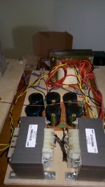
This means that the 10A shunt needs a relay, because the miniature range selector I used is just good for 1A.
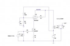
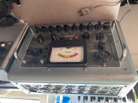
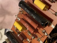
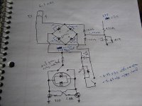
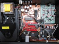
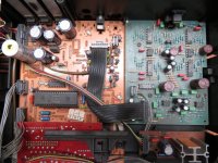
Nothing fancy: just an old 10k pts DPM, some shunts, logic, 4-wire circuitry and a precision 10x amplifier to bring the fsd from 1.0000V to 100.00mV.

The circuit was debugged, and I began the calibration.
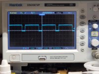
At first, everything seemed normal, but I then noticed that the zero of the 10A range was slowly drifting upwards, reaching 5 pts after half an hour.
I was somewhat puzzled, because the conditioning circuit is common to all ranges, and has nothing switched.
All of the other ranges were rock-steady.

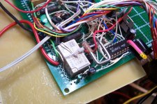
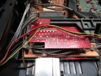
I then realized that the relay consuming 0.04A @5V was slowly heating, and heated one side of the 0.01Ω shunt.

When shunts heat due to the current they pass, they do so in a uniform manner, meaning thermoelectric effects tend to cancel, but here only one side was (lightly) heated, and this was sufficient to cause problems.
As the resolution is 10µV, 5 pts translate into 50µV.
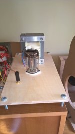
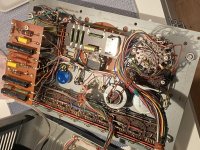
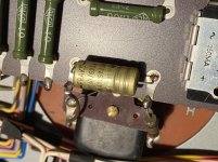
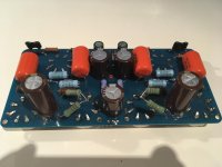
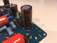
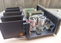
As a result, I included two compensating junctions, made from kovar/copper.
One is on the top of the relay, and the other on its left side:

attachment.php


The result was a zero perfectly stable from the switch-on instant to ∞.

This shows that thermoelectric effects are not confined to ultra-precision circuits: they can show up in the most mundane and ordinary situations too

Attachments

  • TempComp.jpg
    TempComp.jpg
    407.3 KB · Views: 128

indicator light using filament 6.3VAC voltage

I just uploaded a schematic of a circuit, and I need some help with it. The LED is a two color indicator, that is powered from the 6.3VAC filament supply for a 12AX7 tube. The LED indicates the condition of a "fat" switch that feeds the plates, and it is controlled by a switch operated SPDT relay. The schematic only shows the indicator circuit. This all worked before I had to change the ground reference. The two 100 ohm resistors used to connect directly to ground. How do I get the indicator working with this new arrangement?

Attachments

  • IMG_5214_opt.jpg
    IMG_5214_opt.jpg
    27.7 KB · Views: 439

Transistor linear region equal to linear gain region ?

Hi I'm looking at this transistor datasheet MJ15024. I was looking for a Ic/Vce diagram for linearity but it does not provide it. But they do provide a current gain / Ic graph. Would it be correct to say that the linear part of the gain is the linear part of the transistor ?

Thx

Attachments

  • 2021-04-14 15_49_16-MJ15022 - Silicon Power Transistors.png
    2021-04-14 15_49_16-MJ15022 - Silicon Power Transistors.png
    90.2 KB · Views: 221

What was the first Complementary AB bipolar amplifiers?

I realised the other day that while I know many of the milestone points in amplifer design (Loftin-White, Williamsone, JLH etc) I have no idea of the history of the classic complementary AB transistor amplifier (as typified by the 741 op-amp)
a) first proposed complementary bipolar AB (or class A)
b) first successfully implemented it as an audio power amp
c) first used the venerable 2N3055/2N2955 pair in a product

Was it NatSemi or Philips? Or someone in Japan? Even "The Art" just assumes it is too obvious to bother attributing the design to someone.

DAC thermal migration of non-harmonic distortion

Hi

Sinewave spectral measurements on three different RME Multiface 1 showed some expected static spikes emerging from the noise carpet as harmonic distortion, along with some others, unexpected static spikes not correlated to the input signal. And also, there were some rather strange, shifting spikes, steadily moving upwards on the frequency scale while the device was warming up.

For further investigation and better delta temp during the first minutes of poweron, I therefore cooled the Multiface box down to 10°C before connecting it to the power supply for ne next set of measurements. Note that the graphs show cumulative max values measurements over 30 (early measurement over the first 10 minutes) and over 100 cycles (up to a total monitoring time of approx. 1 hour). The measurement were done with a sampling rate of 88k2. Switching to a sampling rate of 96k showed a slightly different spikes pattern.

MF1_Dynamic.gif

On the gif you will see the main spike of the 1.5kHz looped-back test signal along 3 spikes of it's 2nd, 3rd and 5th harmonic distortion.

Then there are these other spikes which are not related to the test signal, but certainly related to the DA-AD process (Looped back SPDIF instead does not show any spikes except of the test signal): Such an unexpected, static cluster of spikes is seen at > 20kHz. And then there is the wild bunch of these shifting spikes. The speed of theirs migration is higher during initial warmup, steadily slowing down while the device gets warm. Definitely very strange seems the spike emerging at approx. 250Hz, but only after some 10 minutes of warmup and then steadily wandering upwards the frequency scale, reaching some 1200Hz after an hour or so.

Does anybody have an idea about these thermally dependent, shifting artefacts? I would like to understand the cause of these artefacts in order to eventually get rid of the worst of them (as is, dominating the "regular" THD products of the DA-AD process).

Attachments

  • MF1_Dynamic.gif
    MF1_Dynamic.gif
    102.8 KB · Views: 213

PT for stereo 2A3..?

Hi

I will soon start building a stereo 2A3 amp.

I have looked around the web and only found 1 choice for the power transformer. The Hammond 302AX. All the other Hammond don’t have 2.5V windings.

The other option was Edcor XPWR067, would of been perfect but it was withdrew from their list. I contacted them and they won’t reinstate that model...😡

So any recommendations besides the 302AX ?

My other option is to buy a PT which doesn’t have the two 2.5V windings and buy two separate Triad F1-X.

TIA
Eric

Clarifications on the "noDAC" DSD DAC from hdmi input

Hi everyone, Im' new here so I don't know if I should open a new thread... You'll tell me eventually!

Anyway, I read from some forums including this one that it's possible to convert a digital dsd stream to analog by means of a "simple" analog filter, without really involving any digital chip or clocks. This seems intriguing, and some swear by the quality of the sound (especially on some Italian forums).

I'm thinking of building one to connect my sony bluray/sacd player which unfortunately only outputs pure dsd via HDMI cable, to my vintage Sansui SS amp.

Here's the idea:

1)Convert HDMI stream to I2S as it looks more manageable, and there seems to be more documentation regarding noDACs DACs with I2S protocol input

2)Apply a filter, maybe (maybe?) with 30kHz of cutting frequency (-3dB)

3)Preamplify everything with a jFET or (even better?) a tube buffer stage

4)Connect to power amp and hopefully enjoy my SACSs finally in a purer form than the usual poor analog output my internal bluray DAC sends out


So, the problem here are the many questions (I am really sorry for such a long list):

1) Is converting to i2s necessary? Or is it even a good idea considering i'm planning to use a commercial (probably chinese) i2s extractor sold on ebay? I don't think it will heavily affect the audio as it's just a protocol conversion, and many people including audio enthusiasts use it...

2)THE FILTER! People say that even a first order filter is fine, but I really doubt that it will be enough... The phase response, the low slope... I just don't know. What type do you suggest me? I read about Chebysiev or Butterworth filters, I was thinking to a Butterworth, probably to a 3rd or 4th order. Is it sufficient? Plus, I don't know if I want to start to mess up with opAmps, so possibly an RL or RC or even RLC circuit... Do you have maybe some premade plans or some figures for the values of resistance capacitance and inductance?

3)The preamp: The thing I can't find anywhere is the expected output voltage and impedance from the i2s output and consequently the average or peak voltage out from the filter... Some values maybe? Consider the aux input @ the amplifier is 150mV 47kOhms @1000Hz... How much gain and amplification are required?

4)Can anybody redirect me to some apparently tested, good projects? Or maybe some calculators/formulary to to the maths. I'm a soon to be engineer so I can grasp some calculations (and would be happy to avoid you doing them 😀), but consider electronics is not my field...


I thank you all for your kindness :worship: and sorry again for the long message

Bryston 6B original - Overheating channels, distorted output

Hey DIYers

Desperately need some help with a Bryston 6B.

Have been fighting with this one for a while. Upon turning on, the amp module on the right immediately gets hot (hotter than comfortable to touch within a minute). Output on both channels is distorted. Here's what I've done so far:

Removed all of the outputs transistors and tested them on a tester, all seemingly test good

Replaced all capacitors on the rear input board, as well as fresh power supply capacitors and rectifiers

Replaced some of the coupling capacitors on amp board (mainly the electrolytic ones)

Adjusted the bias to specs (had to work quickly before I felt unsafe letting it get any warmer)

doing the best I can with 7B schematics since this thing doesnt exist on paper or in pdf files. Any suggestions of where I should look next? Its REALLY hard to probe around this thing with a scope.

thanks
Caleb

I've narrowed down my OT options: which to pick?

I've been looking around for Output Transformer options, and there's not a lot in my price range that's currently available anywhere.
From what I've read, I can expect good sound from Edcor. I was trying to avoid them at first, due to the 10-12 week lead time on new orders. But I'm thinking that it might be worth the wait.
So I've narrowed it down, I believe, to two options.
Help me decide between the two:

First, the option my pocketbook likes best: GXSE10-5K
For less than $100, I'd get my amp up and running.

Second, the "high-end" choice. CXSE25-5K
After reading about these on George's site, I get the impression they will deliver lots of power and bass, without compromising the high frequencies. I dig all that. But is it worth the extra dough? Should I shell out $200+ for these big boys?

I'm also open to other options if anyone has other suggestions.

Mosfet 2SK134/2SJ49 (luxman L58A)

Hello everyone,


I recently acquired a L58A, with the right channel down.


After testing the mosfet, one of the 2 2SK134 tested bad:


I tried finding for 2 pairs of 2SK134/2SJ49 , not an easy tasks.


I decided to replace them with 2 matched pairs of ECF10N20/ECF10P20.


While the specs are very similar the input capacitance differs.


Anyway, i would like to have your point of view on this replacement.


Will it be a drop in, or do i need the change the value of the resistor R273 and the cap C704 before the mosfet.


DyzQFEyTEIUBAAAAAElFTkSuQmCC

thanks a lot for your time!


Etienne

Mission PCM 7000 Enquiries

Good evening,

This is my first time ever using old audio equipment and I'm a little lost.
I recently found an old Mission PCM 7000 in my house and was trying to figure out if it was still in working order.

From the fair amount of troubleshooting I've done - I've gathered that there are a few abnormalities:

1/ It will have trouble reading some discs. It can take anywhere from a few milliseconds to about ten for it to display the CD's information.

2/ It may display the CD's information but will then not be able to read the disc, or will take longer than it should.
These discs all work fine on more recent digital sources.

3/ Sometimes when reading a disc it will make a low humming or buzzing sound. And usually the "ERROR" message will appear.


I hope I've made myself clear enough. I will include some pictures of the bits and bobs inside.
It all seems to be in good condition, the only problem I've seen is that one of the green sticky tapes (no idea what they are for) fell on the red board and left some sticky residue.

Any advice would be greatly appreciated, thank you very much for your time.

Attachments

  • Inside PCM (1).jpg
    Inside PCM (1).jpg
    166.8 KB · Views: 401
  • Inside PCM 2.jpg
    Inside PCM 2.jpg
    280.5 KB · Views: 289
  • Red Sticky Board.jpg
    Red Sticky Board.jpg
    246.4 KB · Views: 264

Tube/Valve identification

Hi. I’ve just signed up to this forum and this is my first post. I’ve come across an old packet with a bunch of tubes in them but I have no idea what they are/whether they’re worth anything etc. I’d be grateful if those in the know could assist and let me know your views. I’ve attached a picture of one of each type of tube that’s in the packet.

Thank you!

Attachments

  • 51B018DC-18B1-42F6-B33D-94AEE4C1D3AA.jpg
    51B018DC-18B1-42F6-B33D-94AEE4C1D3AA.jpg
    640.3 KB · Views: 113
  • CF8D7AB4-8152-4CD1-87C3-02CDEF0B2B1D.jpg
    CF8D7AB4-8152-4CD1-87C3-02CDEF0B2B1D.jpg
    309.5 KB · Views: 98
  • FAD9CA32-121B-44F3-BABA-ED12C12CBD41.jpg
    FAD9CA32-121B-44F3-BABA-ED12C12CBD41.jpg
    621.1 KB · Views: 99
  • 9749C8CC-776E-41F0-A31D-6ECAF39D6A75.jpg
    9749C8CC-776E-41F0-A31D-6ECAF39D6A75.jpg
    420.7 KB · Views: 93
  • 32E9162E-44F1-4777-B9B3-D89E87A44BF0.jpg
    32E9162E-44F1-4777-B9B3-D89E87A44BF0.jpg
    368.6 KB · Views: 98
  • 21E7B748-75D7-4072-B7AF-987CB0E7EA09.jpg
    21E7B748-75D7-4072-B7AF-987CB0E7EA09.jpg
    381.8 KB · Views: 82
  • 2CD38141-63FE-45AF-A979-A150B5E691E5.jpeg
    2CD38141-63FE-45AF-A979-A150B5E691E5.jpeg
    543.9 KB · Views: 76
  • 0B225097-ADCE-489E-B4C9-6E523825FFAC.jpg
    0B225097-ADCE-489E-B4C9-6E523825FFAC.jpg
    554.7 KB · Views: 71

Help with cheap guitar amp

I have a cheap hybrid guitar amp. Beth I get A108. It has a 12ax7 input and SS output.
It is NOISY. So noisy that I can even use headphones with it. 60hz it sounds like. Louder with volume.

I can’t find a ground loop problem, and I tried an alternative power for the tube heaters without any change.

The transformer has what looks like a center tapped main winding. Two yellow, one brown. The brown (center) is tapped to the SS output, referenced to one of the yellows, for 13v and a full wave rectifier. The yellows look to give 26v to a half wave rectifier, I assume somehow powers the tube.

I don’t have a schematic, and probably won’t be able to map it from the PCB. I just hope to make the noise tolerable and am looking for suggestions. I can’t help but think it is the power supply.

Or maybe the amp just sucks.

Any help is appreciated!

The biggest baddest documented design for a 4inch?

Im trying to build a set of cabinets for my girlfriend using the generic 4" chinese drivers and would like to know what exotic designs are out there thats for squeezing the most bass out of these tiny units. Because she likes bass, lots of it, and i wanna satisfy her ��

Edit: already tried tabaq and fh3 in the past and tho theyre great i'd like to build something different

Class A in itself benificial?

In the past I was critical about the benefits of Class A in poweramplifiers mainly due to the vast resources of material (big powersupply, heatsinks..) and environmental footprint.
I saw Krell (plateau biasing) Jeff Rowland (Class D amps) moving away from too much Class A enrichment and believed Class A was something of the past.
After I had the opportunity to possess amplifiers like the Threshold SA/1 and Levinson ML-2, I realized that for me the benefits outweighed the "penalty's".

I recently acquired a pair of fixed bias Krell KRS-200 mono poweramplifiers that are biased for approx. 180 Watts Class A RMS @ 8 Ohms
(375mA with 18 outputdevices = 364 Watts peak Class A and 182 Watts RMS)

I've read the technical articles from the PassLabs website:
- Leaving Class A and the Sweet Spot both written by Nelson Pass on the Class A subject.

My question is if the conclusions in those articles are also true for my Krell KRS-100 an amplifier that consumes approx. 650 Watts when idling, has comparable heatsinking and PSU and Class A ratings comparable with a PassLabs XA-160.5.

I'm not implying I bought a PassLabs quality amplifier, I didn't of course, but I'm just curious if the reasoning in those articles are true for my amps and any amplifier that is a high (fixed) biased amplifier?

Thanks in advance.
https://www.diyaudio.com/forums/attachment.php?attachmentid=935852&stc=1&d=1616763191

Attachments

  • IMG_2988.jpg
    IMG_2988.jpg
    672.1 KB · Views: 1,136

LC filter after diode bridge

I built a DC power supply for about 12V (not critical) loaded by a constant 2.5A. The reservoir capacitor is 100000uF, but still there is too much ripple. I came to the idea to insert a choke between the diode bridge and the capacitor, forming an LC filter. I found a small laminated core choke with DC resistance 1.5 ohms. Since the DC voltage on the capacitor is 14.5V, I calculated the voltage would be 10.75V with the choke inserted.
However, I measured 7V DC on the capacitor. How it could be?
I know the choke should have an air gap for not going into saturation, but how does it affect its DC resistance? Why does it drop more voltage than I expected?

J270 P fets NOS

Would anyone have interest in some NOS J270 P Fets, I have several thousand of them NOW from when I worked at Audio Research Corp. Mouser sells these for $3.58ea so they are still available new. I would be open to some offers/trades for some as i have 10 lifetime supply's of these for personal use LOL I would just never use them all.

PM me with interest/offers.


Zc

New, unused Angela Universal Power Transformers 300b

Back some time ago I had ideas of building some monoblocks. I had acquired these very robust power transformers from Angela. They are T540932.

Primaries can be wound for 120V or 240V.

Secondaries:

HT+ 380 - 320 - 0 - 320 - 380 @200mA (with a 55V bias tap)
Heater 1: 5V @ 3A (suggested for GZ37 Heater)
Heater 2: 6.3V with CT @ 3.5A (suggested for pre-amp + driver)
Heater 3: 5V with CT @ 1.5A (suggested for 300b)

I have two of these (one per channel) New, never used. Still unpainted too. Original Angela circuit diagrams are included as well.

Some inspiration:
JE Labs Arkiv (up to 2008): JE Labs SE300B Classic and Deluxe

Now the bad news: These babies are kinda heavy. They are about 5Kilo Each, and I would really prefer to sell them as a pair.

Economy Shipping (for the pair - with Tracking and WELL packed) within Europe (including the UK) will cost around 50 Swiss Francs. To the USA around CHF 100 Swiss Francs.

PM me if you are interested. They are probably still not so expensive as other Power Transformers, are really nice looking and are decent quality. Ok, they need paint.. 😉

For reference, the 300BX from Hammond is fairly similar in specs, maybe not quite as nice build quality and costs at least $175 new (each). I hate to let these go, but need to slowly reduce. My loss is your gain.

Attachments

  • SE300BF7002.jpg
    SE300BF7002.jpg
    65.2 KB · Views: 301
Projects by fanatics, for fanatics
Get answers and advice for everyone wanting to learn the art of audio.
Join the Community
507,766
Members
7,887,630
Messages

Filter

Forum Statistics

Threads
406,190
Messages
7,887,630
Members
507,766
Latest member
Coreque