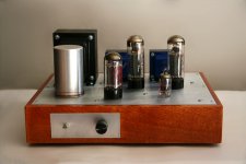
Hi all, thanks first for a great forum. I've lurked a long time, learned a lot, and just finished my first build, a Tubelab SSE. It sounds fantastic and many thanks to George for a great design and instructions. (I'll try to attach a picture of my amp just to show off!)
I don't know much about electronics, so I have two questions... first, what sort of difference would higher quality coupling capacitors make? I see some of these special caps (Auricaps etc) for $10-15 each. I just bought really cheap ones, maybe $1-2 each from Mouser, before spending more. How much difference does it make? Also, I bought fairly small output transformers (Edcor GXSE 10-8-5) so would this be more of a limiter and not worth buying better coupling caps?
Second, I have an optional run capacitor, but for aesthetic reasons didn't want to use an ugly mouting bracket so I superglued it to my chassis top (yes, I know, the advanced assembly technique of superglue). But this means it's not grounded. I can test a few volts between the capacitor housing and ground, and I know for safety I should ground this, so I have some copper wire wrapped around it temporarily until I think of something else. But my questions is whether that small amount of voltage seems normal or some problem with the capacitor?
Also, I measure B+ at around 479 volts. Does that sound right/safe?
Thanks in advance.
Attachments
pboard,
Your tubes look like EL34 from the picture in your post, so 479 volts would be on the high side for those. If you don't have a choke, you might consider adding one - it will help with improving the power supply section and dropping the voltage to around 450v, which should be ideal. A small choke like the Triad c-14x can be hidden under the chassis.
The Edcor GXSE has been used with success by quite a few builders.
Jpjones, good idea. I hadn't thought about mounting with the bracket inverse. I actually might like it sitting lower. Just would need to cut the hole precisely to get a nice fit or maybe dress up the joint with some sort of simple wire or rubber ring.
Another question for anyone... How hot is ok for the amp? After about 30 minutes of playing, my top plate around the tubes gets hot enough that I can only touch it for 2-3 seconds. Sound normal? The transformers are fine. Opts get warm due to proximity but not terrible.
Perry
Another question for anyone... How hot is ok for the amp? After about 30 minutes of playing, my top plate around the tubes gets hot enough that I can only touch it for 2-3 seconds. Sound normal? The transformers are fine. Opts get warm due to proximity but not terrible.
Perry
Another question for anyone... How hot is ok for the amp? After about 30 minutes of playing, my top plate around the tubes gets hot enough that I can only touch it for 2-3 seconds. Sound normal? The transformers are fine. Opts get warm due to proximity but not terrible.
Perry
I think this is normal for an SE amp as the tubes are operating at their full potential
ALL of the time unlike a push pull amp.
Nice neat build by the way
")
I measured my available space. Just barely 2.25 inches that might fit the larger choke.
Ok, here's my attempt at understanding some of the circuit...I see the larger choke has 150 ohms resistance (as is the R1 optional resistor) but my choke has only 50 ohms. If the larger choke doesn't fit and I were to keep the small c-24x, would it work to add a 100 ohm resistor somewhere in the circuit to lower B+ voltage a bit? If so, where? In series with the choke?
Perry
Perry-
Yep, in series with the choke. Make sure it's a high wattage resistor (5W+). 100 ohms will only eat a few volts though. I actually did just this on a SSE build to keep things closer to George's spec'd choke but I've since removed it because I wanted a little extra B+ and I figured it was just generating heat.
You might also consider other rectifier tubes that will drop more voltage than the GZ34. Depends on how much current you have on the 5V tap and potentially your value for C1. A 5U4 will drop 30V more than the 5AR4/GZ34, but it needs a 3A heater and it probably wouldn't very much appreciate the spec'd 47uf C1 value. Tougher to change the heater current, but the cap would be easy to swap. It would put you right in the 450V sweet spot.
Perry, 480v is a bit higher than most, but not too high. What size cathode resistors are you using (R17/R27)? The tubelab website has a table that shows the predicted dissipation for different tube types for a given B+ and cathode resistance. An increase in cathode resistance decreases the dissipation and makes life easier on the output tubes. Pushing them too hard is probably not "unsafe", but it will decrease their life expectancy.
The heat generated on the top plate is a little concerning, however. My SSE runs a high B+ too, but it gets nowhere near that hot. Is the heat coming directly from the tubes or from underneath the top plate? Is the pcb right up against the plate? Are you certain that all of your resistors are rated high enough (R17/27, R18/28 in particular)? They could produce heat if they aren't.
Good job though, just take care of that motor run cap and it will look great!
Thanks. I will check those resistors. It is possible they are a source of heat. I bought the exact specs from the website but worth another check. Is there any downside to getting resistors rated for higher wattage? Like if the spec says 2 watts for R18/28 and I get ones for 5 would it be cooler?
My knowledge of tube circuits and measurements is limited. I'll spend some time this weekend looking more at the voltage and cathode resistor values. I am also looking to replace my cheap coupling caps with nicer ones, maybe trying a slightly higher value (.47) just for learning/comparison. On this topic, any difference between caps that are called "crossover" and ones that specifically refer to coupling? If it's got the right value and voltage, does it work the same? Or are some just for speaker applications?
Perry
No downside to components rated for higher watts besides a lighter wallet and possibly less room on the board. I don't think there would be much upside though.
I'd suggest that you should try to fully understand the table of simulation results on the Tubes and Applications page of Tubelab's website if you don't already. It's important to understand what's going on with the output tubes but it's a source of confusion for many of people.
The Zload column is the primary impedence of your output transformer (5K in your case). Rk is the resistance of the cathode resistor (R17/27). If you match those two with the correct B+ voltage table, you can get an idea of the tube dissipation. The maximum dissipation for EL34 tubes is 25w. If you have 480v of B+ and a 560ohm cathode resistor, then your tubes are running over 30w, which probably isn't good. You'd want a 680ohm or even a 750ohm to keep your tubes happy. Sorry if you already know these details, but others may find it useful.
If you want to see the effects of different capacitances for the power supply caps, try messing around with PSUD2. It's pretty easy to use and a good way to understand the power supply circuit.
Sorry, no clue about crossover vs. coupling caps.
Happy tinkering!
Dave
Dave, very helpful. Thanks. I will spend some time on this. I did try a few calculations after measuring cathode voltage last week at about 30.6 volts and my cathode resistors are 560 ohms so that would be about 55 mA and then I thought I came to about 25 watts after assuming plate voltage similar to B+ and subtracting cathode voltage, then multiplying by 0.055. But I've mixed up a few measurements after replacing R1 with the choke. I'll try again and also check out the simulator.
I really appreciate the help here. Much of the fun is learning new things. I studied art for undergrad and then MBA for business so ohm's law was new for me in this!
Perry
I really appreciate the help here. Much of the fun is learning new things. I studied art for undergrad and then MBA for business so ohm's law was new for me in this!
Perry
Quick update. I temporarily added a 150 ohm 5w resister in line with choke and brought B+ down to around 164. Better, but I will still try to get a bigger choke in there. I also think I'm understanding that I just picked the 560 ohm cathode resistor without really looking at those tables. I see how I probably need a bit larger there so will try that next to manage the tube dissipation.
Perry
Perry
...brought B+ down to around 164.
Sorry. Typo. Meant 464
Dave, very helpful. Thanks. I will spend some time on this. I did try a few calculations after measuring cathode voltage last week at about 30.6 volts and my cathode resistors are 560 ohms so that would be about 55 mA and then I thought I came to about 25 watts after assuming plate voltage similar to B+ and subtracting cathode voltage, then multiplying by 0.055. But I've mixed up a few measurements after replacing R1 with the choke. I'll try again and also check out the simulator.
I really appreciate the help here. Much of the fun is learning new things. I studied art for undergrad and then MBA for business so ohm's law was new for me in this!
Perry
You definitely have the theory and math correct. So if those measurements still stand, then your tubes are running where they should with the 560s. George's simulations and your observation of excess heat makes me skeptical of your reported cathode voltage though, so you might want to check that again.
And you're very welcome for the help. I couldn't have completed mine without this forum.
No downside to components rated for higher watts besides a lighter wallet and possibly less room on the board. I don't think there would be much upside though.
Actually, there is - resistors can be sacrificial components. On my TSE, I've had a few instances where things have gone wrong and resistors burned out rather than my tubes, or my OPTs. Up-rating components willy-nilly is not a good thing to do - the designer chose component ratings for a reason.
Actually, there is - resistors can be sacrificial components. On my TSE, I've had a few instances where things have gone wrong and resistors burned out rather than my tubes, or my OPTs. Up-rating components willy-nilly is not a good thing to do - the designer chose component ratings for a reason.
Good point. Thanks for the post.
You definitely have the theory and math correct. So if those measurements still stand, then your tubes are running where they should with the 560s. George's simulations and your observation of excess heat makes me skeptical of your reported cathode voltage though, so you might want to check that again.
Yes, I'm skeptical of myself! Here's what I measured again tonight, with a bit more detail. Tell me if I'm either measuring wrong or if there are other things that could help...
B+ at 462 volts (seems to ramp up to around 460 then creep slowly higher). I am measuring this at the end of R4 closest to the edge of the board, or for more convenience I'm also measuring this using the T2-PRI connector (red wire to my output transformer).
Output tube cathode voltage 30.4, measuring using the octal socket pin closest to R17 or R27.
Does this sound right? It doesn't seem to be in the same range as George's simulation tables which seems to show cathode voltages higher for that range of B+. (As mentioned before, I'm using 560 ohm cathode bias resistors.)
I also tested the driver cathode voltage at 2.0 volts, measured at the pins horizontal to the board on each side.
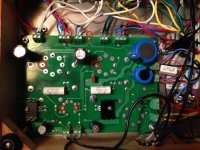
I attached a picture of my amp interior, with circles hilighted where I tested voltage. Note also the extra resistor I added in line with choke to reduce B+ from high 470s down to 462-464.
Is there something else I can measure to help affirm things are ok or not? Where does plate voltage fit into any of this? I will say, the amp sounds great! So I'm happy, but still feel the question is whether something is off and I'll wear out the tubes or other components given the B+ and possible high temp.
For context, I'm using an Allied 6K7VG power transformer and Edcor GXSE10-8-5k output transformers. And all JJ tubes: EL34, ECC81, GZ34. I'm not using solid state rectification (don't even have the diodes on the board).
Thanks again!
Attachments
All the other measured voltages and how you got them seem correct to me. PSUD2 predicts 455V of B+ with an additional 150ohm resistor, so 462V sounds reasonable. Have you checked the secondary voltage on your PT to see if it's running within tolerance?
In my very non-expert opinion, you're probably good to go. Sorry if I worried you. Perhaps someone else can suggest a way to verify everything, but I can't. Enjoy your amp!
In my very non-expert opinion, you're probably good to go. Sorry if I worried you. Perhaps someone else can suggest a way to verify everything, but I can't. Enjoy your amp!
- Status
- This old topic is closed. If you want to reopen this topic, contact a moderator using the "Report Post" button.
- Home
- More Vendors...
- Tubelab
- Tubelab SSE - coupling caps and run capacitor