Tda 2030/2050 chip amp powered by usb power bank

I have long wanted to build a system out of battery power supply, because it's fun, also no risk of electric shocks, with lots of ready assembled circuit board and great quality caps and resistors for tuning of sound.
So I bought a pair of TDA 2050 amp boards, and a usb wire with built in 5v to 12 v dc to dc.
When i connected them initially i wonder how bad the quality of the sound. But it turned out to be ok though no much resolution and dynamics. And loud enough to drive my small pair of Boston acoustic A23 speakers.
I hv changed some of the caps and resistors to make the sound to be quite nice.
I hv been more on diy esp with the minutes bt speakers just to learn to work with surface mount devices. I don't know how far I am from the current hifi, but if i were to get the most up to date system, it may not be fun as a lot of my preferences were still from 1960-90s as i am in my mid 60s

Attachments

  • mmexport1632387141984.jpg
    mmexport1632387141984.jpg
    402.8 KB · Views: 255
  • mmexport1634263536687.jpg
    mmexport1634263536687.jpg
    575.9 KB · Views: 236
  • 20211024_151714.jpg
    20211024_151714.jpg
    318.2 KB · Views: 416

Questions about the inputs/outputs on the diyA PSU board

The labeling of the outputs on these boards has always confused me. Electrically, it seems like there are two inputs (+, -) and two outputs (V+/-, gnd). But the labeling has more names for these four points. For example:

The positive input has D+, D++, and D+++, but also three connection points for "ST_IN1".

The output has V+, V++, and V+++, as well as ST_+, and three more connections labeled "1, 2, 3"

On the ground side, there is the "ST_G1" set of connections, as well as one labeled "GND2.2"

I assume there are meanings to the various sets of connections, but I don't understand what they are. Is "V+++" better than "V+"? Is there a difference between "GND2.2" and "ST_G1"?

I know these are stupid questions, but please have patty on me 😱

Puzzle Coat for the Dayton PS220-8 with Dayton DS215 8" passive radiator

Fostex FE206en or Dayton PS220-8

I did a build with the Dayton PS220-8, full range driver, paper cone reinforced with Kevlar and the Dayton DS215 8" passive radiator. Referenced above, with thanks to the diyAudio community. The drivers are in a repurposed pair of KEF Q80s(34 liter volume).

It's been 3 years, so now I'm looking for another project. I'm interested in using the dave from planet10 Puzzle Coat(AKA Mod Podge) for the full range driver and passive radiator. I've done a search of cone treatments, and the major threads are overwhelming with he number of post and lack of consensus.

So for my driver and passive radiator, can I expect a positive change with the puzzle coat?

Thanks, Joseph

Shorted meter leads, now no power, where start fixing?

I was adjusting the left channel of the input board on my BA-3 when two of the meter leads made contact (I'm not sure which). The fuse didn't blow, the the amp immediately lost power. I measured ~250mV to ground on the positive supply and ~90mV to ground on the negative side. I pulled one of the filter caps from the positive supply, and it's reading 0uF. Nothing looks burned or charred.

What should I test, and what is most likely blown? Both power supplies? More?

Quad midrange panels for bass?

I'm considering modifying a pair of quad 63s by adding an extra pair of bass panels - but what I have to hand are a the mid-range panels. As far as I can see, if I just connect the delay lines together so that the panel work as a single unit, they should function the same as a bas panel.

Any comments on this?

On the conversion from 4 panels to 6 - I have read a few threads on this, and many of them go into a lot of detail on the delay lines, termination values.... and then end by saying it should work just fine. Is it really as simple as this?

WTB: Victor's 1khz signal generator any version (in US)

I'm looking for one of Victor's 1khz signal generators if anyone has one laying around that they can part with. I'm going to purchase a new one when they're available again but need one somewhat soon in the meantime. I'm in the US in 95648. I can pay for shipping and pay for pickup so you don't even have to do anything 🙂


If you have some other kind of extremely low distortion/noise signal generator for less than US $300 I'm also interested.

Tapered array questions

Hi.
Interested in tapering an array of 10-12 small (3”) full-range drivers, for improved response towards the center of the array, which will be at ear level.
I searched the forums snd read Jim Griffin’s “,white paper”, and am leaning towards either a 3,2,2,3. Or 2,3,3,4 type connection of drivers.

The key here is that i wish to place a small treble unit at the center of the array.
Anyone have experience here and/or can give advice on techniques/resources?

Thanks

Jetway PC player - first one please advise

Here’s what I currently have:
My main computer built in 2012 w/ gigabyte Mobo and E3 xeon chip, 8 gig Ram and 2 HD’s (no ssd’s) Running windows 10 64 and Jriver 23. My DAC is a firewire fed from pcie card to a Mackie blackbird DA/AD interface which will stay part of this computer for REW measurements and recording…

My plan:
I told myself to buy a dac last and although I still don’t have a preamp I’m buying a new dac. Everything else is in place, speakers amps… It is now a revealing system. The dac I’m getting, (Gustard x26 pro) according to a reviewer, says it’s not that noticeable of an improvement when adding a preamp with this dac. Like better cables that will come down the road.
From what I read and watched about a server and an audio player combo is that it is the best way to get low noise / jitter and so on having the server do file management and the player doing only usb out playback. I don’t have a LAN switch. I was thinking of connecting the two pc’s directly with a LAN and have both pc’s running windows 10 and Jriver. I know Jriver can be set to play both roles. I decided to go with windows because I already have a Jriver windows license and I don’t want to learn a new OS right now. One less variable.

Here’s what I bought/on it’s way:
Jetway NF894G32 mini ITX with Celeron J3455 chip
Crucial 8 gig DDR3L 1866 ram
Intel 660p M.2 512G SSD
Case
Windows 10 64

Planning on buying:
Gustard X26 Pro
Matrix Element H USB Pcie card
Matrix usb cable
Small Green Computer 5v-12v 25 watt linear power supply with (2) outputs.

My questions:
The only thing I could find on the Jetway is that the processor is 10 watts. The USB card (> or = 1200 mA) will be powered by the external PSU so aside from the M.2 card and RAM nothing else will be plugged into it. I’m guessing that 25 watt will be enough but it’s only a guess. Anyone have any experience with these? Any other comments, tips or tricks would be appreciated.

FOCAL Alpha 80 - no sound

FOCAL Alpha 80 - no sound - finish please delete

Hello everyone. I got an active monitor Focal Alpha 80, after two years it stopped working. When the power is turned on, the relay clicks, but the red LED remains lit, no sound. Did anyone have such a problem? Can you advise me what to do with it? Of course, I did not find the service documentation anywhere. I tried to disassemble the speaker, I measured the converters, they are fine, according to the catalog, I measured on the TDA power amplifiers whether there is a DC voltage at the output (pin 14), everything is fine. Thank you in advance for the advice.

First Project: vintage acoustic suspension drivers

Hi there! this is going to be my first speaker project 😛😛😛😛
Been reading this forum for two yers now, so thanks for all the info gathered here!!
I want to do a full range so I don`t have to worry about high order crossovers and concentrate myself on box design.
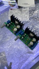
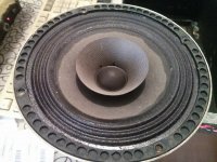
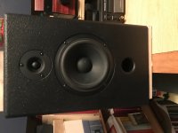
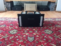
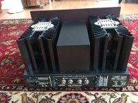
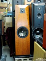
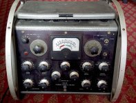
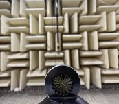
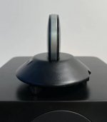
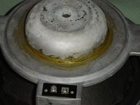
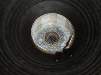
This are 6" acoustic suspension drivers with cloth surround and whizer, prob 30-40 years old, but they seem new and measure fine, Fs is about 73 Hz without brek-in vs the 67 Hz advertised at the time. The other parameters that came in a paper on the drivers box are:

-->Power: 20W rms -->Freq. Resp: 40-16000 Hz -->Fs: 67 Hz -->Voice coil diameter: 1" -->SPL: 97dB/1Watt/60cm --> "High compilance".


The suggested box has 14 l inner volume.

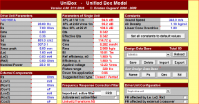
I measured the Thiele Small parameters with arta using added mass method and both measure pretty close, despite Vas and related parameters were even 30% different for different measurments of the same driver. I can do more measurments later but i believe this should suffice to get an idea of what may work here... This are the TS parameters for one of the drivers using stepped sine mode both times:

Fs = 74.24 Hz
Re = 6.00 ohm[dc]
Le = 128.49 uH
L2 = 440.12 uH
R2 = 13.79 ohm
Qt = 0.57
Qes = 0.64
Qms = 5.46
Mms = 3.42 grams
Rms = 0.291736 kg/s
Cms = 1.342902 mm/N
Vas = 28.40 liters (from sucesive mesurements seems to be more like 25 L )
Sd= 122.72 cm^2
Bl = 3.860937 Tm
ETA = 1.74 %
Lp(2.83V/1m) = 95.76 dB

Added Mass - Constant Bl Method: (not sure why this was ticked :bfold: )
Driver unbaffled
Added mass = 11.00 grams
Membrane Diameter = 12.50 cm

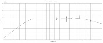
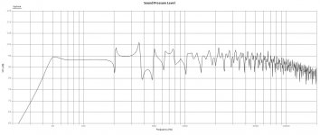
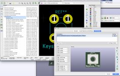
If I simulate this on Leonard TL app as a tappered line, its a wonder, or at least thats what it seems to me, planar from 60-7K, with little ripple, slowly fading , having arround -6dB at 20K. Driver displacement rise to a little bit more than 2mm below resonance and after that its like IB. But i believe this are low excursion drivers.
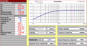
If i SIM it in the suggested sealed 14 lts cabinet of course Fs rise to about 140 Hz but driver displacement is only like 0.8 mm max.

and so the FAQ begins:

Does all this info gives us an idea of wich the value of Xmax may be?

Is there a way to know how much output will the driver produce in the TL before start distorting like a champ?

Is it "clever" to make the TL with a hipass electronic filter or eq to chuck frecuencies below resonance and so be able to get more bass output (above res)?

How can u get over with phase differences from driver to "terminus" in a TL?

Lastly: Is cone displacement less for an aperiodic design than for a TL?

Firstly, i was inclined to make a sealed box, since acoustic suspension drivers are a rare gem and that was its original purpose. Well, that would be the case if VAS was bigger back then (maybe stiffness of drivers varies with age) so it was >3*14 lts. Not sure how you call a sealed box with Vol = Vas/2, maybe just sealed IDK 😀. BUT then, i just clicked on the wizard thing in Leonards app to get a tappered line and i liked what i saw BUT Xmax 😕 .
The idea here is to make the better box for the drivers and me the one who takes compromises. Althogh I believe my 26 years old ears will find the sealed ones lacking in the low end (because of industry ported inclination over the past decades) and i find 140Hz just a littlle high for crossing a sub later, maybe i should give a chance to the "transient heaven" of a sealed enclousure and by the way get more output. Essentially, i dont know about the viability of the TL, if it will produce enough output in a 3.5x4x3 mts room (wich is an approx standard room volume here)or so. Thats enough as im starting to rant... SO,

Where do u see this driver working?

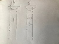
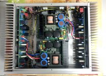
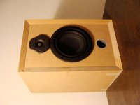
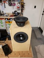
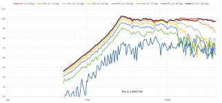
Below you will see a driver pic, a TL (1.15 mts) and a Sealed (14 lts) SPL graph.

Feel free to post and not answering a single question xD.
Cheers!

Attachments

  • sealed.jpg
    sealed.jpg
    68.1 KB · Views: 526
  • TL.jpg
    TL.jpg
    76.3 KB · Views: 527
  • 12806114_10207351863412081_3698080688858702998_n.jpg
    12806114_10207351863412081_3698080688858702998_n.jpg
    112 KB · Views: 523

KiCad 5.1

I just upgraded from KiCad 4.0 to 5.1. I did it to fix an annoyingly sensitive zoom when using my apple magic mouse.

The difference between KiCad 4.0 and 5.1 is nothing short of spectacular. The new version is mind-blowingly fast, much easier to use, incredibly good to look at, wonderfully stable, and the routing options are just fantastic. You just click on a pad and move the mouse through your intended path, and the router does it, respecting clearances as you go and making things beautifully clean.

Pick up a component in PCB and it's highlighted on the schematic. It makes designing beautiful boards so incredibly easy

And the 3d renderings are just absolutely fantastic. It understands step files, so getting 3d models in is a doddle. Component management is much improved, the libraries are _huge_, and totally straightforward to add to.

This is a killer PCB CAD program. I've used Mentor, OrCAD, Protel (since DOS days), Altium, and Cadence professionally. I have spent decades smacking my head on the desk trying to make PCB CAD tools do what I want. KiCad is the absolutely best one I have ever used. It's everything I need with none of the crap I don't.

And it's free. Totally free. No limits, no nagging, no licenses, no dongles. Free. The file formats are also free and fully documented. It works on Mac, Windows, Linux, everything.

Go download it and have a play. You won't regret it.

Attachments

  • Screen Shot 2021-02-08 at 1.07.06 pm.jpg
    Screen Shot 2021-02-08 at 1.07.06 pm.jpg
    561.6 KB · Views: 653
  • Screen Shot 2021-02-08 at 1.06.07 pm.jpg
    Screen Shot 2021-02-08 at 1.06.07 pm.jpg
    588.7 KB · Views: 634
  • Screen Shot 2021-02-08 at 1.05.12 pm.jpg
    Screen Shot 2021-02-08 at 1.05.12 pm.jpg
    935.1 KB · Views: 638
  • Screen Shot 2021-02-08 at 1.01.27 pm.jpg
    Screen Shot 2021-02-08 at 1.01.27 pm.jpg
    538 KB · Views: 640

Tweeter Level Resistor Placement In XO

I built these using SB13PFCR25-8 and Peerless DX 20BF00-4. A former member of the forum helped me with the XO even though no measuring/modeling capabilities here. These seem to be pretty well behaved drivers. I know many will beat up on my XO due to lack of measuring/modeling but I am well pleased with the sound. I would like to mount the XO inside the box but the board is too large partly because I used a variable L-pad. Would the best way to adjust tweeter level be to add the resistor before the XO in the tweeter circuit? Credit to Michael Chua for the cabinet design used in his Sparrow. It seems to fit the SB13 well even though he used the 4 ohm version. Thanks for any and all suggestions.
https://meniscusaudio.com/wp-content/uploads/2020/03/SB-Acoustics-SB13PFCR25-8-Data-Sheet.pdf
Peerless DX20BF00-04 Tweeter

Attachments

  • IMG_0194.jpg
    IMG_0194.jpg
    523.6 KB · Views: 105
  • IMG_0208.jpg
    IMG_0208.jpg
    529 KB · Views: 115
  • IMG_0209.jpg
    IMG_0209.jpg
    536.6 KB · Views: 111

Bad RCA 7199/6GH8A tube?

My dynaco sca 35 seems to hate RCA’s 7199 and 6GH8A.

When I bought my sca 35 on ebay, it came with one original dynaco 7199 and one RCA 7199. The circuitry is original. I did swap out some caps and all the power tubes.
Later on, I found it would loose one channel’s output only when it is hot, and I swapped 7199 of two channels, the issue follow the one channel with RCA 7199. Then, I ordered 2 presumably “new” 6GH8A tubes with adapters. Unfortunately, it came with one RCA and one GE. I found the RCA 6GH8A has the same issue with the old RCA 7199 tube.

It only happens when it is hot. I guess it is related to heater-cathode leakage.
What do you think.

The " Forbidden" Topology! Arm Wrestle the Devil

Hopefully the click bait is worthy enough.
Grab your arm chair and start screaming at the screen.
How Dare You Use the Forbidden Topology !!!
.

Reading some articles from some known Guru
Claims the (CFP) Complementary Feedback Pair Output Stage with Gain
Should be Avoided. Expect to Experience =

High Frequency Unstable
Thermally Unstable
High Distortion
Open loop Disaster

Worse yet, to get eyes to roll more. Toss in a OpAmp to drive it.
And you have what many considered some sort of abomination.
Never to have audiophile appreciation or acceptance.
Just arm wrestle the Devil for eternity


Well I ignored most the advice.
Decided to play with this Topology anyways.


So using a typical fancy OpAmp and a CFP stage with gain.
Very Small gain, Basically a gain of 2.
I can get rid of the typical voltage swing losses you get from
Mosfets. And get pretty close as possible to Rail to Rail swing
from a 36 volt regulated power supply. or +/_ 18 volts.
Without CFP gain. I dont think it goes much more than 28 volts pp
With Gain, almost to the Rails 34.6 volts pp
* edit ( schematic updated in OP and posted in #26)
older OP garbage still in attachments


993111d1635294656-forbidden-topology-arm-wrestle-devil-cfp-gain2-jpg


So much for the Myths of using Opamps and CFP with Gain.

Driven to Clipping its pretty close to rail to rail @ 34.65 volts

At full clean power @ 8 ohms Distortion is pretty good

@ 1 kHz .0005 %
@ 20 kHz .006 %


992742d1635127715-forbidden-topology-arm-wrestle-devil-harmonic-profile-forbidden-jpg


There you go.
2nd and 4th are high. Im sure you cant hear them @ -95 dB
really " horrible " topology

Having some Horn Loaded speaker projects coming up.
I needed something clean for 3 or 5 watts.

This gets up so close to the rails, should be good for 20/30 watts

Did I mention .0005 % distortion @ 1 kHz ?

Attachments

  • OPA1612ForbiddenMosfet.JPG
    OPA1612ForbiddenMosfet.JPG
    84 KB · Views: 1,180
  • CFP with gain 1.jpg
    CFP with gain 1.jpg
    40.5 KB · Views: 738
  • CFP FB example.JPG
    CFP FB example.JPG
    72 KB · Views: 733
  • Harmonic Profile Forbidden.jpg
    Harmonic Profile Forbidden.jpg
    143.7 KB · Views: 924

Input impedance vs hum/buzz

I just restored a dynaco st-70, original PCB.
I notice there is noticeable 120Hz hum. If I remove the input rca cable, the hum is gone. The dynaco st-70 should be ok. I never used an amp with 470k input impedance like the st-70 has. The source is a modern AV receiver’s preamp-out. Both receiver and the st-70 have 2 prong power cords. Thus, there is no ground loop. I tried to tie a ground wire between their chassis. It did improve a little bit, but the hum was still noticeable. I am probably going to add a 10k resistor paralleling with 470k in st-70 if I cannot find a good solution.

BTW, my speakers have 92dB sensitive.

Any suggestions to deal with high impedance input noise issue?


Thanks!

FS: Turntable cartriges Denon 103 and Ortofon 2M blak/blue needle.

Hey
1. Denon 103
I bought it 2019 summer, not used mutch maybe 10 records
I dont have original box (daughter wanted to play with this).

Price:

2. Ortofon 2M red body with
Ortofon 2M blue needle - shape is good
Ortofon 2M black needle - this i bought 2020 summer and it is good as new.

Price:

Shipping preferred in EU
Sorry all sold

1st stage optimal plate resistor and current

Hi. I am designing an hifi amplifier a simple stereo 1 gainstage and 1 phase inverter, and a push pull kt66 based on the leak 60 strereo.


I wanted to know because I am designing everything from scratch. How could i determine the value of the plate resistor. By looking at the tubes datasheet, i understand it is kind of arbitrary and should be decided depending on the distortion thd and to the amount of voltage we want to swing.


But in practice how do i design for the lowest amount of noise and lowest thd, is it even possible ? As using a bigger plate resistor equals more noise, but less distortion ? conflicting.


Thank you.

Classe Audio DR-3 Class A Amp

FYI

Just finished calibrating one of Dave Reich's classics the Classe A(udio) DR-3 power amplifier.
A technician had serviced this amplifier for a friend of mine because the railfuses kept blowing when the amp was turned on.
It took the technician quite a while to source new Darlington TO3's powertransistors and with a service manual I supplied to him with clear instructions which substitute axial caps he should use, which he didn't, because two of the caps (the red radial caps) he just took from his shelf it seems...

https://www.diyaudio.com/forums/attachment.php?attachmentid=993208&stc=1&d=1635346761


After months the amp came back and it sounded awful clinical and harsh. Eva Cassidy had a very unpleasant ringing to her sweet voice which gave me literally a headache. My revised McIntosh Mc-2205 which I swapped for the DR-3 was, although sounding somewhat dark and flat on the Y axis (less depth in the soundfield), much more tolerable than this DR-3.

The technician did not calibrate the amp, which is necessary after a repair where all the powertransistors are replaced. He just turned down the biastrimmers to a intake of 75 Watts making this amp effectively a Class B amp in most listening situations.
This amp was designed to compete with the Krells and Levinsons (ML-2) of its time and now it was reduced to just a mediocre performer.

With the elaborate service manual I managed to get the music "back"
I took hours to finetune it because of the two biastrimmers and two DCO trimmers.
Now the amp takes 2 amps AC from the wall and the energy meter on the Variac says I waist 480 Watts every hour...

"You don't need a ticket, you just thank the Lord."

https://www.diyaudio.com/forums/attachment.php?attachmentid=993209&stc=1&d=1635346761

https://www.diyaudio.com/forums/attachment.php?attachmentid=993210&stc=1&d=1635347003

https://www.diyaudio.com/forums/attachment.php?attachmentid=993211&stc=1&d=1635347003

Attachments

  • Classe Audio DR-3 pic 1.jpg
    Classe Audio DR-3 pic 1.jpg
    264.9 KB · Views: 408
  • Classe Audio DR-3 pic 2.jpg
    Classe Audio DR-3 pic 2.jpg
    338.3 KB · Views: 475
  • IMG_4509.jpg
    IMG_4509.jpg
    968.1 KB · Views: 389
  • IMG_4512.jpg
    IMG_4512.jpg
    773.1 KB · Views: 418

Unibox v. 4.08 help

Greetings all,

I have downloaded Unibox v. 4.08 with a goal of designing a closed box for TAD1601A.

Question 1:

I believe that I have entered all the pertinent T/S parameters into the DDBase, i.e., Fs, Re, Qms, Qes, Sd, Vas, Xmax, and Le. There are many more, Le2, Re2, Pn, Rs, DUconfType, Qtc0, Vbca_phys, Qabca, Qlbca, Np, Dv, k, etc., which are filled with the drivers that came with the DDBase, but I have no idea how to obtain these.

Any help?

Question 2:

I am trying to investigate the relationship between the design Qtc and the Vb. There is a field "Wanted Qtc" and "Optimize Vb for wanted Qtc." Upon entering the Qtc value, e.g., 0.577 and enter "Start", the Unibox responds with "Run time Error 6, Owerflow."

O.K., so in the field "Closed box, Standard design, I enter the value 0.577, upon which the Unibox helpfully calculates all the values in the "Standard design."

I then take the calculated Vb and enter it into the "Design by Vb and Q". When I then repeat the steps "Optimize Vb for wanted Qtc", the Unibox
now helpfully re-calculates the "Physical Vb", but the values in the "Standard design" and the "Design by Vb and Q" do not agree.

Any help?

Should I use a different tool?

Kindest regards,

M

P.S. I am attaching the pertinent screan captures.

Attachments

  • Unibox_01.PNG
    Unibox_01.PNG
    60 KB · Views: 114
  • Unibox_02.PNG
    Unibox_02.PNG
    48.7 KB · Views: 125

Stancor Transformer Identification

Hi Ladies and Gentleman,
I have been restoring a vintage Magnavox console from the late 40's. The transformer in the receiver is labeled Stancor
C300052
306023
I would like to get a look at the datasheet on this transformer, but it has been very difficult to to find any technical information about it.
I have been through a half a dozen Stancor Catalogs from the era surrounding the date of manufacture but have come up with nothing.
Can any one help point me in a productive direction?
Thank you,
Dave Lowa

CD's + DC blocking cap + damping factor

Hi

I've started re-thinking on the amplifier and compression drivers damping factor since I've read an interesting topic regarding on "Concerning blocking caps", I know is an very old topic with several methods/bias/preferences per individuals on how to properly protect expensive compression drivers from power off(or sudden power outages) thumps/pops.

First of, while modern technology audio gear has overcome this drawbacks over time, there is many user with their beloved/old-school amplifier which don't want to replace any time soon, and it is notoriously that many older and/or cheap audio gear may suffer from this power on/off thumps and not necessarily tied to amplifiers but mixing consoles, EQ's etc.

Since researching for quite some time on how to properly protect the CD's but without affecting much the amplifier damping factor, then some years ago I've found a vintage whitepaper buried in this website that I've read, but I purposely ignored a note to what it seems to be an important part, yet not mentioned in today "CD protection cap" threads that I've read around the net recommending the DC blocking cap method.

"3. To shunt the reactive component of the compression driver's impedance below horn cutoff, a 50 W resistor having a value of two or three times the rated impedance of the compression driver should be connected across the driver's terminals."

Example:
CD_Protection_Sample.png

So if I understand this correctly, this resistor mentioned in the note 3 is a form of a fixed damping?, also apart from lowering the overall driver RE by just tad, is this circuit still being practical and/or effective?

Personally my old-school class A/B amplifiers don't thump when turned off, but when playing music and if a sudden power outage happens, the mains speakers the mid-woofer and the CD makes a chest thumping deafening pop, hence I need the DC blocking capacitor on the CD's unfortunately despite being fully active.

Alternatively if the method denoted on the vintage whitepaper is not really practical today or is not so effective on the driver damping function, I've been thinking on an external relay box to quick disconnect the drivers from the amp and shunt the amp pop in fixed 8Ohms resistors upon either sudden AC power failure or by remote turn on/off chain, then I can have peace of mind with the CD's directly connected to the amp.:scratch2:

I should mention that this is for fully active home hi-fi application and maybe I should not worry much about, but having the driver being fully controlled by the amp's damping is one of the big benefits going active, between I will make some tests/measurements for fun before and after adding a 24-Ohms 20W non-inductive resistor to my 8-Ohms CD's and see if the response don't change much.😉

P.S. I've attached the original "Protection of compression drivers.pdf" vintage whitepaper if someone's interested.

Attachments

If i have the lowest harmonic distortion does it mean my triode is center biased

Hi. I was playing with a triode and i noticed that the lowest harmonic distortion point is different depending on the signal amplitude. At 1vpp grid signal, i need to have a different bias current than at 3vpp.


Edit. If i then setup the bias to have lowest distortion for a signal at 3v, i then have more at 1v.


Is center biasing variable, or should i not use harmonic distortion as a center bias indication ?


Thank you

synthetic ambience

The master plan for my system calls for at least six channels of ambience. When I found this place I hoped to get some tips on this but searching for "ambience" did not produce anything related to synthetic ambience systems--reverb units, additional channel of amplification etc. Is this just toooo adolescent for the people in these forums or is our sort here but hiding under rocks 🙂

I have already built the speakers for the front ambience channels and when I remodeled the living room into a media room I built in outcroppings...um shelves for them. They are in the front upper corners. I will put two in the upper rear corners and I just ordered some Def.Tec. BP2Xs for that (need to get this done) and plan to build a small two channel speaker to be placed on a pole that will position the speakers above and between the two sweet-spot chairs. These will fire forward and aft.

At present I am evaluating the Beringer DSP 2024P--the cheapest candidate that seems like it might be appropriate. Remember I will need three of them so cost is a serious factor.

Any comments on this would be appreciated. Hearing from others so inclined would also be appreciated.

BTW I was directed to this forum by roddyama. If I should have been told to go "Off Topic" instead it's all his fault 🙂

eStatic

Njoe Tjoeb 4000 muting relay faulty?

Hi,

I think my Njoe Tjoeb 4000 CD player muting relay might be going on the blink - periodically the sound will randomly mute, accompanied by a soft click from the player. The disc keeps spinning/playing. Usually the sound will come back after a couple of seconds (with another soft click from the player), but at least once it has stayed off longer and pausing/unpausing the disc immediately fixed it. Typically once it's done this it will then work perfectly until the player is switched off, it's never gone wrong more than once in a given listening session!

Does this sound like the correct diagnosis? Anyone experienced anything like this? Could anyone recommend a possible remedy - could the muting relay be repaired or replaced? I am not an experienced modder but perhaps at least knowing what the issue is, I might be able to take it to a repair shop? With it being an unusual player I am concerned that a mainstream repair place would not know what to do - if "CD player repair" is even still a commercial possibility these days...

It's such an amazing-sounding player and still works perfectly apart from this issue so hopefully there will be a solution! Many thanks in advance.

Cheers,
Steve

Burmester 956 clone

Hello,

I built a Buermester 956 clone based on Chinese boards and two Connex SMPS600 power supplies.

The amp works very well and is particularly effective with greedy and low sensibility speakers like Dynaudio speakers.

I try to understand the function of the blue trimmer present on the board. I suspect this is the quiescent current setting but I'm not sure because I don't have the schematic. The trimmer is blocked with glue.

Does anyone have experience with this type of amp?

Basically, I try to lower its consumption a little because each board consumes 65W at idle.

Cheers,

Attachments

  • IMG_6357.jpeg
    IMG_6357.jpeg
    476.4 KB · Views: 1,083
  • IMG_6091.jpeg
    IMG_6091.jpeg
    364.2 KB · Views: 911
  • IMG_6091-2.jpeg
    IMG_6091-2.jpeg
    123.8 KB · Views: 905

Soft start power supply with ss rectification and tv damper diode for tube amplifier

Hello fellas,

I I'm building the power supply for my tube amp and need some help.
The plan is to implement ss rectification into a damper diode, like 6D22S used for soft start, delay and maybe a bit cleaner B+. They're cheaper than relays and I have the heater current (1.9A) to spare.
Given the fact the 6D22S has a top cap as the cathode, for safety purposes I want to put it on the negative side, in series with the ss bridge. Also being indirectly heated I will use the same 6.3V ct winding for all othe tubes in the amp.
Now the heater-cathode voltage as per datasheet is +200, or -600 continuous.
Will the h-k specs be all right in this configuration, or I will need to do something else, like putting it on the positive side, rerouting the ct of the heater winding, etc.?
Also if you have other suggestions like placing it before first cap are all welcomed.
Please see the schematics attached.

Thank you,
Radu

Attachments

  • IMG_20211027_103252.jpg
    IMG_20211027_103252.jpg
    685.3 KB · Views: 162

Adcom GFA-555MK1 input transistor, dc offset problems

I am a newbie to the forum , so please excuse my ignorance. I have read a lot of the info to prepare for changing the input transistors on my GFA-555 MK1.as well as adding some by-pass caps. The amp has been working well for years, but I thought it was time to do some maintenance to preserve it.
I received a pair of matched input transistors from Hoppe's Brain and read everything on his website. Steve, thanks for sharing your knowledge and experience on Adcom.
What should have been a quick change of transistors has turned into 80 volts at the speaker outputs , 48mv Dc offset and R6 on the input PCB is smokin. All fusue are good.
This isn't my first time soldering or changing parts on electronics. Anybody have any ideas on where to start trouble shooting ?? The Resistor on the input board is the mystery to me . thanks for any advice

Help with how to preform the following test ANR

I am hoping somebody can help me with how I may perform the following test of Automatic Noise Reduction. First some details on the situation. I am a manager of a company that performs Avionics repairs, Prior to Covid I had a very knowledgeable staff that unfortunately required me to lay off staff members and we are currently trying to rebuild the team, The member I had that performed these tests and repairs is unfortunately not able to return due to illness and I need to figure out how he may have been able to perform these tests with the equipment we have.

The test equipment required is as follows:

1. Audio Test System (for purposes of this procedure the
Audio Precision System 2 is referenced) - We do not have this but have Audio analyzers HP 8903B
2. Artificial Mouth (Bruel & Kjaer 4227) - Have this model
3. Artificial Ear with 6cc Coupler (Bruel & Kjaer 4153) - Similar model
4. Supporting hardware for Microphone
5. Supporting hardware and software for audio test system
6. Custom ANR test and adjust fixture

Since we do not have the Audio Precision System 2 I do not know how the following test was performed and would like some help if somebody is willing to review the test.

Testing ANR
To test ANR, do the following:
1. Create a standard microphone test setup.
• Output should be 1V, 400Hz, BP Pink Pseudo noise directly out to
artificial mouth mounted to test fixture. See Figure 18
• Microphone amplifier filter should be set to A-weighing, if
available.
• Frequency sweep should be set to 500Hz–1KHz Bandpass input
filter.
2. Adjust headset to minimum size.
3. Place headset on test fixture. For more information, see Figure 18.
4. Measure the headset.
• With ANR turned off, perform a bandpass sweep, save this file.
• With ANR turned on, perform a bandpass sweep, save this file.
5. Subtract the two sweep results (files), measured in step 3.
The resulting curve should fit within the limits as shown in “Minimum
Attenuation Requirements (Linearize between points)”

Minimum Attenuation Requirements (Linearize between points)
Frequency (Hz) Active (dB)
Min Max
200 -8.000 +2.000
300 -1.000
400 -10.000 -2.000
600 -3.000
800 -12.000 -1.000
1000 -12.000 +0.000

We have everything except the Audio Precision System 2 and just cannot see how he was doing these tests unless he was just doing the math on paper using the audio analyzer, we also have spectrum analyzers as well but I don't think he was using that.

Stupid question: Why can't I get a reading other than max value on any trimmer?

I was adjusting a trimmer, when I noticed I couldn't make the value change. No matter how many turns I made in either direction, it always read it's maximum value. So I tried another trimmer, fresh out of the package. Same thing. Tried a different meter, same thing again.

Obviously all my trimmers can't suddenly be locked at their maximum value. Is there any logical explanation for what I might have done to prevent myself from getting a good reading? I would make a bunch of turns in one direction, then test by holding the trimmer in my hand and touching leads to pins 1 and 3. Always maximum value.

Large distance between Tweeter and Bass-Midrange like Avalon Eclipse-which advantages

I wonder about the Avalon Eclipse loudspeaker and and their arrangement of transducers.

Until this day I don't understand, which benefit there is.

The presently very small acoustical opening angle in the crossover aera is for me clearly a disadvantage.

A coaxial allocation brings the highest value degrees of opening angle (unfortunately a delay time compensation actually is necessary).
Thus the bass driver and the high frequency driver must be mounted as close as possible in case of not present coaxial transducers like Beyma's 8CX300NdE about
http://profesional.beyma.com/pdf/8CX300NdE.pdf
Therefore I observe by several manufacturers, that the circular recesses on the carrier plate of their dome tweeters is provided for even tighter mounting to get highest possible opening angle values.
An example you will find about
http://forum.edesignaudio.com/picture.php?albumid=196&pictureid=2607

What I don't take into account in my considerations on this Avalon model ? - go to
Avalon Eclipse loudspeaker | Stereophile.com

You can see the conflicting considerations beautiful in the attached jpg files.

Attachments

  • Avalon Eclipse.jpg
    Avalon Eclipse.jpg
    630.8 KB · Views: 831
  • Fostex FT207D inbuild.JPG
    Fostex FT207D inbuild.JPG
    46.3 KB · Views: 642

Waveform Speakers

The below link tells the whole story of the Waveform speaker company. I once owned Waveform Mach Solos, and wish I still had them. The Mach Solos and Mach 17 speakers are still the only speakers ever designed with FR response +- 1 decibel over the frequency range, better even than Dutch & Dutch 8C.
Since the closing of Waveform in 2000, there has never been a speaker like them in any way, AFAIK. I have not even seen a DIY project attempt. It would make a fascinating project.
The story is a good read, in 3 parts.

Waveform: pt1 of 3 | John Gabriel Otvos

Untested Tubes for sale

Hi,

I am not a tube guy, and I have some untested tubes, which I will not test. Before I pulled a lot of these tubes, they lit up in the device powered on. I prefer to sell as a complete lot for $225 w/shipping included in North America. Pricing for international would be $200w/shipping on buyer.

If not sold as a complete lot, pricing for tubes would remain the same, but shipping will have to be calculated for each order.

If any of the tubes do not pass test, I will refund cost of that tube (s). I will need absolute proof (photo of tube under test & test data, or photo of the tube not working in your pre, amp, etc) in order to refund $$.

The 7027A tubes are $25 each, package of 4 = $100

7027A Hot.JPG 7027A Norn.JPG

7027A Btm.JPG 7027A Top.JPG


The 12AU7WA, !2AU7, Misc tubes, are listed below. These tubes are $5 each or $100 for the lot.

The 12AU7A from L>R 1st row are: (3 - Rogers Holland 9pin), (2 - No Name Canada 9pin), (1 - Sylvania + 1 - Marconi Canada 9pin), (2- Stark Canada 9pin)

The 12AU7WA & 12AU7 L>R 2nd Row: (1 - Tungsol + 1CV4003 12 AU7WA, USA 9pin), (1W... + 1? 9pin ), (1 Amperax + 1 RCA, 9pin)


The Misc. Tubes 3rd Row L>R : (1 - 12BH7A, Canada 9pin), (1 - 12AX7A, Canada, 9pin), ( 1- -Marconi 6CB6, Canada, 7pin), (1 - Rogers 6Bz6, Canada, 7pin), ( 1 - RCA 12AU6, USA, 7pin)


Tube2.JPG

PM me if interested,

Myles

Power Transformer Advice

Hi All,


I built my TSE-II last year with 300B tubes. I ended up using an Edcor XPWR008 for the power transformer (600V@200ma CT, 6.3V@4A, 5V@3A) as I found one used. Based on advice here, I used a Triad C17-X choke (1.5H@300ADC) with it, and get hum free sound and ~360V on the 300b plates.


I'm happy with the sound, but the power transformer has a mechanical buzz that has been driving me bonkers. I have tried rubber grommets for mounting, placing wedges between the end bells and the laminations, and finally lining the inside end bells with some sound dampening material, and nothing seems to work (In addition, it runs really hot).


Long story short, I'm going to replace it with another Edcor (I want to use the same mounting holes).


Do you think I should replace it with a new XPWR008, or get something with a higher CT voltage and replace the choke as well? I am guessing it's just a bad transformer, but I'm not sure if this setup is stressing it (that heat!) and the new one would do the same? I know a lot of people on here seem to go with more than 600V CT.


Any advice or recommendations appreciated -- thanks!

Housecleaning - Power Supply and J2 PCBs

I'm doing a little cleanup and I have more PCB's than I'll ever use.

DIYAudio Universal Power Supply Boards – NO RECTIFIER SECTIONS.
Qty 3 remaining - $15 Each + ship

Dual Rail Decoupled Power Supply PCB’s – Jeff Young Design
See this thread for info: Alternate First Watt Power Supply Schematic
Qty 8 remaining - $7 each + ship

J2 PCB’s
EUVL Design - $5 / pair + ship
https://www.diyaudio.com/forums/pass-labs/151909-firstwatt-j2-128.html#post5892918
7 stereo pairs + 1 loose board remaining (buy an extra board to practice / learn SMD soldering....)

ZenMod Design $5 / pair + ship
https://www.diyaudio.com/forums/pass-labs/151909-firstwatt-j2-138.html#post5904160
1 stereo pair remaining

Singing Bush Kits – 1 kit left. See this thread:
GB: Singing Bush Power Supply PCB Kit

Attachments

  • PCBs-00a.jpg
    PCBs-00a.jpg
    853.6 KB · Views: 249

Terminal plates

Hi,

I have some speaker terminal plates that I have laying around for years. The plates were made for the CS2.3 series of Emerald Physics. These are black metal anodized with a seal on the back. The size is 5.5" x 4" x 1/8" . Please see front and back pics below.

If you are not fussy:

1. These can be used as is or,
2. They could be spray painted if you do not like the lettering or,
3. They can be cut just above the + and - symbol, 2 extra holes drilled on the
short piece, and you have 2 pieces, one for each speaker.

The cost is $5.00usd each plus shipping. I have 22 of these for sale. I will package and ship up to 1 pair of these to the USA for $30usd total. Canada shipping would be a bit less. If you have need of more, shipping will have to be recalculated due to the weight of the pieces. Shipping outside NA will have to be calculated. ( Note: PE is advertising same for around $15usd)

PM me if interested,

Myles


Csfrt.JPG Csbck.JPG

Mark Audio Alpair 12 P Gen. building proposals

Dear DIY community – As a newcomer to the DIY forum I have a question to the “fullrange speaker” users and especially to Dave of planet 10, “Scottmouse” Scott Lindgren both as Mark Audio Insider and “rutcho” as general Fullrange connoisseur: I want to build a case for my Mark Audio Alpair 12 P Gen. 2. The “Pensil” and the “Super Pensil” are definitely too big for me and the “small reflex” for the 12. 2 is “only” tuned to 55 Hz. There should also be a port of any kind on the front.
The housing should be between 40 – 50 liters with a height of max. 65 cm (I don’t want twin towers in the living room) and approx. 46 – max. 50 Hz reach because my ATC 2 way monitors “only” go up to 54 Hz.

The amplifier is an EL 84 PP amp with 22 WPC.

Is there a suitable DBR housing for the MA 12 P Gen. 2, a BVR (short horn) housing, TL housing or a ventilated thin wall reso housing ala “Wilimzig” that meets the two desired criteria?

Thank you very much for your tips

Kind regards Stefan

Hexagonal Prism Slot Loading?

I am planning a re-do of a speaker design I did back in 1979 with (16) 5 1/4" drivers loaded into hexagonal prism cabinets with 4 tweeters scattered about the various faces. My choice of cabinet style will dictate driver choice. The original design was sealed, but I'm also contemplating a slot loaded design with holes in top and bottom of the prisms with a plate on top (and perhaps the bottom as well) as an omnidirectional slot load(s). How would one handle this kind of construction in the usual box simulation program?

FS: AVO Mk 3 tube tester (ex Bill Beard) London UK

AVO Mk 3 tube tester for sale. Used to belong to Bill Beard.

The tester worked fine for me but then developed unstable readings on the Meter Tester switch just under and right of the meter. The other functions appear to be OK and the meter looks to be OK. I can't actually diagnose the problem because I don't know enough about the internals of AVO testers. Maybe the switch needs a clean, maybe something else. I started getting intermittently good readings and then the needle went unstable and I couldn't get a stable response. The meter works fine on other functions. I haven't used the tester for a few years now, and it has always been kept in a warm dry apartment.

So - looking for a good home. I'm thinking £750 and will be advertising elsewhere as well. Needs to be collected from Kensington W14.

Attachments

  • My Avo mk3.jpg
    My Avo mk3.jpg
    1 MB · Views: 446

Eminence Lab 12 - where inside ?

This driver is the best for small sizes subwoofer I know:
LAB12 - Loudspeakers | Eminence Speaker
Eminence Lab 12 – Musikhaus Thomann

Very special but OTOH even necessary is the kind of low level bass transmission due a very low loss suspension (Qms ~13).
Various other models have great disadvantages in this respect - only in the high level area the bass is present in the right manner.

Unfortunately I know only diy versions where this driver is in use - the only commercial product I know with this driver comes from BK electr. - go to
Monolith Plus -FF

Thanks for advices in advance.

Subwoofer box designs for dual 8'

I have a pair of vifa p21wo-10-08 8inch drivers that I would like to use in a subwoofer project.

Here is the datasheet;
http://nedlab.com/wp/wp-content/uploads/2014/06/Vifa-P21WO-10-08-woofer.pdf

Does anyone know of a suitable box design, or some pointers?

They are 8ohm but I will run them in parallel at 4ohm for use in my car.

I'm looking for low, musical bass (lowest I can get for 8s anyway) as I have polk audio 6.5inch and 6x9 for mid bass and above.

I have the tools and the box building skills, but not the knowledge on box design.

Any help appreciated.

Transformer Sizing

What's the typical transformer VA rating used in relation to amplifier power rating for Class B solid state amps?

I suppose manufacturers may have different engineering ratings but what's typical. eg for a 100 WPC AMP, is it typically 300VA, 500VA, other?

I'm guessing with class B amps running at around 60% efficiency, that must come into play....

Gliding for 90° - mechanical linear tonearms: no airpump, no servo

There has to be a way to get that 90º on a stylus without the damn air pump and servo!

To avoid hijacking other tonearm threads so I decided to start a new thread focusing on the discussion and design ideas for non-airbearing, non-servo style tonearms that can attain tangential tracking, mechanical linear tracker if you will. And for those interested in pivoting tangential tonearm, there's already a thread available in this forum.

This is purely an intellectual exercise and for entertainment only so this is not a "project" thread or step by step work in progress thread. You can provide your own DIY projects as examples of course as exhibited in other threads. Here, I try to accumulate as many images, graphics, diagrams, patents, and concepts as possible in one bundle so future experimenters can glean from it. Free free to chime on this topic without fear of going offtrack.... as little talk of airbearing, airpumps, computer servos, etc...if possible just to give this thread some focus since those threads are littered on the internet already. Other than that, welcome all!

I wanted to started off historically but my perspective on the topic is rather random so I will just post pictures randomly. Feel free to post pictures you find pertinent to the topic but please try NOT to download pictures and then upload to here. Simply use html or link the image in "" form so you won't violate any copyright.


- - - - - - - - - - - - - - - - - - - - - - - - - - - - - - -

Let's start with one of the grand daddies of mechanical linear tonearm, the Souther tonearm by Louis Souther. And his patent.


-8309-L.jpg


. . . . . . to be continued . . . . . .


🙂

4 High end woofers reviewed - still searching..

So I have been on a mission to build the best cost no object speaker I can, and to achieve full range without a subwoofer. This is proving to be a much harder task than I thought. Below are the 4 woofers and my impressions. I built several boxes for testing, used a variety of port lengths to tune each test, and an external filter to remove high frequency sound that would surely distort and invalidate the test. I used a variety of music and test signals to compare the drivers. My final design needs to take into account performance but also footprint as it's easy to build a ridiculously large box with 2 -10" drivers. Here are my results.


Scan-Speak Revelator 26W/8867T

This was my first instinct, but it turned out to be wrong. I have always loved SS drivers and I liked the idea of an aluminum cone. I have had great luck with aluminum coned woofers on recent projects. I was incredibly disappointed when I finally did listening tests with this driver. Compared to the other drivers in the roundup, low bass seemed to be strained, and the excursion just isn't comparable to slightly newer designs. Considering that this driver still needs comparable internal volume to the others in this test, this was the first driver to be ruled out.

Scan-Speak Revelator 28W/8878T-01

This is the newest 11" hard paper driver from Scan-Speak. The volume of bass delivered was excellent, and the tonality at lower frequency was great. This driver caused me to encounter two problems. One is that the performance in the crossover region wasn't great. I wouldn’t go as far as to call it a subwoofer, but expect a low crossover point. Secondly, when you get the tuning frequency to where it sounds natural and balanced Fb is too high at around 27Hz. This makes the port turn into a leak below that and causes the driver to essentially pump air and “chuff”. This is likely a problem with cabinet alignment, but be advised that this is a difficult driver to make sound good. The tightest cabinet you would want to cram 2 of these in for a ported alignment is around 3.8 cu ft.

Satori WO24P-8

This driver was a pleasant surprise in some ways and a disappointment in others. When they call this thing a 9.5” woofer they should really say 8”+ woofer. It’s substantially smaller than other 10” woofers like the Revelator 26W listed above. The small area also makes it look lost when you install it in an appropriate sized box. Make no mistake this driver loves cabinet volume. The driver won’t hit nearly as hard as the SS 11” or 13”, but the tone and texture of the bass is the best of this roundup. This is likely contributed to by its upper freq. extension. Even with my crossover, some high freq comes through. I didn't worry about it since, in the real world, crossovers are slopes and not cliffs. The other drivers here need to be crossed over low, while the Satori can really extend on the top end. Don’t start thinking 2 way, but it’s impressive. The issue lies mostly in the volume required to get the most of this driver. Two of these in a box, and you won’t want to dip under 4 cu. ft.. I can’t seem to make that large of a cabinet not look stupid. You almost need to do a WTMW stack and have two 2 cu ft boxes. Lastly, this will produce plenty of “fake bass” but when the freq starts to dip really low (under 35) you are simply not moving as much air.

Scan-Speak Revelator 32W/4878T

This is a subwoofer, make no mistake. The woofer version doesn’t make much sense as it doesn’t extend as low as much smaller drivers in this test. In terms of bass it easily sweeps the pack for hitting hard, low, and clean. The volume requirement isn’t extreme either. This driver will be comfortable in less than 3.5 cu. ft.. The tonality and texture of the bass is wonderful. The problem is that this all comes with a catch. Again, it is definitely a subwoofer. When using test tones, and even music, you can hear audible distortion over 150hz. Scan-Speak never marketed this as a woofer, so this application is off label, but don’t think that this is functional in a 3 way with passive crossovers. That being said, if one was building an active crossover based 3 way, this would be at the top of my list.

Final notes…
Bottom line, is that I would really like to have a 3.0 to 3.4 cu ft. box. This can be made to be astatically pleasing. I’m going to build a test box next and see how much extension I’m giving up with the smaller enclosure. I’m leaning to 2 of the Satori drivers per box, but we’ll see. I may have to keep experimenting with the 11” Revelator to see if I can fix the chuffing issues with lower tuning.

Attachments

  • 1.jpg
    1.jpg
    837.9 KB · Views: 1,782
  • 2.jpg
    2.jpg
    444 KB · Views: 1,566
  • 3.jpg
    3.jpg
    403.7 KB · Views: 1,533

CNC Bent/Laser Cut SSE Chassis Review

So this is the layout I've come up with for a pair of SSE chassis I'm planning to have fabbed up in the next few weeks. It will be 12 gauge polished stainless laser cut and CNC bent. End caps will be solid walnut with a channel routed in them to hide the bends/tabs on the ends.

My main question is with regards to the placement of the choke, the two holes ahead of the output transformers on the right are to mount the choke inverted inside the body (Triad C-14X) and it lives there purely to keep the body as compact and efficient as possible. Since the choke is after the rectifier I assume having it close to the OPTs won't be as undesirable (also mounted 90 degrees offset).

Any other feedback or suggestions welcome! I've tried to keep things fairly straightforward, bend tolerances are to spec for the material, allowances for bending dies to fit have been made, some venting for cathode resistors (the only thing top mounted besides the sockets) and as much thought as possible put into routing of wiring inside to cause the least possible noise in the smallest possible package.

Note: The volume knob between the cap and power transformer isn't very accessible but these will be used essentially as power amplifiers and the knob is only there for gain structure tinkering so don't worry about burnt knuckles.

I would see if anyone else wanted one before sending off the files but I feel the odds of someone else making an SSE with all the same components is unlikely so doubt there's interest.

gmWNkfM.jpg


amdrBiD.jpg

What is, or would be, you most expensive listen?

I'm talking source material and the apparatus to play it. Mine would be Pink Floyd's Dark Side of the Moon, the original Alan Parson's mix in discrete quadrophonic.

I've seen the only source discs that have this are about $200 on Amzn. Then you need a certain player - OPPO is mentioned - just to decode it into 4 analog outs. There's other players that can do this and the investment ranges from a few hundred into the low thousands.

Then you'd need 4 amps, 4 identical speakers - not the "ambient" version of an LXmini for ordinary HT playback. This is because Alan was doing location modulation of sound, not just hall reverb on the rear channels. I suspect that slow Leslie organ sound you hear on the two channel mix is doing something much different in the discrete quad mix.

Anyway, to this day I've never heard it. It's expensive to do so. What's your most expensive listen?

I may have issues with size and girth of my parts

.. or maybe it's all in my head?

"ba-dum-tss*

Sorry, I'll see myself out..


Seriously though. Last week I bought two Toroidy TS1200 (2x42V) audio grade 1200VA transformers and when I got the shipping notice a few days later, I noticed that the weight was 15,9kg, which doesn't jive with the 8.5kg per transformer specified by Toroidy. 15,9kg including packaging.

I thought it highly unlikely that the weight DPD used could be that much off, and suspect it's actually calibrated to within a few grams at the most.
That got me curious so I measured and weighed two other Toroidy transformers, TS600 (2x40V) which unsurprisingly is 600VA. They're somewhat smaller and weighs less than specified, almost 7% less in weight and about 4% and 6% less in diameter and height respectively.

Today my 1200VA's arrived and were measured and weighed. I weighed the package upon arrival and my weight is in agreement with the DPD one, 15,9kg. 7.5kg a piece, which is a almost 12% less, but the dimensions are only a bit smaller, at about 2% and 1% in diameter and height respectively.

Then it struck me why. Toroidy has three price ranges within each VA-rating, depending upon secondary voltage(s); <50V, 55V-100V >100V. All three specifies the same diameter, height and weight within each VA-rating.
It's just the amount of copper, the core is the same size within each rating and the number of windings (depending on secondary voltage) and gauge that varies (within a given VA-rating). Right?

Nottin' wrong with my junk, ey. I'm surprised by the close to 12% discrepancy though but I guess that's just the way it must be, likely also across different manufactures. Right?

A novelty dipole air motion tweeter

We handcrafted the tweeter recently, the test result show as below:
992968d1635231743-novelty-dipole-air-motion-tweeter-fr-png

The tweeter is designed for below purpose.
1. A dipole radiation tweeter can work in 3-40kHz, it has a round base so it can mount into your dipole baffle or just put on the box/baffle.
The tweeter has really high sensitivity in its range, about 98-99dB/2.83V from 3-40kHz (even in 4Pi space without addition baffle). The impedance is about 6 ohm (frequency independent).
2. A supper tweeter to work with current commercial system, or your diy projects, due to it has really high sensitivity, flat impedance curve and excellent extend, you can easy design the crossovers, a single capacitor and L-resistor is well done in many conditions.

Attachments

  • FR.png
    FR.png
    129.1 KB · Views: 832
  • 微信图片_20211026142630.jpg
    微信图片_20211026142630.jpg
    117.2 KB · Views: 318
  • 微信图片_20211026142648.jpg
    微信图片_20211026142648.jpg
    72.8 KB · Views: 392
  • 微信图片_20211026142658.jpg
    微信图片_20211026142658.jpg
    57.4 KB · Views: 326

WM8804 SW control challenges

Hi,

I'm working with the WM8804 in a new prototype. I2C control of the WM8805 worked quite well in the previous version but now I really struggle with the WM8804.

Does anybody have experience with headaches or success with this chip?

Generally speaking, I have working I2C in that I can read out the status registers at 0x00-0x02 and get the expected hardcoded values. I can also write different settings to 0x1E and turn the oscillator on and off.

That's about it. When I apply what I believe is a valid SPDIF signal to the input pin, there is no response from the WM8804. Not a single status register (0x0b through 0x11) read back as anything else than 0.

I'll post a lot more detail about my setup and register accesses. Before that I just wanted to check for history of WM8804 hickups here at the forum.

Thanks,
Børge

“New Original” Alternate First Watt F5 Tribute Power Supply PCB

After building several Papa amps using Jeff Young’s excellent Dual Rail Decoupled Stereo Power Supply PCB, and then building a FW F2J clone and starting a new F1 clone using csample’s boards, I decided to make a “New Original” Alternate First Watt F5 Tribute Power Supply using some favorite concepts from both.

This started with Jeff’s Dual Rail Decoupled Stereo concept. Then I updated the A/C section for use in 120VAC applications, similar to the F1 PCB concept. I added one LED per side. Finally, I used 3 hole connection points for allowing quick disconnect spades, wire, or Molex/screw terminal blocks (where applicable). The quick disconnect capability should be nice for swapping boards, testing, etc.

I got my V1.0a boards in, and realized there a few optimizations to consider. So I made some updates and I'm about to send off revision V1.0b to fab.

V1.0b updates include:
Enlarged CL-60 holes. Originals fit, but they’re very tight. That KiCad footprint gets me every time.
Changed all mounting holes to pads with vias for aesthetics. Why not?
Adjusted spacing of output connectors to accept 5mm pitch screw terminal connectors. I'll want to verify this can also work with 4 quick disconnect spades side-by-side. Too tight? What is the preferred solution?
Adjusted cross board bottom output traces – routing and spacing.
Moved Line/Neutral traces towards center. Relabeled 120A/B and 0A/B.

I’m going to use one of these V1.0a versions in a Rawson Rebuild Aleph 5 project in my queue.

I’m looking for beta testers for this new PCB design. I’ll send you a V1.0a and V1.0b board. Build with one or both, up to you. Looking for about a dozen testers if interested.
To be eligible as a beta tester you must:
- Currently (or very, very soon) have an amp project and want to give this board a try.
- Post photos and talk about your build on any thread on DIYAudio.
- Offer feedback / improvement ideas for the PCBs.
- I prefer testers in North America: lower postage for me, and you will be able to use the 120VAC portion of the PCB.

Rev 1.0b boards will take appx 2 weeks to arrive. I’ll send them off this weekend to fab, and my turnaround time for PCB’s has been 9-10 days lately.
Post your name here if you want to be a beta tester. Please keep a running list by adding your name to the list.

Thanks to Jeff and Chas for the great layouts and inspiration! And thanks to Nelson for all you do for this community!!!

Attachments

  • Dual Rail Decoupled PSU PCB 2.jpeg.jpg
    Dual Rail Decoupled PSU PCB 2.jpeg.jpg
    540 KB · Views: 1,241
  • Dual Rail Decoupled PSU V1.0b top.jpg
    Dual Rail Decoupled PSU V1.0b top.jpg
    98.5 KB · Views: 1,255
  • Dual Rail Decoupled PSU V1.0b bottom.jpg
    Dual Rail Decoupled PSU V1.0b bottom.jpg
    56.4 KB · Views: 1,211
  • New Originals Spinal Tap.JPG
    New Originals Spinal Tap.JPG
    117.6 KB · Views: 1,256
  • New Original F5 Dual Rail Stereo PSU V1.0b.jpg
    New Original F5 Dual Rail Stereo PSU V1.0b.jpg
    837 KB · Views: 1,254
  • csample psu.jpg
    csample psu.jpg
    663.6 KB · Views: 841
  • Jeff Young PCB.jpg
    Jeff Young PCB.jpg
    815.6 KB · Views: 634

"Magnet slipped" says the Expert; Surround Repair; Poor sound now

Good Afternoon All,

My brother was to be the happy recipient of some hand-me-down JBL loudspeakers which I purchased in 1979 because his stereo is no longer functional, but my poor old things do not work properly any more either. As always there is a story to make things more complicated than they should be, so if you could bear with me please while I tell you what has happened.

Over the years, the drivers have needed the foam surrounds replaced several times. The most recent time (a few years ago), the chap who did the job sent them back and one of the driver cones just did not move: it was jammed out of kilter and clearly the voice coil did not move at all!

I sent it back to him (via my local hifi shop) and they were returned a few days later. I was told that the "magnet had slipped and that it had to be re-glued." Certainly, inspection revealed large amounts of what appeared to be an epoxy glue (Araldite?) joining the speaker magnet to the frame of the speaker. I used it for about one year and the surrounds "went" again, so I replaced them myself by peeling off the old surrounds, removing the dust cap, wedging the gap between coil and pole with thick paper strips, and gluing on butyl rubber surrounds I purchased from Jaycar in a "neutral" position (mid-throw as judged by the way the surround sat on the frame and by the way the spider was nice and flat). I think the result was satisfactory because the repair lasted me a year or two while I set about making my Linkwitz Orions. However, at high sound levels, something was hitting or clunking within the speaker, but the sound was not too bad and the L/R balance seemed satisfactory.

But now, it is clear that this particular driver just doesn't produce anywhere near as much sound as its mate (when listened to in free air) and in the old JBL box it sounds terribly tinny and weak. I notice that when I push just a bit off-centre with my fingers on the cone, I can hear the coil rubbing on the magnet pole.

I have taken off the dust cap again and peeled the surround from the frame again. Pushing the coil backward and forward, if I put sideways pressure on it, still reproduces the scraping sound, but when allowed to centre, there is no noise. The gap all around the coil is very small, and I cannot tell if it is a little eccentric.

1. Could the speaker repair man have done some damage/misalignment when he did the last repair?
2. Is it usual for the speaker bloke to need to re-glue the magnet onto the frame?
3. Could he have damaged it when he separated the magnet from the frame?
4. Could I have done something terrible when I had it apart last time?
5. Should I just try gluing it together making triply sure that everything is in line?
6. While I have the speaker apart, is there anything I can do to ensure that the whole thing goes back together straight or straighter than my last effort? Is my method for re-aligning the speaker coil satisfactory - thick paper strips pushed into the gap?
7. Should I give up? I don't want to because I have a sentimental attachment to these old things (they were my pride and joy for a quarter of a century) and I hate waste.

Any input would be appreciated. (One thing which surprised me is that there were not many web-sites describing how to replace the surround onesself, but that is by the way.)

With thanks and regards,
George

Attachments

  • DSC08739-30.jpg
    DSC08739-30.jpg
    59.2 KB · Views: 690
  • DSC08732-30.jpg
    DSC08732-30.jpg
    61.3 KB · Views: 664

Floating power supply - current limit and bypass.

I'm exploring the option to make a current limited soft start for floating linear supplies.

The supply is made up of a simple RC filter for high current (in this case about 3.1A) and about 24V. My approach is to have a small cap provide a base DC supply for a LM317 that is used for current limiting controlling a 30A capable NPN. Thus limits to about 3.6A but naturally the NPN would need bypassing to reduce power wastage and increase efficiency.

Todo this switch out I've cobbled together a differential Schmitt trigger out of mosfets. This detects the point that voltage of the output crosses a configured point. This works - you can see the currents crossing over 0-100mA and 100-0mA at the point of the cross over (red & green).

Screenshot 2021-10-24 at 14.05.21.png

The issue I have is - getting the current output. I've tried both putting a mosfet buffer and both an NPN and PNP current mirror across but just don't get enough current to drive a switching mosfet/relay. This seems easier with tubes than solid state 😀 I'm probably missing simple stone cold simple..

Screenshot 2021-10-24 at 14.05.48.png

Any suggestions?

Elusive alternative needed: Aa driving EML50 or EML45B

Over the past year, I have created 2 different pairs of monoblocks:

1. Lorzenz & Siemens C3g driving EML45B
2. Valvo Aa driving EML50

The C3g/45B amp was good, but lacked the transient snap and "liveness" that gives jump to the music. I made a few changes to the circuit including upgrades to power supply caps & DC filaments. These were nice upgrades, but still no nirvana.

So, I had a pair of Valvo Aa and EML50 tubes and put them to work. The Aa has a mu=30, but the Rp = 30K. So, the interstage transformer (5K, 28ma) that was used in the C3g/45B amps would not be a great match for the Aa driver. The IT was replaced by a 0.22uF / 250K RC coupling network. Note: the EML50 can be used with a maximum value = 250K grid leak resistor. How does the Aa-->EML50 sound? Fair at best. The Aa has better transparency, harmonics, tonality than the C3g. But, the sound is rather flat. Not sure if this is due to the RC network instead of the IT. Actually, I tried the Aa --> IT --> EML50 and this IT / Aa mismatch sounded better than the RC coupling. Go figure.

Anyways, as much as I would like to use the Aa, the high Rp is becoming a problem with an IT. And, I don't like RC networks and am trying to minimize the use of caps and resistors in the signal path.

So, any thoughts on replacing the RC coupling between the Aa and EML50? Otherwise, I need to consider ditching the Aa and find a new driver tube. Anyways, searching for ideas.

Current schematic is attached.

Attachments

  • Screen Shot 2021-10-14 at 7.03.08 PM.png
    Screen Shot 2021-10-14 at 7.03.08 PM.png
    113.9 KB · Views: 221

How low can a 3" Fostex go?

Hi Folks,

First post here, so please excuse what might be a silly question.

Assuming cabinet size and complexity is not a consideration, how low a response could you get out of a fostex 83 or 87, and what sort of cabinet would you use to do it?

I've always liked impressing people with big noise from little speakers, and I'm interested how far you could take this.

Has anyone designed big boxes for these little speakers?
Projects by fanatics, for fanatics
Get answers and advice for everyone wanting to learn the art of audio.
Join the Community
507,760
Members
7,887,269
Messages

Filter

Forum Statistics

Threads
406,173
Messages
7,887,269
Members
507,760
Latest member
The Fink