I am a newbie to the forum , so please excuse my ignorance. I have read a lot of the info to prepare for changing the input transistors on my GFA-555 MK1.as well as adding some by-pass caps. The amp has been working well for years, but I thought it was time to do some maintenance to preserve it.
I received a pair of matched input transistors from Hoppe's Brain and read everything on his website. Steve, thanks for sharing your knowledge and experience on Adcom.
What should have been a quick change of transistors has turned into 80 volts at the speaker outputs , 48mv Dc offset and R6 on the input PCB is smokin. All fusue are good.
This isn't my first time soldering or changing parts on electronics. Anybody have any ideas on where to start trouble shooting ?? The Resistor on the input board is the mystery to me . thanks for any advice
upon closer inspection I realized the copper tape that Hoppe's brain sends with his matched transistors for heat management was shorting across 2 legs of one of the Ksc1845's. . I removed the tape and R3 is no longer smoking. My fault for being careless.
I need to replace R3. It appears everything else is OK, so far .I will calibrate and test once the parts are replaced. thanks for the input.
I need to replace R3. It appears everything else is OK, so far .I will calibrate and test once the parts are replaced. thanks for the input.
Hi Sberkshep, this is Chris Hoppe of Hoppe's Brain. Sorry I didn't get back to you sooner!
Yeah, the copper foil tape is conductive.
Let me know if you're able to get everything working good again. If the amp seems to be working fine, and has a low DC offset, less than 20mV, with the inputs shorted, then I think you're all good! If it's working, but you have a high offset, then the transistor might have gotten a little fried, and lost its matching, and I can send you a new pair of matched transistors for that channel, no charge.
I suggest checking each and every transistor and diode with your meter's diode check function, and check every resistor value against the other channel that's working. It's a brute force approach, but there's not that many components to check on a GFA-555. Also check your output sections. There are a few spots your meter will read a ~0.6V drop in both directions, but that's probably fine. Mostly, look for shorts.
Hmm, 32mV seems a wee bit high. (Inputs shorted)
There might be something else fried, perhaps you still need to swap that smoked resistor and that might do it. If you go through the amp and everything seems good except for the 32mV offset, I'll send you a new matched pair for that channel and I bet that would fix it right up.
There might be something else fried, perhaps you still need to swap that smoked resistor and that might do it. If you go through the amp and everything seems good except for the 32mV offset, I'll send you a new matched pair for that channel and I bet that would fix it right up.
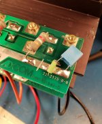
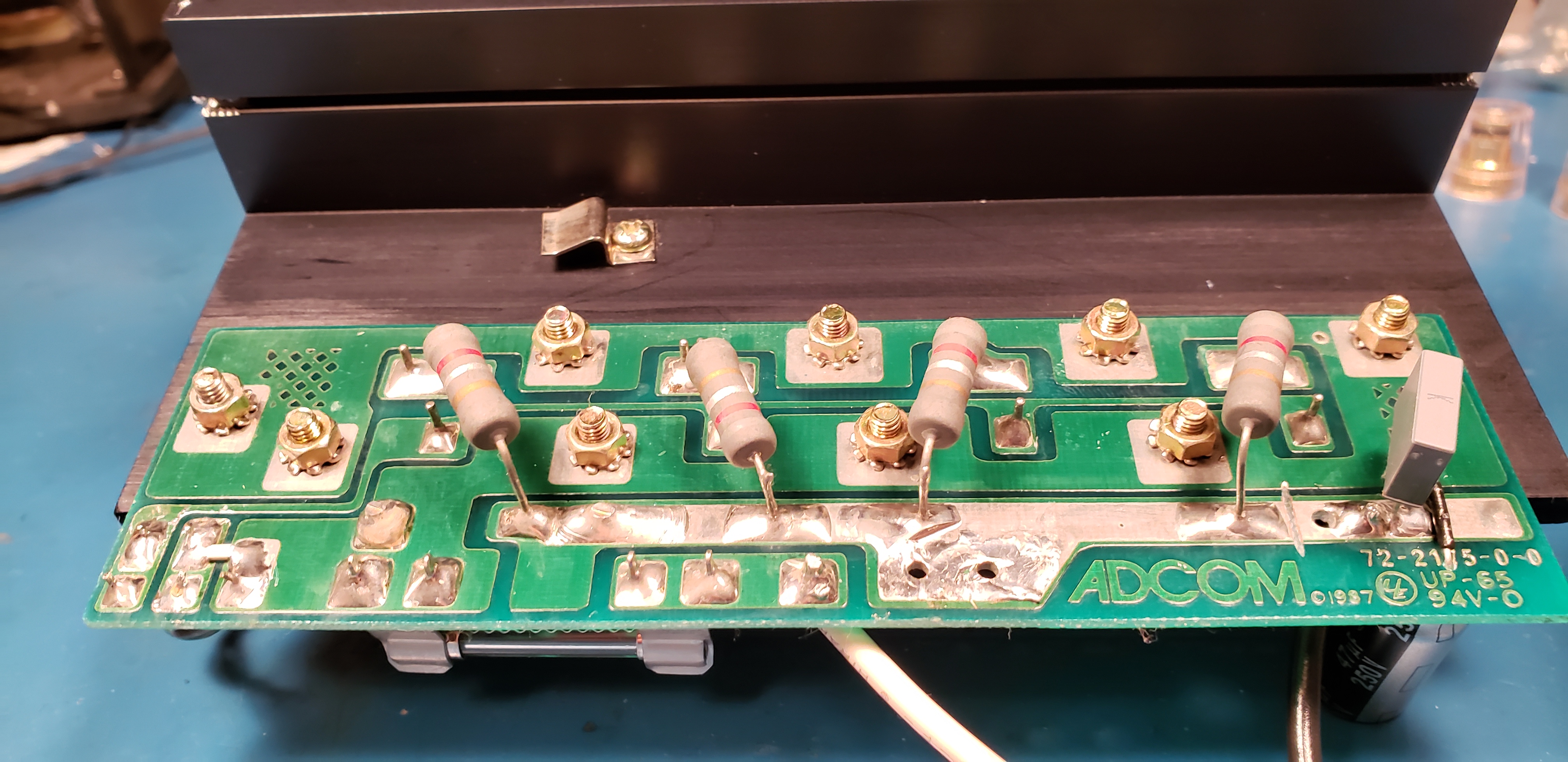
adcom Bypass cap installation on output PCB
Someone commented on this photo by Hoppes' Brain a while ago about a way to install bypass caps on the Adcom GFA-555 output PCB. They wanted to know what the connections looked like on the other side of the board. Does anyone have a picture , I'm curious myself , thanks
Someone commented on this photo by Hoppes' Brain a while ago about a way to install bypass caps on the Adcom GFA-555 output PCB. They wanted to know what the connections looked like on the other side of the board. Does anyone have a picture , I'm curious myself , thanks
Attachments
Tape on transistor legs causes all sorts of problems.
I soldered in a transistor from a bandalier tape and it didnt work.
Took a while to find the problem but a part of the bandalier tape was left on a transistor leg and was preventing it making a good solder joint.
I take more care now with tape and make sure it is all removed before soldering.
I havent seen shorting tape on transistors before. I guess its to protect them from static ?
I re-installed the original transistors and the DC offset is now @9mv. Interesting , even though the transistors tested Ok , they obviously did not perform under real world conditions. Thanks for the suggestion to go back to the original working part in order to troubleshoot the problem, the fundamentals, tend to work ....
The copper foil tape is meant to keep both transistors at exactly the same temperature. Hfe and Vbe are highly variable with temperature.
Here's more detail on that bypass capacitor connection. There is a little extra PCB trace on the end of the trace that connects all the emitter resistors. I make a cut to isolate it, and then use it as a ground connection for the capacitors and the wire that connects them back to star. I put a piece of insulation over on of the capacitor legs so it can reach across the trace without shorting. Just make sure you get those polarities right. The picture shows the PNP (negative) side, so the negative lead of the capacitor connects to the negative trace where the collectors connect, and the positive lead goes to the new ground connection.

Here's more detail on that bypass capacitor connection. There is a little extra PCB trace on the end of the trace that connects all the emitter resistors. I make a cut to isolate it, and then use it as a ground connection for the capacitors and the wire that connects them back to star. I put a piece of insulation over on of the capacitor legs so it can reach across the trace without shorting. Just make sure you get those polarities right. The picture shows the PNP (negative) side, so the negative lead of the capacitor connects to the negative trace where the collectors connect, and the positive lead goes to the new ground connection.
According to the Adcom manual bias is adjusted with no input, does that mean input shorted or open ?. I am getting 28mv between negative speaker output and emitter resistors at best when adjusting P1 , but can get 16 mv or less with input shorted
Input shorted is guaranteed no input, however......
You should be measuring ACROSS (any of) the emitter resistor, not one probe at the neg speaker terminal !!
- Home
- Amplifiers
- Solid State
- Adcom GFA-555MK1 input transistor, dc offset problems