DEQ2496 repair/replace ? Anyone have a circuit ?

Since about 2004 a Behringer DEQ2496 has been a central device in my stereo providing overall EQ in the analogue "processor loop" of the amplifier.

Although I do make use of some of the other features on occasion (like the excellent stereo width processor) I primarily use it for its PEQ features for room mode correction, and while I'm actively doing speaker development I use the PEQ and GEQ modes for temporary correction while working with crossovers etc.

It's outlived an amplifier and some of my previous speakers and is still in daily use, however it's starting to show it's age a little and I have had a few problems with it over the years.

When it was only a few years old the power supply blew up but that turned out to be a loose screw that shorted out on one of the power rails and blew a couple of diodes in the power supply - since repairing that it has only had one other fault in 17 years until now, and that is the bypass relays for the analogue inputs/outputs have been problematic.

About 6 years ago I started to notice that the output level on the right channel was intermittently down a little on the left channel - enough that I could notice a stereo imbalance, something on the order of 1dB.

Usually flicking it into bypass mode and back (switching the bypass relays a few times) would fix it but it would return a few days/weeks later.

Eventually after concluding the relay contacts were faulty in one relay (and only in the engaged mode, not the bypass mode) I replaced the bypass relays with new good quality relays and all seemed well for a few years - the intermittent shift in stereo balance between the two channels stopped happening.

In the last year I noticed things were not right with the stereo balance again and after doing some careful measurements with ARTA between left and right channels I've noticed there is now a 1.5dB error between the channels with the right channel having a lower output than left once again.

However this time it doesn't seem to be the relays as they are still relatively new and switching the relays in and out makes no difference like it used to with the old ones.

Further, there is a difference in frequency response between the two channels - the bad (right) channel has noticeable low frequency roll off such that at treble frequencies the right channel is down about 1.2 dB, in the midrange about 1.5dB and in the bass down around 1.8dB.

In analogue bypass mode both channels are identical.

This suggests the problem could be coupling capacitors between the DAC and the signal path to the relays which have lost a lot of capacitance. I had a very similar problem with my previous amplifier where the miniature electrolytic/tantalum (can't remember which) coupling caps in certain stages of the pre-amplifiers started going faulty causing loss in signal level in one channel and a slightly sloping up frequency response, so very similar symptoms to what I'm seeing here.

However with a surface mount design and no circuit diagram it's hard to tell where the coupling caps might be, what value they might be or whether it even has any for that matter.

So has anyone done any modifications/repairs to the analogue stages of the DEQ2496 (mine is a Revision 1 running firmware 1.4 not the later revision 2) or have a circuit diagram for the analogue stages that would help me troubleshoot this a bit further ?

Unfortunately I don't have a good working scope at the moment which makes it quite a bit harder for me to troubleshoot this sort of problem, although I could do some measurement with my ARTA setup.

As a workaround I've had to put the device in dual mono mode so I can increase the gain on the right channel and also slightly tweak the frequency response however I'm not very happy about this as it makes adjusting the PEQ's less convenient and I can't get an exact frequency response match between channels.

As it's getting long in the tooth now can anyone suggest any other units that don't cost a fortune that have comparable functionality to the DEQ2496 ? I'm still very happy with it if this level imbalance problem didn't exist, so am I better to just try to repair it again ?

Some of the EQ systems that I've seen people using aren't nearly as flexible in terms of user interface and functionality as the DEQ2496, surprising given how old it is now. So I'm not even sure what there is available today that's comparable in functionality yet affordable.

I've certainly had my money's worth out of it over 17 years!

cheap Chokes in Europe

Hi,


Is someone knowing where I can find cheap chokes in Europe. I need for the power supply of a tube circuit a 2x10uH choke to smooth the B+ power supply rails made with a simple solid-
state bridge rectifier (no tube rectifier). I find the hammond, Lundhal to be too much expensive those days and knew Mapplin used to sell cheap but good enough ones.


Anyone aware of a good cheap shop in EC?


Many thanks

Marantz PM 310 low volume

Hello.
Marantz PM 310 low volume output...
50%.....
The sound is very good,no distortion .
Bias ok,11mV.
All voltages are OK.
33V....-33V...15V.....-33V.... OK
No blown fuses...No damaged parts.
Amplifier works fine but volume is 40....50 % lowest.
If I activate loudness knob no change.


SM

https://www.google.com/url?sa=t&sou...QQFnoECAUQAQ&usg=AOvVaw1x4QOCQl2EhUSCBuZ9FiRc

SPDIF format identification using microcontroller

Hello all,

I have a requirement wherein I may have to identify (not decode) the compressed audio format (AC3/DTS/MPEG etc.) carried by an SPDIF bitstream, using a PIC microcontroller.

Assuming that a phase-locked synchronous clock signal is already available to the microcontroller, how would one possibly go about doing the above? The MCU clock is at 64MHz and interrupt inputs are available.

Thanks in advance.

Zen Choices for 100v PS

I read though much of the Zen articles on FirstWatt but didn't really find what I was looking for, and I searched around a bit on the forums, but still came up lacking.


A few years ago I built the delux version of the De Lite amp using a 100v power supply and now I want to build another amp that can use that same supply. My main criteria, besides running on the 100v, is that I can get an PCB for it (even if I send files to a board maker) and it'll run 4 ohm speakers (which I have several of). I am still kind of a novice builder and haven't yet finished a BA3(just need to finish wiring it). I like exotic things though and was hoping another Zen amp would be compatible with my requirements....any suggestions? Maybe the PS can power two bridged channels of something at a lower voltage?


Worst case scenario, maybe I can still use that 800VA 75VAC transformer and modify the rest of the supply for something else that fits the above criteria?

Horn/waveguide flare termination

For a given amount of "extra width", what is the most optimal/efficient profile for the termination of a horn or waveguide mouth? Obviously looking to minimize on- & off-axis aberrations and other diffraction effects.

I think it was mentioned somewhere that a plain radius would not be best, but rather something more like an Euler spiral with a smoother derivative curve.

And would it make any difference, profile-wise, if the mouth were terminated into a flat baffle vs free-standing and needing a wraparound?

Fender GT100 and GTX7 Footswitch Problems

After contacting Fender tech support and having no success I thought I might see if you good folks have any suggestions.
I upgraded my Mustang GT100 MGT4 footswitch (which worked flawlessly) to the GTX7 footswitch that Fender advertises as compatible with my amp. The only way I can get it to function properly is to plug the GTX7 into the amp AFTER the amp has been powered up. Do you think this means that the voltage drops to the footswitch amp circuit during amp powerup? It's not the end of the world but I would appreciate any advice. This issue has been posted to Youtube and Fender forums by other GT100 owners. Thanks

Tuning crossover, trying to dial in plucked strings

Hi All, I've printed a waveguide using Augerpro's model: Waveguides | somasonus

Now I have constructed a box with a Dayton RS225-4 and an RST28a and after some measurement and tweaking it's sounding fairly good. I'm targeting a flat on-axis response with a goal of 6db drop from 100hz-20khz in-room at the listening position. A 1.5khz 4th order crossover in the MiniDSP 2x4HD with a few parametric cuts per driver has got me there and voices are sounding good.

At this point it sounds like I'm more than halfway to where I want to be, but at the moment I'm hearing a bit less 'attack' and 'clarity' than I'd like to hear. As an example, the plucked strings in Hotel California aren't quite as distinctly separated as I've heard on the best speakers and headphones I've heard it on.

Dear knowledgeable DIY Audio forum participants, where do I look next? Can the tonality seem about right (voices sound pretty good) and have a problem with this if I haven't got the phase just right? Or is it likely to be a problem that can be fixed with EQ?

I'll post whatever measurements might be helpful. Thanks for any advice!

Cabinet Veneer Techniques

I’ve built 3 different cabinets at this point, and my woodworking and equipment keeps getting better every year. My first was an MLTL a long time ago that was garbage, then I built a Dallas II that was - fine, and then I built a Pensil for my 10p and they turned out pretty good. Since then I’ve built a few pieces of solid wood furniture I managed to sell during COVID and I’m ready to turn the skills I’ve learned into a new set of cabinets. Considering the FHXL.

This time I want to lay a nice veneer down on the Baltic birch and was hoping for some pointers.

Generally I like to round over my corners to make the design look a little more finished and to take a little “weight” out of the design - but I’ve only ever done solid wood construction, and I’m wondering what the best way to deal with those rounded corners is if I wanted to add veneers.

I was considering painting the cabinets black, and leaving the black detail as part of the round over corners, while only veneering the straight parts of the panel. This would frame the wood veneer a bit.

Can anyone show me some designs they’ve done and what they prefer? I worry that veneering over the round over won’t look right, as a “real” round - over will reveal the grain in a different way than looking at it head on. I also worry that the black “framing” will look too rustic or unfinished.

I know you all on here have probably done a bunch of great stuff, so hoping someone can show me what’s up.

Pic of the last consoles i did to hopefully prove I’m not all thumbs, and to show you more or less how I design the stuff in my house. 🙂

DFD26CD5-D726-4251-8763-C80D8739563E.jpeg

58334259-076A-4F93-A45C-562EC84DE42D.jpeg

Simplified MrEvil / PMI Capacitance Multiplier

Based on the work of MrEvil and the alterations by PMI I would like to submit a simplified version of the capacitance multiplier circuit. I had suggested in another thread such a circuit would be an opportunity to incorporate the ability to cut-off the pass transistors during a fault condition and rather than pollute that thread It seemed appropriate to create this one.

Attached is the basis for the design of the capacitance multiplier, the shutdown circuit has not been decided upon yet. I'm thinking of using a simple two transistor latch to pull Q1 and Q4 base connections to ground when a fault event is detected. My initial notion is to use such facility in place of a relay on the amplifier output line for DC protection, but other possibilities exist like a low power standby mode, or shutting down for other faults like over temperature etc.

Ignore my choices for M1 and M2, these will likely end up being Fairchild FQP47P06 and FQP50N06 or similar low RDSon devices.

Any comments or ideas?

Attachments

  • Capacitance Multiplierv2.asc8.png
    Capacitance Multiplierv2.asc8.png
    41 KB · Views: 6,615

what disc drive should I get?

I have a few boxes of CDs to upload, it is worth paying a couple hundred dollars more for a drive like this Asus? https://www.bestbuy.ca/en-ca/produc...6d1x-u-external-blu-ray-writer-black/10756372

Of course reliability is a consideration, as equally so is the sound. I'm after one that's accurate that adds the least amount of colouration. Can I get away with a $59 job or is it worth spending a couple hundred on one? Something like the Asus I linked back there perhaps?

Steinberg UR44C: Review

I bought this USB3 soundcard to make measurements on various things, so... it's review time.
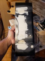
Unboxing

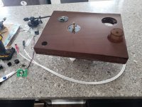
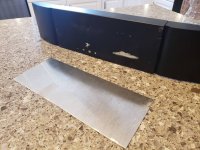
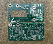
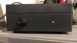
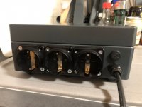
It looks nice and heavy, all metal case, quite flattering and robust. If you drop it, make sure it lands on the back, as they designed in a nice flange to protect the connectors. There is the same flange on the front, but it is too short to protect the knobs.

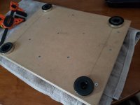
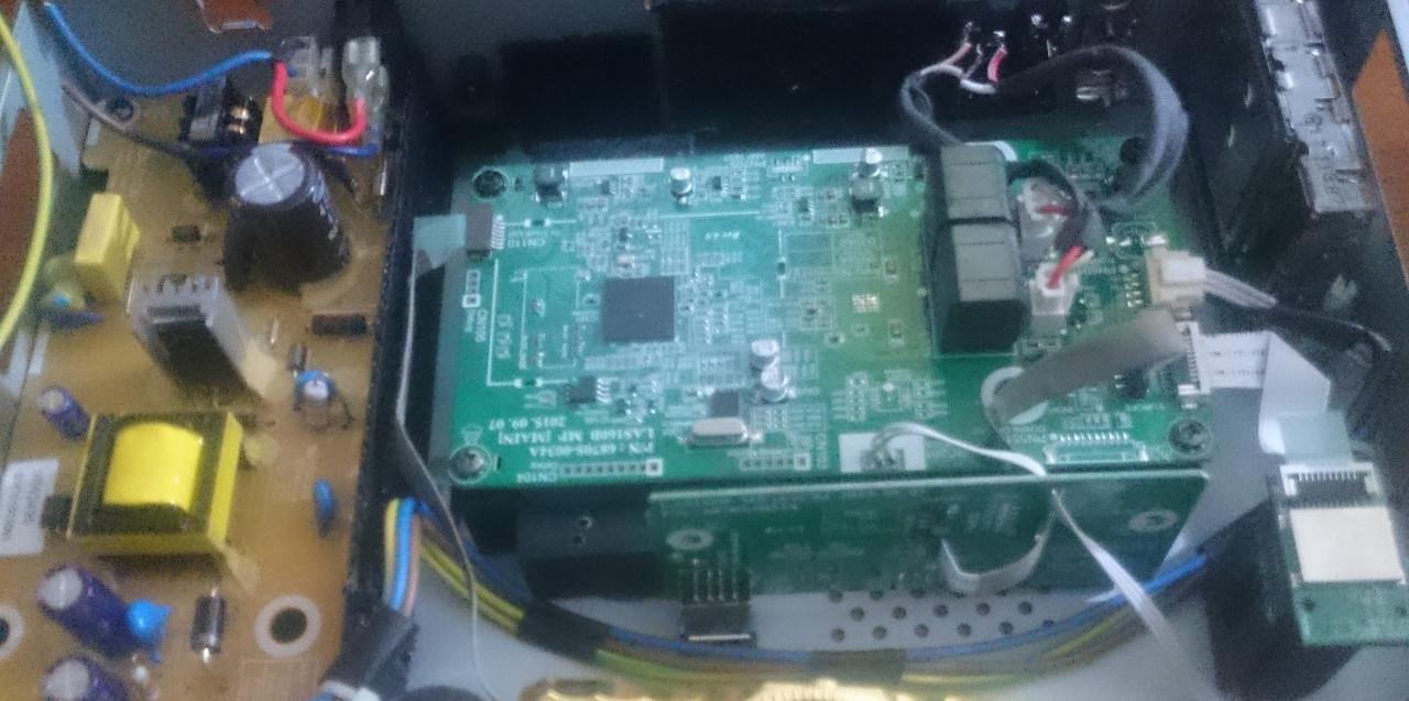
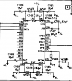
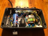
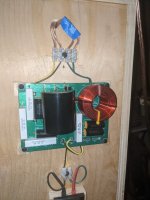
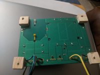
It is easy to open, just 4 screws.

Software installation and overall user experience

As tradition requires, the firmware updater crashed mid-update, bricking the device. Fortunately, the embedded guys at Steinberg are smart, so the embedded bootloader was still running and eager to load working code into its flash.

However, the PC software was written by idiots. The updater proudly displayed that the device had the latest firmware installed, and did not need to be updated. Noticeably, it lacked an "UPDATE IT ANYWAY FFS" button. Who needs to verify the checksum to make sure it is properly flashed? Just check the version byte and tada! done.

Customer support does not exist.

So I loaded the firmware upgrade app in the debugger, stepped through the asm code, found the place where it got the version number from the device, decremented the last digit in the memory dump, and hit "RUN". The idiot software was very happy to inform me that the device had the firmware version number I had just typed, and that it would update it.

It was a bit more complicated than this, but I'll spare you the details. I don't know why a firmware updater needs 15 threads and 2 state machines in 2 different threads to process sending and receiving USB messages, though. Mystery.

This time, it worked, and it unbricked itself.

The ASIO drivers are solid, no crash or bluescreen, which is worthy of notice.

Yamaha is very proud of their reverb (it does sound nice), and the PC software is written by idiots, so you have to look into google to find out how to disable the reverb, then find out for yourself. It has to be disabled in both mix busses, and the DAW has to be set to "solo", otherwise the inputs feed through into the outputs, which is what it's supposed to do if you're recording live and want to hear yourself playing.

Anyway.

USB port

It has a USB 3.1 type C port so it can power itself from a PC with a USB-C port. It also has a wall wart if you don't have a USB-C port. That's nice. It doesn't use the USB3 throughput, so it works fine on USB2, with the wall wart.

It doesn't work on Linux.

4 line outputs on 6.35 jacks

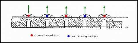
They are balanced, in the sense that they output a positive and negative signal:

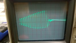
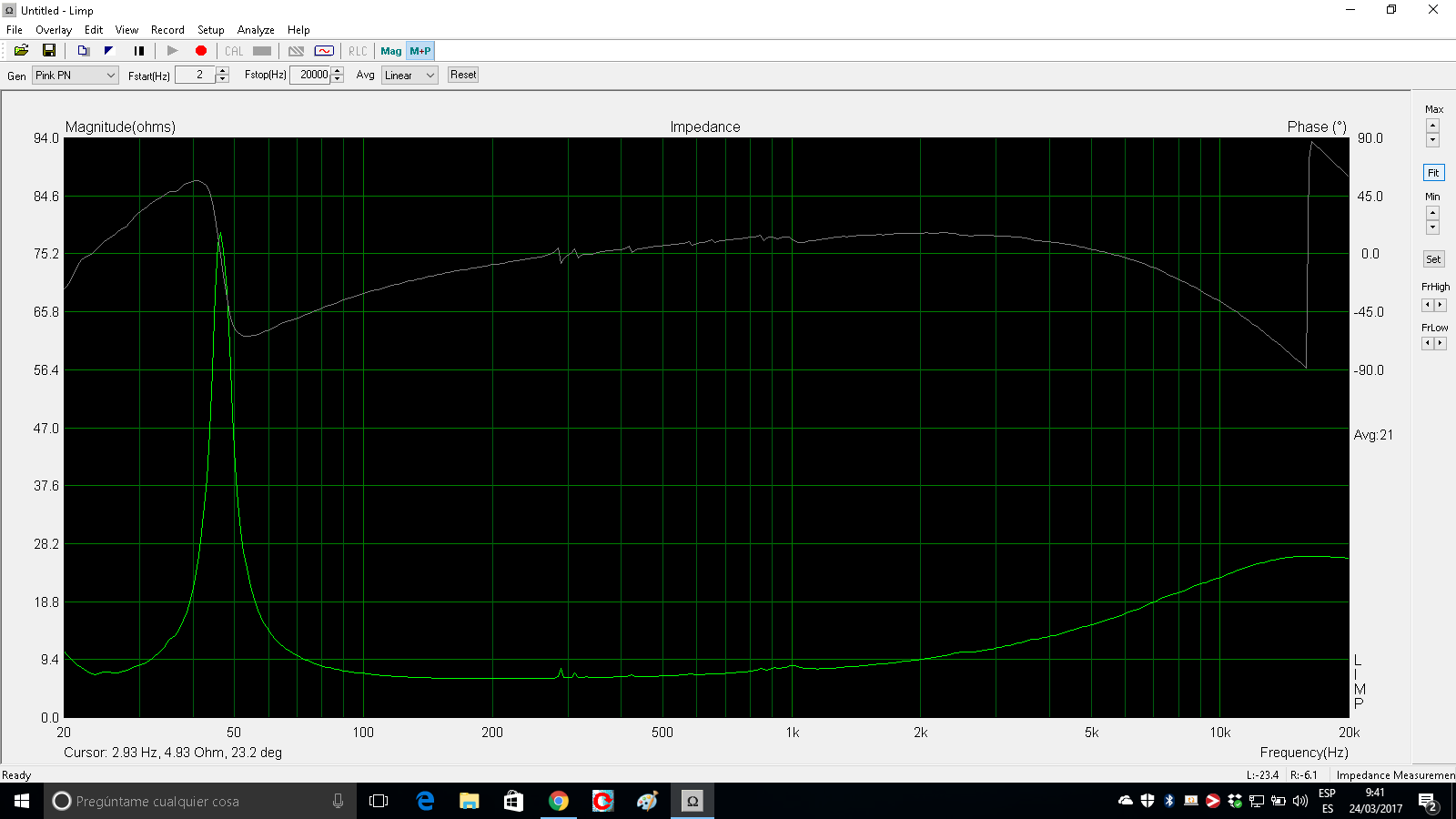
Full scale digital output, 6.32 Vpp on the tip, 8.64 Vpp on the sleeve, so you get a bit extra signal for free.

FS output balanced.png

When either the tip or the sleeve is shorted, it does not distort, as some balanced drivers sometimes do. Instead it doubles the output on the other polarity, which is nice, and of course it clips hard.

FS output tip shorted.png

So you have to halve the level in software, for example to 0.45 full scale instead of 1. There is no analog gain control. Anyway, the outputs work.

0.45 output tip shorted.png

2 "main outputs" line outputs on 6.35 jacks, with volume pot, same signal goes to 2 headphone jacks, each with volume control.

These output the mix bus, so the PC can't use them as outputs. Even though it can, because it does, and the interface declares itself as 6 channel, but if you try to output a signal on them, it doesn't work. 4 outputs are fine, I don't need 6, so this is a problem for another day.

Loth X Polaris speakers for sale

I have a pair of Polaris in good condition but not mint. The Stamm drivers were blown by a power surge from our friendly electric utility company. I still have them. I replaced the Stamms with SEAS. The speakers are VERY big and I have a small living room. Someone must be out there with the desire to try different drivers or who wants these beautiful horn driver speakers. They were something like $8k retail new. Will sell for $1850 plus freight. They are currently in their large wooden crates ready to ship.
Loth-x Polaris [English]
Contact Conrad 208.720.2100

Need help...could make you some lunch money

I have tried unsuccessfully to make an amplifier for my boat. I have used a couple of single board amps (XH-643 and LM386 off amazon) but the noise is just to great. Maybe the amp needs shielding..I don't know, but I do know I need help. As a 61 yo male I am no damsel, but I am in distress 😎.

My email is brianbeyyoung@yahoo.ca if you want to talk about my requirements.

Heatsinks with a "lip" for mounting components?

What I'm trying to achieve is essentially the same concept as the way transistors are mounted on the external heatsinks in most amp cases. However, I want to use a smaller heatsink, mounted internally. This would be instead of the heatsink and transistor being mounted referenced to the PCB. The intent being to be able to use a larger heatsink and have the heatsink and transistor securely mounted to the case.

Trouble is, I can't find generic heatsinks with this sort of "lip" for mounting. I'm sure I could modify a traditional full-finned heatsink, but I'd worry about not getting a smooth mounting surface.

Does this sort of design have a name?

Attachments

  • Untitled 2.png
    Untitled 2.png
    24.3 KB · Views: 145

Will Sabre ES9018 ever be beaten?

I run three DACs in my system.

The Sabre ES9018 is found in SMSL superb little M100 and is dedicated to my subwoofer. The Sabre ES9038 is in Toppings D10S. It's supposed to be the improved version of ES9018 but I don't like the sound from ES9038 and I've heard distortion which makes it untrustworthy. I use this DAC just to convert USB to Toslink bypassing the actual DAC function.

The Wolfson WM8742 is in Cambridge Audio's DacMagic 100 and this runs my full range speakers.

Out of these three Sabre ES9018 has the best sound, which is strange because it's my least expensive component 😱

Agreements or disagreements? How do Burr Brown chips sound?

Fluantz project completed!

Guess I forgot to post about this project from last winter, as when spring hits, there's tons of outside projects and toys to do and play with! Now that cold and rain is here, its back indoors, and back into audio bliss.....
This was a simple (as im a rookie) diy project of taking my first and only TT, moding it, and making it my own. This was given to me from my mother 3 years ago as I've always wanted to hear what vinyl is all about. As she's getting up there in age, I wanted a easy project that the two of us could do together, improve the sound a little, and make it a "permanent im not going to get another and replace this one with something better" turntable.
I love the look of my marantz gear, and thought, why don't I make my fluance rt-81, match my marantz stack?!
So, I tore apart the fluance, and took my set of decent patch cables, and bypassed the internal amp 100% (even though there's a defeat switch, it still runs the circuit through a series of resistors) and soldered directly to the tonearm wiring, also redid the grounding wiring as it was poorly done and measured high resistance. I then sourced a marantz face plate in the right dimensions and a set of feet for my project. At first I filled in all the holes with a 2 part plastic jb weld epoxy, this left, well, a rough finish, so on went the bondo, and after much sanding, and filing, and sanding, the surface was still not 100% flat, and tried the black brushed aluminum vinyl wrap, and looked horrible.
Back to the drawing board....well, got a piece of aluminum plate from Lowes, cut, sanded to correct size, wrapped with ...the....well, wrap, and looks great! Smooth, flat, factory.....ish hahaha.
Another mod I've always seen is to isolate the table. So, again, ebay and grabbed some half inch sorbethane washers x4, left the bottom cover off the fluance, and placed the washers between that and a baseboard I made out of 3 glued and screwed layers of half inch MDF, slightly wider as this base would be used to hold the front marantz panel. I installed some 1/4-20 thread inserts into the base, as I wanted the feet to be adjustable for leveling the turntable (as the stock rt-81 didn't have adjustable feet). Installed some same thread screws into the marantz feet and installed after the wrapped board, attached the front panel (after more sanding and painting) reassembled the rt-81 and placed back on top. I still need to do some finishing of white decals for the model number ( Marantz TT-81? Or TT-1950 as this was the year my mom was born?) I also changed out the cart to the ATVM95ML after many recommendations.
Results? Well, I can tell you for certain the curtain has been lifted to reveal what my "reference" system can do for high frequency, it was as though before anything over 14k hz was cut (as I have a seperate headshell for the stock cart, I can A/B them) and believe this was due to the rewire job. I also noticed that mid bass around 250 hz tightened up as the kick drum in fleetwood make "second hand news" tightened up, I believe to be attributed to the isolated base. Now, as far as the cartridge goes.....yeah, that kick drum? I can now hear definition in the thwack of that mallet? Hitting that kick drum, separation is also increased for as busy as that song is, it never gets blury or obscured with the "precision chaos".....
But above all else, I got to build something with my mother by my side, something that can't be bought, and a permanent piece to my entertainment system that won't be traded in at any time ]20210213_193227.jpg20210213_194100.jpg20210217_070727.jpg

Attachments

  • 20210123_131144.jpg
    20210123_131144.jpg
    123.5 KB · Views: 164
  • 20210123_153400.jpg
    20210123_153400.jpg
    66.9 KB · Views: 174
  • 20210213_080648.jpg
    20210213_080648.jpg
    112.2 KB · Views: 187
  • 20210213_080713.jpg
    20210213_080713.jpg
    59.7 KB · Views: 180

Harmon Kardon 930 receiver weak left channel

My HK 930 has worked well for a long time but recently the left channel has gotten very weak. I have to turn the balance control about 3/4 to 7/8 turn to the left to equalize channel volume. I'm not an electronics pro but am willing to take a stab at tracking down the problem if it's not way too involved. Anyone have suggestions?
Thanks!

Realistic MPA-100 Model#32-2023

When I got this delivered I plugged it up and got nothing but the power light. So, I cracked it open and started poking around. First off I found signs of overheating on the preamp board along with a resistor that was disconnected on one side. I started taking the board loose so I could examine it better. I disconnected 4 wires. Stopped, and when I started again a week later I forgot which wires I took off from which post.... So now I am stuck. I can't even find the service manual to buy it, let alone find one to download. I'll work on that. When I got the board loose enough to flip it looked terrible. I'll definitely have to clean and re-solder it before I re-apply power to it. I didn't see any burnt traces though. Just a lot of corrosion. I am going to replace the two resistors where it looks burnt. That's all I think it might need. If any one has any schematics or knowledge of this amp I would appreciate the input.

Cheers!

Chip regulators vs capacitance multiplier

Having done some experiments with different chip regulators in an effort to get a real good S/N ratio, I've concluded none of them do a very good job at attenuating ripple.
There's a really effective and simple solution, ie, the capacitance multiplier, which is a glorified name for a transistor in the emitter follower configuration whose base is fed with an R from the rail and filtered by a C to ground. The collector connects to the rail and the emitter is the output.
Yes, there is some dropout V and subsequent power dissipation that make it inappropriate for a whole system but nonetheless, as a power supply rail buffer for a preamp section, it's way more effective than a regulator. If you are worried about the 2 volts of dropout, increase the rail V.
It's so effective I no longer regulate a bipolar power supply for a preamp/power supply.
Thoughts?

Help me choose a fullrange speaker

Hello people! I am planning on changing my speakers for a full range speaker setup.

I listen:
80% of time jazz (hard bop, bee bop, soul jazz, some vocal).
20% 70's, 80's rock, country rock.

My amplifier is a Single Ended KT88 tube amp. Approx. 3W RMS per channel.
I don't listen music very loud.

My current speakers are Monitor Audio Bronze BX2 (2011 series)
Specs says 90 db SPL efficient but can't really assure that.
I also have a Monitor Audio Silver W12 subwoofer.

My living room is like attached drawing.

I like my speakers but I really would like to get better detail and if I can, more volume using more efficient speakers,
so I can turn the amp volume down a little.
I thought about MarkAudio Alpair12p or perhaps a Fostex.
Would you suggest any?
Thanks!

Attachments

  • Sin título.png
    Sin título.png
    8.6 KB · Views: 407

Assistance with Satori 2 way build

I built a 2 way (WWT) using Satori MW16P-8 and TN29R. I have tried several crossover configurations. There is one thing that is bothering me is that the speakers sound forward. Not necessarily shouty but definitely too forward sounding. I dont want to prejudice any responses so that is why I have not attached any crossover files. I am wondering if there is a certain sound characteristic of these drivers that makes them sound this way. I would say that the region that I am concerned with is 400-1000 hz. (estimating). Would love a discussion to fix this. (BTW I am using XSIM to model this)

SSE build - power measurements

Hello everyone,


I have build my SSE with Hammond 274BX power transformer, 193J Choke and 1628SEA output transformers.


The board was very straightforward to stuff and assemble. Many thanks to George for his effort in the design of the SSE amp.


I have taken some measurements and the power numbers seem kind of low.

With new production (New Sensor Svetlana) KT88 and the following parameters:


B+ voltage: 442V
plate voltage: 430V

Voltage drop across cathode resistor (560 Ohms): 42V
Plate dissipation: ~30Watts


Using 8ohm dummy load resistors, I get ~1.5W of power in both UL and triode mode. The strange thing is that I can actually hear the 1khz test signal through the amp.

The amp sounds great otherwise.


KT-88-triode.png - Google Drive


KT-88-UL.png - Google Drive


Are these numbers in line with other builds?


view

KEF Reference series 103/2 speakers

$540 prefer local pickup in Pacific Northwest. Can split cost of shipping.

KEF 103/2 Reference series from the 1980s. Still in very good/excellent condition.

These are excellent studio monitors that present very natural presentation, very balanced from highs to lows in 50s. Being sealed, can work well near wall.

Can provide pictures if interested. Selling replaced with Proac Response 2s.

MLTL driver placement and usefullness?

Hi.

I was going to build ported towers for my 2x Tangband W6-658A mids, but came across the MLTL design.

I'm still not a pro with Hornresp, but I can functionally use it pretty well.
I used the input wizard to make a mass loaded transmission line and put in 2 of those mids, and the default settings already looked very good. The default was 58l big and my ported optimum size was 50l so not that far.

I was wondering how the placement of the drivers affects the end result. As this is an offset-driver design, where the driver should be placed right, to cancel the first peak in the response.

I haven't decided between an MTM or 2.5-way design yet, so I might just put the tiny tweeter in between the mids, to be able to test both scenarios myself, as the tweeter is only 54mm wide (pre-designed crossoverpoint is 2.8kHz as the tweeter Fs is 1.4kHs as seen in the impedance graph)

If the drivers shouldn't be that far from each other vertically, should I place them next to each other, with the tweeter on top, in the valley between?

Then, should the port be facing the front, back or down? And will I get more output with MLTL than ported? I have 120Wrms @8 Ohms and 170Wrms@ Ohms on tap.

Too small?......

So, its that time of the year again, with the cold and rain setting in, and eventually snow, I put away all the toys for storage in my pole barn and am heading back inside for winter hobbies. Last weekend I started gutting the basement (unfinished wall studding in the center, some drywall, rough flooring etc) and ripping down the insulation in-between the floor joists. The amount of mouse .....eh.....stuff is just unbelievable! (Went all around inside and out and sealed everything up). So, what im getting at is there's a room, probably built 30 years ago when the house was built, its 12 feet long, 8 feet wide, and 7 feet tall (these would be finished dimensions) walls A and B are concrete blocks, C is studed with 1/4 inch plywood, and D is plywood with no studs. My goal is to get into DIY audio, experiment with building small (3-7 inch driver bookshelf speakers) and building my own amps, tube and solid, starting out with cheap beginner kits and working my way up, and have plans for a diy turntable. I'd be in a recliner , speakers on stands 5-6 feet out, a diy powered 8 inch? Sub, and behind them would be shelving with all my diy and a few already made speakers I could rotate out and play with, in between the two shelves would be the equipment rack with multiple sources, dacs, tuners, amps, turntable preamps etc that can be swapped and played with. Is this area too small? I ask because if I keep it, I'd brace wall D, spray foam everything except the floor, then.....well, I'm not sure, would putting up drywall over the spray foam only to do acoustic treatment make any sense? Or do I forget about that room, rip down the walls and build bigger? Again, this would be for a diy bookshelf collection I plan to start building with my mother to spend as much time with her as possible before she leaves this world, and to see what a ribbon tweeter sounds like vs titanium, or tube vs. Solid, preamp vs amp. As it would be small, id like to think I can get by with a few quality watts (cheaper) then needing massive power. My reference system in the entertainment room, when cranked, in the seat, using a app, reaches 85 db peaks at 8 ft from the speakers, so, honestly don't think im looking for 90+ as it would likely become painful (as well as possibly permanent) FWIW I have been searching, but everything shows up higher ceilings, and no mention of sprayfoaming the surfaces. As always, I look unto the people for advice, guidance, suggestions, and ideas!

Tang band w-1772 in a rear loaded cabinet

Here is my attempt at making my first set of speakers

View attachment 1001737

View attachment 1001738

View attachment 1001739

1m height x 30cm wide and 80cm deep.

this was a huge effort for me, as I had no wood working skills when I started this project.

The Lecleach Horn on the top is not wired up this time.
I am still figuring out what compression driver to use.
and I did not make it, its milled from teak wood. it was previously used with my 15 Inch eminence cabinet with a 1 inch eminence compression driver.

now only playing full range.

its driven by a pair of Amp Camp amps in Bridged mono mode.

The pre-amp is a modified version of BOZ amp, thanks to boards supplied by Gareth from Sydney (I think he is on this forum).

right now, its connected to TV using optical out / DAC, makes it easier to get some hours to burn-in

so far, far far exceeded my expectations. its got a very livery presentation.

I cant even go more than 30% on the volume knob, its LOUD.

old and new school of output transformer winding

Anyone would like to share about the differences in sounding between old and new school output transformers winding? As for the winding works,old school method is complicated where you need to put winding in layers and sections while new school you can easily change a primary or secondary section becos the winding is not overlap each others, so is easlier to play around cos the are seperated from each others. correct me if i am wrong. but what about sounding? leaking capacitance?

Sound Bar Hacks and case mods

Hi all,


I made some contributions in a projector thread about understanding the protocols for lamp ballast communication. This is a pretty great community. I'm not a sound engineer, so I might be wrong and looking for input.

I am building an amp from the guts of a soundbar LG LAS160B.

This is going to be detailed, so please don't be deterred by the length of the post. There is a photo and the details are there to spare people's time.

https://postimg.cc/9w5HHqX6


Background:
I was not happy with the casing of my sound bar as it seemed to be deteriorating. So I salvaged the guts of it for use later. The sound used to reach about 85-89dB at max volume, subjectively from 3m away or 10ft indoors. Never really got loud enough to enjoy much and seriously lacking in bass and a lot of compression past 12kHz although I could hear some 14kHz come through.

The old specs:
There was one rectangular "racetrack" full-range driver per channel in this 2.0 system 40mm x 100mm or 1 1/2" x 4". There were places for tweeters to go in and online tear-downs had tweeters, but mine came without any and there was nowhere to plug them in and no crossovers, although a lot of empty room in the driver compartments.

  • SPL: 81 dB
  • Bass Reflex (but there were no ports for this or passive resonators)
  • Impedance: 4 Ohms (actually this was measured off-state resistance but quoted as impedance)
  • Unshielded.
  • 25 + 25 W Amp.
  • 14.5V SMPS at about 5A.


My thinking:

The first watt of power is the most important. I felt like LG did something amazing with their DSP and enclosure to manage to get the range they did out of these little speakers. I think the excursion was pretty high. I wanted to test my theory for myself and others. I play guitar a bit and close to a lot of musicians, so I kinda lamented the sound experience with TVs. Like we gave up on a century of speaker development to have these sleek bars. They sure look good and can be good if you get really expensive ones with a ton of engineering in them. But fighting against physics is hard. So my idea was to use some bookshelf speakers with the amplifier only of the sound bar and have the niceties of bluetooth when I'm lazy and optical in etc for permanent connections.

So I only need 1W of power to get 81 dB of sound right at 1m? Didn't feel like it at all. But I went with the stated numbers. 25W per channel of output power suggests about 14 dB of gain. This should bring up the volume to 95dB. Listening from 10 feet away drops this by say 9 dB but there was 3 dB of room gain, so a final 89dB. This is what I think I was hearing so I thought I could keep running with these numbers. So I just had to build it out into a nice chassis and choose some speakers to go with it was my hope.

New (to me) speakers:
Since this is a test setup, I wanted to try it on some speakers I'm not too attached to. I gave away my Panasonic SA-PM25 speakers years before, but they were pretty ok. Nvm. I found some cheap old Sony SS-CMD373 speakers x2 on eBay for the test. They were not damaged and the resistance matched the stated impedances. I know impedance and resistance are not the same thing.

Each one is/has:

  • 5 1/4" Woofer
  • 1" Tweeter
  • Impedance: 6 ohms
  • SPL: 91dB is my estimate based on comparing 3 driver specs of the same type and averaging. Crude, but not a bad starting guess. The Panasonic speakers I gave away had 86dB and were 1" smaller drivers. For the purpose of calculating I guess we could estimate it to be 88dB at the low end.
  • Frequency response about 40 Hz - 20kHz comparing it by ear to other speakers I have. Maybe goes a little lower. My phone app SPL meter shows activity around 30Hz but low amplitude.


Calculations:
So, for these new speakers with the LG Amp, the first watt should get me say 88dB at 1 m.
The gain of the amp should be 14dB as before at full volume, but scaled due to impedance difference.
Since the impedance scaling is a factor of 4 ohms / 6 ohms, the power into 6 ohms would now be 25 x 4/6 = 16.7W.
This is worth 12dB.
So at full volume at 1m distance, the volume should be 100dB.
Making adjustments for the 3m listening distance and room gain brings this to 94dB.

Did it work?
Sure it makes a sound. The bass was ridiculously high at low volume on the remote. I had to eq -12 dB on the bass band of 60-100Hz on my android eq. That and add about 4 dB to each of the other bands brought it close to balanced. So now I could turn up the volume. The LG remote has a range of 40 button presses from min to max. At about level 16 up from 0 the amp was going into an undocumented protection procedure and flashing a red light. Power cycling and reconnecting would solve it. This is where I started scratching my head. What was going on?

It feels like I'm not even getting past the first 1W of power!


Diagnostic:

  • I tried one speaker at a time with similar results.
  • I tried 8 ohm speakers which could be turned up without hanging the amp. But low max volume.I checked and resoldered the cables.
  • I added an aluminium heatsink to the DSP and a big one to the amp chip. Measured that most of the circuit board was 26 degrees C in a 24 degree C room (79 F in a 75 F room). The amp chip got to 56 C or 133 F.
  • The system is passively cooled, with a lot of air vents and a steel case. The heatsink itself reached 25 C at the tips, so was more than enough and I used thermal paste and it was screwed down firmly to the chip.
  • The voltage buck converter didn't get hotter than the PCB.


So I am absolutely surprised why some kind of protection circuit is kicking in at 14 steps out of 40 on volume.

What could be happening?
Ohms law suggests that the current would be lower with a higher impedance.
With the original 4 ohm load per channel, I = 14.5 V / 4 ohms = 3.6A equivalent to 52W which is double the rated capacity. These speakers never clipped at max volume.
With the new speakers at 6 ohms per channel, I = 14.5 V / 6 ohms = 2.4 A equivalent to 34W which is also higher than the amp capacity.
The buck converter chip AP6503 has a 3.5A current limiter at which point it drops to 70% output to protect the amp chip. This seems to make sense. So it should never stop at 2.4 A with the new speakers. At worst the output should drop to 70%.
The amp chip is TAS5733L. Its a 4 channel digital input amp 10W per channel at 10% THD. LG combined two channels to make one left, and the remaining two to make right. This made it 20 W per channel. Then they upped the PSU voltage to 14.5 to get it to 25W which is accepted practice on the datasheet, up to a max of 16 V.
This chip locks out if the voltage sags to 5.4V. There is a decent input supply capacitor on the 14.5 V supply, and an unpopulated spot for another. I doubt the voltage could sag that much when the speakers are limiting power consumption to less than the original amount.
There is an Automatic Gain Limiter function I don't really know about.


Why am I hitting any limits at all? Is there something about load impedance I am missing after a week of obsessively reading about this?

I look forward to your ideas. Sometimes it's something obvious. Sometimes not.


Aerogel cones?

Is anyone aware of any attempts to use silica aerogel as a diaphragm material for a speaker cone? I am referring to the stuff NASA uses for thermal insulation and for collecting cosmic dust particles.

This material is the lightest known solid, with a density of about 2 mg/cc. (Air=1.2, Water=1000, Magnesium=1738.) It is very strong and rigid up to a certain load, at which point it deforms reversibly. With progressively higher loads it deforms irreversibly, then shatters. Additionally, it is an excellent acoustic insulator.

Of course, one major drawback is its very high cost.

NOTE: Audax makes some drivers that it calls "Aerogel." But this material appears to be an acrylic foam impregnated with carbon and Kevlar fibers, and is not much lighter in weight than other cone materials. It does not appear to be similar to silica aerogel.

Here is more info on silica aerogel:

http://stardust.jpl.nasa.gov/aerogel_factsheet.pdf

Any comments?

Passive radiator position front back and phase

If I am building a speaker and planning to use 2 8" passive radiators
Is it better to have them front firing or rear for cleaner sound

It seems passive radiator has to produce sound a little our of phase from main woofers.

I understand rear if places by the wall will provide more bass with the help of the wall

But what about phase of bass waves. Which variant will yield more accurate wave arrivals to listeners years

What other pros and cons of front and rear position of the radiators

Oscillating Muscial Fidelity X-A200

Hi folks...

I was given a pair of Musical Fidelity X-A200 monoblocks to look at for a friend.

One was supposedly working, the other had a massive turn-on thump and gross distortion.

I repaired the problem one - it needed caps, a couple of resistors and some transistors. It now works perfectly.

However, when testing I noticed the other, supposedly working one had a really high level of hiss. Music plays and doesn't sound distorted but the hiss is always present even with the input shorted.

The amp biases up correctly and bias is stable. It doesn't seem to get any hotter than the working one

Broke out the 'scope and below is what I see on the speaker terminals. It's the same with or without a load connected.

Pictures are at 2v/div. So there appears to be an 8v p-p burst oscillation.
Picture 1 is at 10us/div so the bursts are at about 35kHz.
Picture 2 is at 0.5us/div zoomed into one of the bursts showing about a 5MHz oscillation.

The other amp (the one I repaired doesn't show anything).

Picture 3 is a rough (very rough) tracing of the circuit from when I had the other amp apart.

All small sig transistors are mpsa42 & 92 and input pair up to VAS seems pretty standard.
The cfp output stage is a buz901 & 906 driving parallel mag1832 & 2013 (2sc5200 & 2sa1493 in my repaired and working amp). This is the part I'm not too familiar with...

Anyone seen this type of oscillation before who might be able to point me in the direction of a cure?

John

Attachments

  • mf xa200 10us per div 2v per div.jpg
    mf xa200 10us per div 2v per div.jpg
    151 KB · Views: 363
  • mf xa200 0,5us per div 2v per div.jpg
    mf xa200 0,5us per div 2v per div.jpg
    148.6 KB · Views: 365
  • mf xa200 schematic.jpg
    mf xa200 schematic.jpg
    249.9 KB · Views: 456

PCM63P decoupling capacitors

Hi all,

I am "refreshing" an ADCOM GDA-600 which uses dual PCM63P DAC chips, and seeking advice regarding the decoupling capacitors.

I am familiar with the various mod threads out there. Part of this project is learning about DAC construction so I'd rather not follow those blindly.

I've read the PCM63 datasheet and have the schematic (relevant parts attached).

On the GDA-600, 10uF caps are used on pins 2,11,13,28 (analog and digital power supplies) and pin 4 (offset decoupling capacitor).

A few questions:
1) In the attached snippet, it is mentioned that "larger values (up to 100uF) give slightly better SNR". It wasn't clear to me if they are referring only to pins 1,3,4, or also to the power supplies decoupling caps.

2) Is there value in increasing the capacitance for the PS decoupling caps?

3) What are good types of capacitors for this application? Is this case a good candidate for "audio" capacitors such as ELNA Silmic II, Nichicon UES or UKZ, or rather low ESR caps such as Panasonic FC, etc?

Thanks!

Attachments

  • gda1.PNG
    gda1.PNG
    42.3 KB · Views: 489
  • gda2.PNG
    gda2.PNG
    21.7 KB · Views: 468
  • gda3.PNG
    gda3.PNG
    55.5 KB · Views: 476

2.5-way IIR DSP

I have searched a bit for this but been unable to get a definitive answer;

What are the correct or textbook LP crossover slopes for the bass or .5 woofer when using DSP? For arguments sake, lets say all drivers are flat and match dispersion pattern well. LP for low woofer around BSC say 400hz, and midwoofer to tweeter XO at 1600hz. Full active amp direct to driver system.

Reason I ask is because all 2.5 way passive crossovers that I have seen "cascade" the .5 woofer, that is, the signal they receive is in series, after the network that rolls off the midwoofer. Which looks, to me, to create a unique roll off. Unless there's something I'm missing, this is not achievable in DSP with IIR filtering.

What I can simulate with a BW6 LP on the low .5 woofer seems still have some phase disturbance to the crossover between the midwoofer to tweeter. This seems to be fixable using FIR linear phase low passes, but I'm sticking with IIR at the moment due to using my systems with TV/HT as well as music and don't want the FIR delay.

Appreciate any comment

Curious about dsp crossovers/overlap?

I’ve been playing with a minidsp and a speaker I built and I’m confused as to what you use for say a midrange tweeter integration. I have a 33uf cap on the tweeter for protection so I don’t know if that naturally has a 6db roll off or not? So if I’m crossing at 1700hz to the midrange do I set the minidsp for 6db,12db,18,24db? Also the different types of filters Lynk,butterworth ect…
Do people normally set the crossovers on each driver at the same freq? As in midrange crossover 24db 1700hz and tweeter crossover at 24db 1700hz?
Or is there an underlap in the midrange as in setting it at 1500 24 while the tweeter is still at the 1700 24?
I know you want the meeting points to be 6 db down from each speaker so can that be an underlap in own another?
Thanks for the help.

Aksa Lender M2X format for LuFo

I just got the new Aksa Lender preamp PCBs in M2X format with built in sub-mezzanine DCDC switching PSU that makes 55v for driving the LuFo amp.

Thank you JPS64 for another great layout. The preamp level is all TH and the PSU level is mostly surface mount as they don’t make DCDC converter chips in TH.

Boards are 1.6mm and ENIG finish.

attachment.php

Attachments

  • D65689FD-3FC4-4E21-AC2C-332E77015992.jpg
    D65689FD-3FC4-4E21-AC2C-332E77015992.jpg
    304 KB · Views: 2,619

LTspice .four command inconsistent results

If I do reruns with identical circuit and parameters I get variable results like .035% to .022%. I am using gear iteration, and tightened reltol, abstol, vntol, pivtol, which improved results to where I am now stuck. Doing a 200 ms sym with the last 100 ms computing the Fourier transform. Signal is 300 mV and 1 kHz. Anything else I can do or is this just what to expect. For what it’s worth, I am simulating a pp tube power amp.

WHAMMY Headphone Amp Build from Wisconsin

Okay, so it seems as though I have a problem. The problem is I found this site and now I need to build stuff. And admitting it is the first step, right?

Recently, our friend @dBel84 introduced me to about a dozen different headphones from classic to modern, dynamic to planar, and I figured it was time to pick up a pair. So after lots of reading and reviews, and with the assistance of dB, I picked up a pair of Drop HD6XX. The price was right, the performance wonderful (to me), and now I need something nice to run them with.

In the photo you'll see a nice hybrid amp that dB loaned me. But it'll have to go back home at some point and I'll be sitting in silence. Another friend built a WHAMMY and brought it over for a listen recently. After listening to it, it seemed like this was the amp for me, especially since it comes from this community.

This project is a bit of a cheat since our friend @passive420 had a partially-assembled kit on the swap meet. He packed it in a box and sent it all the way across the pond to the USA, and now I have a weekend project ahead. After gathering a few accessories and a case, I'm ready for business.

I bought the Hammond case that @6L6 suggested, and as noted it's a fairly tight fit. So I'll be following his suggestions for managing that space (primarily the location of the power input module) and hopefully get along with little problem.

Because of the tight quarters, I picked up a shielded power input module to keep noise down where possible. Did you know they don't come with fuse drawers? I didn't. Another order, another five bucks. I had hoped to use the Neutrik-style RCAs I had left over from my Aleph J back panel kit, but alas they're too large. So a couple of normal compact RCA jacks will be used. On the amp that I have on loan from dB, he installed both 1/4" and XLR jacks on the front for flexibility, even though the device isn't balanced. I'll be doing the same.

@passive420 sent along a couple of nice discrete regulators with the equipment he sent me. He also provided OPA604AU and OPA1622 opamps for my first venture into opamp rolling. This should be a fun experiment since I've never really A/B'd anything before. All part of the experience.

Attachments

  • IMG_4834.jpg
    IMG_4834.jpg
    985.3 KB · Views: 618
  • IMG_4832.jpg
    IMG_4832.jpg
    821.8 KB · Views: 606
  • IMG_4835.jpg
    IMG_4835.jpg
    940.2 KB · Views: 611

good enough reg for an E188CC IHT

Hi,


I'm looking for a small pcb for the 6.3V/375 mA of an E188CC filament.


As it's a good Philips tube, I would like something with a soft start inside the reg to get rid of the in rush current in the filament during the switch on - I use SS rectifier with a CRC.


I know there are quite simple scheme with a LM317 and transistor/cap for the soft start.


I eventually thought about the great Mark Johanson gerbers of the Lm317 + denoizytor, but don't know if slow start enough ? but as this tube is a low noise low microphonic, I assume a Lm317 alone could maybe a little be improved.


Hoping for advice for something simple and chip; verroboard also is not a problem is simple enough.


Many thanks for your thoughts

FS: Danley, Quad, Linkwitz speakers

Hi folks:

It's time for me to clear out some stuff, and what better day than Cyber Monday.

First, a pair of Danley SH50 speakers. These were used at a church in Minnesota, and appear to have been suspended from the ceiling, so they are in overall very good shape. I used them in my 11' by 12' "listening room" but if you have a large room they'll sound even better than they do here. $3350

Next, Linkwitz LXMinis. I built these using a kit of parts for the base and "baffle" and they are finished in the standard bathroom fixture white for the cylinder and satin black for the wooden parts. I'll include either the Pass analog crossover or the minidsp 4x10HD. Options are available, including the other crossover, the pieces (boxes and Peerless 10" woofers) for the dual sealed box woofers by Davey, and three Emotiva stereo amplifiers. SOLD

Finally, original Quads. When I bought this early (14xxx) pair a few years ago, they worked, although one of them had a much lower sound output than the other. I diagnosed the problem, and made plans for upgrading and renewing the EHT, including buying the diodes and capacitors. I got as far as the dismantling, but never melted the beeswax or put them back together. Pretty good overall condition, but one of the feet on one of them is a little wonky. SOLD

The catch: I can't ship any of these. They are available to be picked up in Madison, Wisconsin, about 15 minutes off of I-90, between Chicago and Minneapolis. I can tell you from experience that the SH50s fit comfortably in a mid-size SUV. I used a Honda CR-V.

Thanks for looking - Pat

Attachments

  • P1010876.jpg
    P1010876.jpg
    502.9 KB · Views: 464
  • P1010874.jpg
    P1010874.jpg
    425.2 KB · Views: 450
  • P1010878.jpg
    P1010878.jpg
    452.2 KB · Views: 449

Understanding Basics of LIne Array vs Point source

I am an amatuer when it comes to PA, and have read a little on the difference between line array vs point source. My goal is to match the acoustic treatment for the large venue I am working on with the intended speakers. Put it this way, I don't trust the audio engineer(they just sell PA systems, not experts) and am making sure we or shall I say he chooses the right dispersion pattern.

The room is 17 metres from front to back and 23 metres left to right with the lowest part of the ceiling height 5m closer to the stage with it inclining to 9.6m to the back of the hall. It is intended for live music as well as DJ, it a wedding hall.

I am considering toeing in the speakers to criss cross the room, to get later reflections from the opposite side walls which might or might not have diffusion on the wall. The back is glass in the middle and on the sides concrete but I will fill up on that part of the back wall with heaps of absorbtion.

My understanding is a 80 to 90 degreee horizontal coverage will aim the speaker to the opposite side covering the dance floor and reducing or essentially getting rid of the closest side wall reflection. A line array has 100 degree horizontal pattern plus from what i understand it throws the music as far as it can, and with a glass wall on the back it wont be ideal.

Any opinions?

And most of all what else do I need to take in consideration that the fundamental articles do not cover?

I am happy to read about the concept even if you direct me.

FS: Elliott Sound P101 and P3A amps for sale

I have several Elliott Sound amps for sale (DIY) and an AKSA 55.

1-P3A I have two 4-channel amps. One channel one of of the amps is not producing sound (haven't troubleshot yet). I also have a 6-channel version also which I used in powering my Linkwitz Orions until one channel gave way (also have not troubleshot the problem channel). I also have several extra stuffed boards for the P3A. I'll provide pictures and an accurate count and extra boards with an update. Amps have soft start boards from ESP installed.

2-P101 I have three 2-channel amps all of which are functional (also used in powering the Orions). I have at least three extra boards (stuffed) but which need adjustment. I will update with photos as well.

3-AKSA 55. This is a kit amp purchased a few years ago and the amp is functional (also used at various times in powering the Orions). Additionally I have three stuffed boards for the AKSA 55.

As for pricing, reasonable offers will be entertained as the saying goes.

Thanks in advance for your interest.
SteveA

ISYS Depletion MOSFET for cathode CCS in LTspice

Hi,

I'm testing the IXTP08N100D2 Depletion N-Mosfet in a cathode CCS. So far so good, it works exactly as expected in real life.

Now I want to add this type of MOSFET to my ltSpice XVII schematic diagram for simulation and analyzing. I found only one spice model on the IXYS website: IXTT20N50D. I did not edit this file, but just added this to my files and to my drawing. When trying to run a test I get an error.

I'm very limited in my knowledge of LTspice, and cannot work out what went wrong or what to change.

Regards, Gerrit

Attachments

  • ltspice1.png
    ltspice1.png
    32.6 KB · Views: 283
  • ltspice2.png
    ltspice2.png
    28 KB · Views: 265

A poor man's Tannoy Arden (or similiar)

Hi,

I'm completely new here - and new to the art of building a speaker myself - so please be gentle🙂

The repository of knowledge here is amazing but for a newbie it can be daunting to get any sort of overview.

So I hope it is OK to just start a thread and ask for advice.

Here's what I want to build: a big loudspeaker that is very easy to drive and that can fill a big space. My room is 70 m2 with a ceiling at 5 meters. I've been looking around after an original Tannoy Arden or even just some of those nice drivers they use, but it quickly becomes very expensive.

So I thought I'd ask the good people here at diyAudio how I could build a speaker that would approximate something like a Tannoy Arden or similar to fill my room and fit my amplifier. My amplifier is an Audio Note valve amp with 28 wpc.

So I'm looking for a nice pair of drivers. A 15" coaxial horn maybe? A crossover and a big cabinet.

Why coaxial? If for no other reason, because it looks cool. Also I imagine it is easier drill one whole in the baffle than two🙂

The music I listen to is mostly electronic, dub techno, ambient, jazz, new classical, and a small dose of rock.

So how do I get started?
Should I buy new drivers and which?
Can I make the cabinet myself?

I hope you guys can point in the right direction.

Kind regards
Mads

"Tube health" Anxiety Caused By Using My Amplifier

So something has been really driving me crazy while listening to music. And I know its not supposed to be like this.

And that is using my Tube Amplfier, and finding myself way overally worrying about the tubes on my Dynaco St-70. (Which I fully restored)

I love the sound, and I love everything about tubes and I'm a bit "emotionally" Obsessed with them and get attached. In terms of music and the enjoyment they do give me.

But I am having a very hard time just simply enjoying the amp without thinking about every second I use it, (apparently these amazingly georgious tubes inch closer to death.

I don't want to worry about such things while trying too enjoy music. I Just want use it and enjoy it.

I have my Mullard XF3 Blackburns and 7199s Which came with my stock Dynaco St-70.

I love these tubes and think they are absolutely georgious in sounds and looks!!! I got them tested aswell. 78/100 which is about where new tubes test on my Tube guys tester. He said they are very strong great tubes! And where used on this amp seamingly since the beginning.

And want listen too them, but don't want them to die either..... They are obviously at this point, unobtainable for the unwordly prices they go for. Over $2000 for a quad. And are obviously not made anylonger. I did not pay anywhere near that for the entire amp, ile tell you that mutch. It needed restoration however.

It's hard for me to get passed that thought while just wanting to listen to music, I want to relax in the music, not stress about its health of the amp.

I have a Bucking transformer for AC line too 115VAC from my higher 120-124v, and always Biased too around 1.42V. So this amps transformer stays very cool. Am I overthinking this?? I mean there are people still rocking their original tubes in their st70 from the 60s. And then I read people replacing tubes nonstop and eats them for breakfast.

But I have all these tubes, and I think about it in my head and go "So in 10x years all these beautifull tubes will all be garbage?" I can't take that thought that this beautifull amp may destroy itself.

How can I get past this nonsense so I can just listen to music and enjoy it like its supposed to be enjoyed?

My rectifier is a 5AR4 Matshushida also on the amp when I got it, which apparently may outlast me.

I listen to this amp all the time. Everyday. So I am a bit worried about these Mullard Xf3 Tubes.


Some of the things I've done to this amp include:

Replaced Bias pots with the nicer replacements. All capacitors replaced, Gold RCA Jacks I modified to fit using the original brown mount.

New Bias resistors, capacitors, and the old selenium diode bypassed aswell with silicon 1N4007 1kv.

And replaced the 75v 50uf caps with 100uf,200v.

T6Fq48t.jpg

LmAkb4N.jpg

VOB3Gs3.jpg

VGYWD9h.jpg

TvRYipY.jpg

pGKtnVs.jpg

Apogee and Magnepan woofer panels

Hey all, just noticed that magnepan and Apogee woofers panels are a bit different in their placement of conductor - Magnepan has conductor wire directly between the N-S magnets, while Apogee has centerline of the ribbon conductors directly over the edges of the N-S magnets.

I would guess that Apogee design not having the ribbon conductor centerline directly between the N-S magnets would compromise their performance, and make it non linear?

See pics...

Attachments

  • US4550228-3.png
    US4550228-3.png
    249.4 KB · Views: 460
  • Planar_01.jpg
    Planar_01.jpg
    38.2 KB · Views: 429

Best box volume for dynaudio 17w75xl

It seems dynaudio 17w75xl drivers are made for vented designs

Is it possible to use it in sealed enclosure?

What's the optimal volume for flattest response..I don't need bass. Just flat sound

I attached the spec sheet

I have the 4ohm version

Attachments

  • Screenshot_20211130-104134.png
    Screenshot_20211130-104134.png
    932.4 KB · Views: 176
  • Screenshot_20211130-104121.jpg
    Screenshot_20211130-104121.jpg
    242.2 KB · Views: 140

Meet "Fritz der Netzverteiler"

Meet Fritz der Netzverteiler aka a mains distributor. Some time ago I obtained various NOS/NIB parts and stuff and it appeared that most of it was German produced stuff of high quality. I also wanted to switch off all my equipment with just 1 knob, having seen too many molten adapters and stuff breaking down when people were not at home.

The challenge was to make something that switches off all my audio devices and filters mains voltage when switched on. It should be built with NOS/NIB quality parts, be small, have the outlets at the backside, look industrial (DDR Design as I call it) and unobtrusive and it should be safe & sturdy. So it started and, again making matters more difficult, it should be done with hand tools and recycled stuff. Since most parts are of German Qualität the device should also look and behave German I thought 🙂 I encourage to pronounce all German words as German as you can.

The switch is a Naim und Krauser CG4 type with nice look and feel, since I am in the EU both L and N are switched. The mains filter a 25A rated industrial Netzfilter with MOVs and GDTs for over voltage protection and Blitzschutz 😀 Mains fuse is a 5A T(Träge) so Leistung is limited to 1 kVA (say: ain kaa-vow-aah) in total which is more than adequate with my stuff. The casing is a waterproof casing of Gussaluminium for which I have a tic. The holes for the Kopp Schuko outlets were filed by hand. Had the casing sandblasted, then pulverbeschichtet in anthracite… and left it only to buy a ready made distributor. By now the project was already too big to fail regarding cost and time.

Recovering from a nasty flue I saw the device and decided to finish it. Now this always ends up with something going wrong and this time it was only a Knipex sidecutter that failed due to stupidity. Of course the casing is way too small and I found out that I should have wired the outlets before I assembled the other parts ;-)

Fritz has a red 230V Leuchtdiode that only glows when he is switched AUS! in analogy to TVs and other stuff that have a red LED glowing when the device is in standby. It helps finding Fritz in a dimly lit living room. When switched to EIN! then no LED disturbs.

Anyhow, I leave it up to you to either like it or really hate it but mostly to give you an idea what else can be built besides nice electronics. For some reason I could not find 4.8 mm Faston connectors used on the fuse holder so these are in backorder.

All I can tell is that Herr Fritz does his job tüchtig. Wiring will be redone. Scheiße!

Attachments

  • 773C9E5D-1499-4EC3-8EAF-4BBC421951B0.JPG
    773C9E5D-1499-4EC3-8EAF-4BBC421951B0.JPG
    55.7 KB · Views: 502
  • IMG_2918.jpg
    IMG_2918.jpg
    63.5 KB · Views: 536
  • IMG_2919.jpg
    IMG_2919.jpg
    103.8 KB · Views: 512

Good basic bench power supply?

Looking for a good basic bench power supply, from a UK-based supplier (or one who offers reasonable shipping rates into the UK).
This looks pretty good for the price:
https://cpc.farnell.com/tenma/72-10495/power-supply-2ch-30v-5a-adjustable/dp/IN06823#

For a little bit more, you can get a third output for logic etc
https://cpc.farnell.com/tenma/72-13310/dc-power-supply-3ch-adj-fixed/dp/IN07981

Any alternatives I should look at, for hobbyist prices?
Not specifically for audiophile projects (so not trying to run power amps from it etc), more general hobby electronics.

Edge connector for display

Guys, I need some help finding an edge connector for this little A/N display.
It's 16 pins at a 0.05in pitch.
I tried the Newhaven display support forum but no reaction. Extensive search through Mouser and Digikey didn't bring anything useful up either.
Surely they must have had *something* in mind when they designed this display??

Anybody has a tip?

Jan

Attachments

  • nhd.jpg
    nhd.jpg
    107.8 KB · Views: 121

Valve rectifier with high frequency AC

Hello,
I was wondering how a valve rectifier would react to a high frequency AC voltage (atleast 50khz, possibly square wave.) My first instinct is BAD.

I know that with diodes, the reverse recovery time has a huge impact at the efficiency of rectifying high frequency ac in SMPS's, and I am wondering if a vacuum tube rectifier would experience the same problem, albeit from different causes.

Any thoughts? 😀

tube upgrade benefits, worth the money? 6R3S-1, EF86

Hi folks , I would appreciate some advice , especially maybe someone has had experience with these tubes I am about to mention.
So I have this old tube amp Priboi, and it uses 6R3S-1 (6P3C-1) in the output and 6J32P in the input, the middle tube as much as I read is actually ok and can be left there in an upgrade.

So the analog for the output 6R3S-1 double beam tetrodes is said to be the russian military GU19 (гу19) and for the input tube the western EF86 made by either telefunken or others.

So tube experts is it worth it in terms of sound improvement will there be actual benefits there ?

thanks.
Projects by fanatics, for fanatics
Get answers and advice for everyone wanting to learn the art of audio.
Join the Community
507,772
Members
7,887,779
Messages

Filter

Forum Statistics

Threads
406,200
Messages
7,887,779
Members
507,772
Latest member
Hypertone