Anyone would like to share about the differences in sounding between old and new school output transformers winding? As for the winding works,old school method is complicated where you need to put winding in layers and sections while new school you can easily change a primary or secondary section becos the winding is not overlap each others, so is easlier to play around cos the are seperated from each others. correct me if i am wrong. but what about sounding? leaking capacitance?
What gives you that idea?while new school you can easily change a primary or secondary section becos the winding is not overlap each others
Anyone would like to share about the differences in sounding between old and new school output transformers winding? As for the winding works,old school method is complicated where you need to put winding in layers and sections while new school you can easily change a primary or secondary section becos the winding is not overlap each others, so is easlier to play around cos the are seperated from each others. correct me if i am wrong. but what about sounding? leaking capacitance?
do you have examples in new and old school opt?
this is the example,old school bobbin.
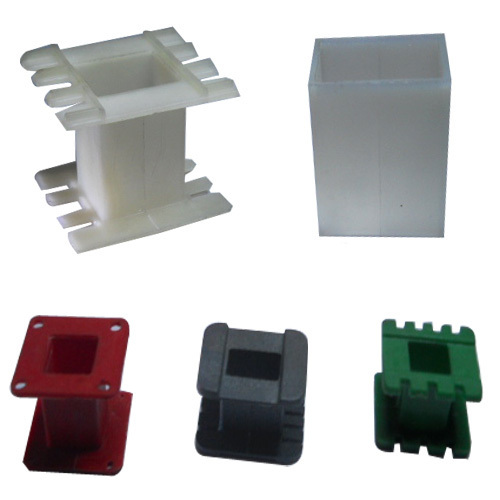
this is the new school bobbin.
this is the new school bobbin.
An externally hosted image should be here but it was not working when we last tested it.
Last edited:
Your so called new school bobbin is called Pi winding. See here for an example:
Valve Amps: Output transformers
Cheers
Matt
Valve Amps: Output transformers
Cheers
Matt
Never saw such a bobbin or a transformer wound that way.
Can you show such a transformer?
In any case, wavebourn´s objection sounds quite plausible, I´ll agree with him unless physical proof to the contrary.
In any case, why on Earth would you want to
As of the "Lenard" link, it sound quite misguided and presumptuous:
Can you show such a transformer?
In any case, wavebourn´s objection sounds quite plausible, I´ll agree with him unless physical proof to the contrary.
In any case, why on Earth would you want to
???? just wind it right and call it a day.easily change a primary or secondary section
As of the "Lenard" link, it sound quite misguided and presumptuous:
What?Transformer winding is an extension of the fitting and turning industry.
You *think* you do?Few people working in transformer winding companies have a knowledge of electronics or valve amps.
So nobody knows anything ... so now you come to the rescue ....Most valve amp manufacturers have a basic academic understanding of output trannys, but often have a limited or incorrect understanding of the physics of transformers or how they are made.
Academic formulas for calculating the design of output trannys is available in many text books and web sites. There is no need for this page to repeat academic information that is readily available. This page gives an overview of the physics that governs the performance of output trannys and helps give a perspective that academic text often omit.
Last edited:
Thanks for sharing! I do aware that C core uses such i so called new school bobbin or PI winding in this case. what about EI core,would it be better in sounding and lesser capacitance leaking which produce better high frequencies?Your so called new school bobbin is called Pi winding. See here for an example:
Valve Amps: Output transformers
Cheers Matt
Never saw such a bobbin or a transformer wound that way.
Can yiou show such a transformer?
In any case, wavebourn´s objection sounds quite plausible, I´ll agree with him unless physical proof to the contrary.
In any case, why on Earth would you want to ???? just wind it right and call it a day.
I am afraid i dont have a photo of a ready made product winded in this bobbin, as MATT BH showed in the link some UK manufacturera made them, and The German made them also (I think is Siemens and TFK) so it is not new school but the traditional bobbin i believe is an older way of winding.
this is the new school bobbin.
An externally hosted image should be here but it was not working when we last tested it.
That's not really "new school" and it has been used for output transformers for quite a long time. It is called vertical sectioning and actually it's simplest form is pretty common!!! It's the PP transformer with intermediate flange that is also used to get perfectly symmetric halves.
In fact I have also seen old transformers which had vertical sectioning but without having the physical flanges. It was and it is not common because requires more work and thus is a lot more expensive....
The only difference respect to power transformers is that: for power transformers the individual sections are used for either primary or secondary whereas for output transformers one has to have sufficient flanges or use it in combination with sandwiched primaries and secondaries.
Those multiple cavities are used to redistribute capacitance. If used for either primaries and secondaries like in power transformers will also give better insulation. However if no sandwich of primaries and secondaries is used leakage inductance will be too high for acceptable frequency response unless the number of sectors is comparable with the usual number of sandwiches used in horizontal sectioning. For large productions this is just more trouble. Instead if one uses both vertical and horizontal sectioning best results can be achieved. In power transformers there are generally only two or three which is not good as the result will not be HiFi by any standard.
So there is really nothing new under the sun.
Last edited:
")
I used to wind sectioned OT for PP, but they were also interleaved!
Sectioning I used for symmetry. Both sections had several layers of primaries and secondaries. If you separate windings on primary and secondary in different sections, I explained above why you will lose high frequencies. Both parasitic inductance and capacitance have to be minimised.
Sectioning I used for symmetry. Both sections had several layers of primaries and secondaries. If you separate windings on primary and secondary in different sections, I explained above why you will lose high frequencies. Both parasitic inductance and capacitance have to be minimised.
The real "old school" transformer is the "stick-wound" type. Ten to 15 windings were made at once on a rectangular cardboard core, with each layer wound, then separated by thin paper from the next layer. Once all the layers were done, the "stick" is removed from the winding machine and then cut into sections. Most vintage transformers and some new ones are made this way. The upsides with this method include: more predictable windings and better layer-to-layer insulation. The downsides include: requires special winding machine, less efficient use of the space in the "window" (area available for the wires).
Most audio transformers require interleaving to cut down on the leakage inductance, which hurts the high-frequency response. For a good summary, see the Radiotron Designer's Handbook, 4th Ed., pages 210 and 217. Interleaving can be done both horizontally or vertically.
- John Atwood
Most audio transformers require interleaving to cut down on the leakage inductance, which hurts the high-frequency response. For a good summary, see the Radiotron Designer's Handbook, 4th Ed., pages 210 and 217. Interleaving can be done both horizontally or vertically.
- John Atwood
Weighing in… while granted it has been decades since I seriously undertook transformer winding, in the few score (60–100) output transformers I wound, in experiments (where I too was questioning whether to interleave windings or go with primary-over-secondary, or secondary-over-primary, or to use sub-bobbins with their own winding cylinders), I found that the as-you-call-it “old school” of interleaved windings really was audibly the best. Though it caused some "fiddling", I liked the (P = primary, S = secondary) P-S-P-S-P-S-P-S-P topology (9 layers) as being basically "maker-optimal".
I had to fiddle with securing partial windings, THEN had to bind them all up and connect them later together in series (primaries) or parallel (secondaries) to get what I was looking for. However, if I recall … the “maker-overhead” was only about 3% more time. After all, there's potting to do, EI stacking, jiggling the whole thing to nice squareness. Clamping with bolts, varnishing and taping the layers. Hooking up colored leads.
It definitely takes time.
But as long as you have a cheap source of quality EI leaves, and plenty of magnet wire of various gauges, its a hêll of a lot cheaper than buying them commercially … once you get all the little doodads needed to do the job right.
It was fun.
I'm now suffering from old-age jitteriness too much to wind 'em again.
Sadly.
GoatGuy
Pat Turner was able to prepare OPTs where the intrinsic shunt capacitance and leakage inductance was well beyond the output stage response when valve Raa also comes in to the picture, and he just used horizontal interleaving. But any such high frequency response is not helped when using lower powered output stage valves with higher Raa.
Pat did use a messy two-pack varnish technique as the more practical diy alternative to a commercial bake-cool-epoxy vacuum impreg-overpressure impreg - bake process. That impreg process is a key aspect to stable reliable performance.
If the inherent transformer LC interaction, which Pat could typically push well beyond 100kHz, caused a noticeable resonance then that could typically be attenuated with a zobel set at a higher frequency where it just started to smooth out the first LC resonance, but otherwise had little interaction down at the amp response roll-off.
So I guess we may be looking for a solution when there is no fundamental problem (ie. in using horizontal interleaving).
Last edited:
The old school output trafos use paper bobins not platics.this is the example,old school bobbin.
this is the new school bobbin.
An externally hosted image should be here but it was not working when we last tested it.
The plastics bobins sports higher heat tolerance and made a poor harmonics content resulting in a cold SQ.
I highly doubt the 'bobbin' or 'former' material makes any difference at all. It may physically change the parasitic capacitance from innermost winding layer to core due to a dimensional separation distance, or a minor change in dielectric constant - but that should be very negligible in the bigger scheme of things.The plastics bobins .... made a poor harmonics content resulting in a cold SQ.
Perhaps you are just associating an OT made with a plastic bobbin to a seemingly similar OT made with a paper bobbin, without being aware of what other differences may exist internally and dimensionally.
The real "old school" transformer is the "stick-wound" type. Ten to 15 windings were made at once...- John Atwood
McIntosh Power Transformer Winding - YouTube
This is not true old-school "stick winding". As you say, there were no molded plastics, just paper wound-up thick for a former a yard wide; when wound, run through a saw to make a dozen units.
Here's some serious transformer winding.
Winding Process for Power Transformers -- YouTube
Last edited:
Pete Millet 807 amp used this paper bobbin Classic Tone model:I highly doubt the 'bobbin' or 'former' material makes any difference at all. It may physically change the parasitic capacitance from innermost winding layer to core due to a dimensional separation distance, or a minor change in dielectric constant - but that should be very negligible in the bigger scheme of things.
Perhaps you are just associating an OT made with a plastic bobbin to a seemingly similar OT made with a paper bobbin, without being aware of what other differences may exist internally and dimensionally.
Paper Vs. Plastic
Certainly it wont convince you either.
Well that link would have to be up there in the list of snake oil comparison techniques 101. Sort of like comparing a car's performance when four manufacturers provide their standard 6 cylinder engine for comparison. No engine details, apart from mystical paper versus not paper layering, but heh that's not their aim.
Last edited:
- Home
- Amplifiers
- Tubes / Valves
- old and new school of output transformer winding