It was a 22-0 22-0 audio transformer, for their 50w amp boards.
That sounds like a power transformer (not sure what you mean by "audio transformer"), this thread is about valve amplifier output transformers.
I don't find it odd at all. For guitar amplifiers I generally make a split primary (basically one on top of the other with just 0.1mm insulation in between) and sandwiched between two secondaries. Very basic, very simple. With the right source impedance I can get 20KHz only a fraction of dB down. That's technically the higher limit of the audio range but, for my standards, it is poor for HiFi output PP transformer.You don't find it odd they would sell an audio transformer of this type, for their well known amp kits?
I buy the 100VA one's to rewind. It was 162VA. Though I expect a VA rating on all transformers for this duty. How else would you specify one
How much power can it handle @20Hz? You can't answer that question using the VA rating of the core. Thus it is not an output transformer. for me it is more useful to know core cross-section and average magnetic path length.....
someone mentioned pi-winding, 2 vertical sections is not pi-winding. A truely pi-wound choke makes sense but a OPT? I can not imagine someone would pi-wind and horizontal section an OPT.
As to "old school", they used "paper" with a Dk of 1,6-2 "New school" uses mainly "plastik" with almost double dielectric konstant! How about that "improvement"?
Properties of the isolation between layers has an impact on bandwidth but the material of the bobbin should not be much to be concerned about
Last edited:
BTW- Here is a link showing some 'old school' audio transformer tests. It shows many vintage transformers were not that good. Push-Pull Transformer Test
CMA-01 4 RU 60 Watt+ Commercial Valve Monoblock Monitor Amplifier
CMA-01 Brochure.pdf
IIRC there were four primary windings sections and five secondary paralleled winding sections.
The subjective result was exceptionally good....clean, clear, precise sounding not unlike good SS but 'somehow' better, even more pleasant/fun when running with no loop feedback which is switchable.
The schematic is included FYI....worth a look.
Dan.
The CMA-01 is a very High Quality “Ultra Linear” Push-Pull Valve Amplifier for serious Audio Quality Evaluation or sheer Listening Enjoyment.
Features:
• KT 88 Output Valves
• Specially Designed Output Transformer by E. A. Sowter of the UK
• Truly capable Phase Splitter and Driver Circuitry
Must Hear to Appreciate the Quality of Valve Sound.
CMA-01 Brochure.pdf
The output transformer ran Pi Winding arrangement similar to the example lower down on this page - Output transformersTechnical Performance
Output Power: 60 Watts into 5 Ohms. Suitable for 4 and 8 Ohm Speakers.
Power Bandwidth: 60 Watts 20 Hz to 10 KHz, 40 Watts 10 Hz to 20 KHz.
Freq Response: + 0 –0.5 dB 10 Hz to 30 KHz,
HF Rolloff by internal passive RC filter, -1 dB 52 KHz, -3 dB 83 KHz.
Signal to Noise: WRT + 4 dBu in, 50 Watts out.
Wideband 87 dB,
20 Hz to 20 KHz 90 dB,
400 Hz to 20 KHz 93 dB.
Distortion: 50 Watts out into 5 Ohms.
100 Hz 0.5%.
1 KHz 0.5%
10 KHz 0.5%
The following figures were achieved under tests, and are not guaranteed.
10 Watts out into 5 Ohms. ( With AC Drive Trimmed)
100 Hz 0.06%
1 KHz 0.04%
10 KHz 0.1%
1 Watt out into 5 Ohms. ( With AC Drive Trimmed)
100 Hz 0.03%
1 KHz 0.03%
10 KHz 0.03%
Damping Factor: 20
IIRC there were four primary windings sections and five secondary paralleled winding sections.
The subjective result was exceptionally good....clean, clear, precise sounding not unlike good SS but 'somehow' better, even more pleasant/fun when running with no loop feedback which is switchable.
The schematic is included FYI....worth a look.
Dan.
BTW- Here is a link showing some 'old school' audio transformer tests. It shows many vintage transformers were not that good. Push-Pull Transformer Test
From this tests you cannot deriver the real performance of those transformers. This test merely shows the results with the circuit choosen to drive them. To get useful results you must at least drive them with the circuit it was originally designed for. Best would be to find and drive with optimum Ri, measure not only the max. power at 3db cutoff but also distortion and efficience.
A OPT is all about trade offs in design, manufacture and costs. A "good" transformer is the one with the best compromize between the conflicting demands put forward by the load and the circuit it is used in.
Ok, so someone made a real pi-wound transformer. And the benefit is claimed double BW, but compared to what? I can see benefits in paralelling secundaries, but otherwise? Higher stray inductance of the individual coils needs more and closer interleaving. What you win in lower windingcapacitance you loose again by the necessary closer spacing of the layers. Also, I can not see a half-layer in the transformer shown, so the half-layer advantage seems to be lost (propable do to the in this arrangement absolutely necessary high interleaving).
The key to estimating the relative leakage L of a winding scheme is to look at the magnetic path length for the leakage flux versus the main core flux. You want to get the leakage path as long as possible so that the main core (with its higher perm.) will be far more attractive for the magnetic flux.
The best way I have seen for that is to use long E laminations with thin interleave winding layers. Or to use a toroid with a progressive wind around the full circumference for each winding. Partridge I think were the ones who used the long E lams at one point for high performance. You can still get these lams, they are made for constant voltage ferro-resonant power xfmrs, just leave out the shunt gap lams. Thomas and Skinner sent me a 50 Lb box of the 1-3/8 LW laminations. (1-3/8LSW in catalog, LW deletes the center U holes)
These long E's typically will fit two standard bobbins adjacent, if you want to do a split bobbin balanced design.
The thin "pi" wound design probably achieves similar performance, you would compare the ratio of long to short (per winding) cross section (including the intervening insulation layer in either case) to compare relative to the long E scheme. But those "pi" wound layers will be hard to make and fit together practically speaking. What IS clear is that the typical OTs, made with scrap-less lams, (so a small winding window) are the poorest you can get.
For a SE design, one could use two E lam banks, with two bobbins or one long one, the E's stuck together with a small air gap between. Or even better, two long E banks stuck together with a super long bobbin.
Last edited:
The custom Sowter transformers had each primary and secondary in separate discrete partitions, ie no 'layering'. Works well enough that the National Sound Archive bought some such amplifiers. BTW Brian Sowter personally wound these transformers after staff screwed up a couple of attempts......all turns numbers must be exact to spec.Ok, so someone made a real pi-wound transformer. And the benefit is claimed double BW, but compared to what? I can see benefits in paralelling secundaries, but otherwise? Higher stray inductance of the individual coils needs more and closer interleaving. What you win in lower windingcapacitance you loose again by the necessary closer spacing of the layers. Also, I can not see a half-layer in the transformer shown, so the half-layer advantage seems to be lost (propable do to the in this arrangement absolutely necessary high interleaving).
Last edited:
Pi-wound = vertical layers
As pointed out earlier, sometimes a decent pp transformer can be made by using 2 cheap transformers, ditch the "I" and use the 2 "E" facing each other. The airgap is handy for the practically always presented dc imbalance
As pointed out earlier, sometimes a decent pp transformer can be made by using 2 cheap transformers, ditch the "I" and use the 2 "E" facing each other. The airgap is handy for the practically always presented dc imbalance
OK, maybe I mean sectioned windings, whatever......multiple individual windings mechanically separated on an EI transformer core and electrically connected as appropriate.Pi-wound = vertical layers
Dan.
Hi, I need some advice. I have a pair of custom made output transformers for a push-pull amplifier with the following arrangement:
The bobbin is horizontally sectioned in two halves. Each half has the P-S-P-S-P vertical windings. I am planning to connect six primaries in series (center tapped where B+ goes, maybe also an UL tap), and two secondaries in parallel, and then those parallelled secondaries in series (center tapped for GND). So P-P-P-CT-P-P-P and S||S-CT-S||S
If I give a numbering for each winding , it comes:
Section A: core side - P1-S1-P2-S2-P3 - outer side
Section B: core side - P4-S3-P5-S4-P6 - outer side
My question is: how shall I connect the individual windings for the lowest leakage inductance and best symmetry?
Anode1 - P3-P2-P1 - B+ - P4-P5-P6 - Anode2
or:
Anode1 - P3-P5-P1 - B+ - P4-P2-P6 - Anode2
or the same arrangement but P3-P1 swapped and P4-P6 swapped, if it does make any difference at all.
Also for the secondaries:
S1||S4 - GND - S3||S2
or:
S1||S2 - GND - S3||S4
Too many options 😕 Am I overthinking it?
The bobbin is horizontally sectioned in two halves. Each half has the P-S-P-S-P vertical windings. I am planning to connect six primaries in series (center tapped where B+ goes, maybe also an UL tap), and two secondaries in parallel, and then those parallelled secondaries in series (center tapped for GND). So P-P-P-CT-P-P-P and S||S-CT-S||S
If I give a numbering for each winding , it comes:
Section A: core side - P1-S1-P2-S2-P3 - outer side
Section B: core side - P4-S3-P5-S4-P6 - outer side
My question is: how shall I connect the individual windings for the lowest leakage inductance and best symmetry?
Anode1 - P3-P2-P1 - B+ - P4-P5-P6 - Anode2
or:
Anode1 - P3-P5-P1 - B+ - P4-P2-P6 - Anode2
or the same arrangement but P3-P1 swapped and P4-P6 swapped, if it does make any difference at all.
Also for the secondaries:
S1||S4 - GND - S3||S2
or:
S1||S2 - GND - S3||S4
Too many options
😕 Am I overthinking it?Isn't this one of those cases where a picture is better than a thousand words? If you can draw it, annotated with the resistance of each of the seperate windings, would that help?
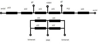
You are right. Attached is a sketch of a possible connection of the individual windings. Note the numbering is different from my initial post.
What I am not sure: would it be better to simply connect p11-p12-p13 in series, and similarly p21-p22-p23 in series? Also s11 and s12 in parallel, similarly s21 and s22 in parallel? On the attached diagram I made cross-connection between the sections, does it make sense? Or just keep it simple.
What I am not sure: would it be better to simply connect p11-p12-p13 in series, and similarly p21-p22-p23 in series? Also s11 and s12 in parallel, similarly s21 and s22 in parallel? On the attached diagram I made cross-connection between the sections, does it make sense? Or just keep it simple.
Attachments

Has anyone played with litz for the secondaries? Haven't done the math, but it seems like this would be a good place for it.
I would cross-couple the primaries. If we think of the order of the signal like this -
1st vertical section
Plate1 ; P1,P2,P3 ; B+ ;
2nd vertical section
Plate 2 ; P4,P5,P6 ; B+
I would then connect:
Plate 1 - P1 + P5 + P3 ; B+ ; P6 + P2 + P4 - Plate 2
This optimizes class B operation, where only one tube conducts and half of the primary is used. Not only it reduces primary1 to primary2 leakage, but primary to secondary leakage.
P.S. You should cross couple the secondaries as well.
P.S2 Is your second halve symmetrically wound? (that would require windings in the other direction).
P.S3 Let me know if you need technical analysis on other wiring options.
Last edited:
Thanks for the advice. I still don't understand why does the cross-connected primaries and/or secondaries version reduce the leakage inductance.
My transformer is not symmetrically wound. You mean symmetrical by starting each section at the outer edge and going inward? No, it is just wound left to right (first layer) in both sections without turning over the bobbin.
The wire length of the secondary s11 between the primaries p11 and p12 is shorter than the wire length of secondary s12 between primaries p12 and p13. So the DC resistance of s11 and s12 is different. Can I still connect them parallel? (Or s11 parallel to s22, s21 parallel to s12, that is an inner secondary parallel with an outer secondary).
1. So to make this clear with a simple example, if you were to connect both halves, you would do top-bottom-top-bottom, or vice-versa?
2. As for leakage, consider that in class B only half of the primary generates flux, while the other tube switches off. To achieve best coupling, you need ALL secondary layers in proximity to this half primary. As another simple example, if your "half primary" is located in one vertical section, it will have low leakage towards its layers in the same vertical section, but high leakage towards the layers of the neighboring vertical section. Remember your secondaries constantly work together and do not switch in halves.
2. As for leakage, consider that in class B only half of the primary generates flux, while the other tube switches off. To achieve best coupling, you need ALL secondary layers in proximity to this half primary. As another simple example, if your "half primary" is located in one vertical section, it will have low leakage towards its layers in the same vertical section, but high leakage towards the layers of the neighboring vertical section. Remember your secondaries constantly work together and do not switch in halves.
Hello, thanks again.
1. I don't understand this. I will connect both halves. There will be 2 secondary windings paralleled, and this in series with another 2 secondary windings. Let's call the sections A and B. I will connect A bottom and B top parallel, and A top and B bottom also parallel. Then these two in series (see my previous picture).
2. This makes sense, I will connect the primaries as you advised.
1. Makes sense. My advice is to cross couple secondaries as well. From my recommendation, something like this:
SECTION A: P-S1-P-S2-P
SECTION B: P-S3-P-S4-P
S1 // S4 ---- S2 // S3
OR
S1 ---- S4 // S2 ---- S3
// stands for being in parallel with ; --- stands for series connection.
IF WE ASSUME all secondary layers have equal turns.
Best regards,
Alexander.
SECTION A: P-S1-P-S2-P
SECTION B: P-S3-P-S4-P
S1 // S4 ---- S2 // S3
OR
S1 ---- S4 // S2 ---- S3
// stands for being in parallel with ; --- stands for series connection.
IF WE ASSUME all secondary layers have equal turns.
Best regards,
Alexander.
- Home
- Amplifiers
- Tubes / Valves
- old and new school of output transformer winding