Ifi Zen Streamer plus upgraded power supply - the streamer to beat??

Hi Fellow Audiophile nerds,

I know everyone likes to put a plug in for whatever products they happen to have in their system. I'm no better. But, I thought it would be worth sharing my experience with the ifi Zen Stream paired with an upgraded linear power supply, because it sounds great and seems like a really good value for what you get.

The ifi Zen stream is a small device, purpose built, with USB output. It cost me $400 USD on Amazon. Has been favorably reviewed by many including Absolute Sound, Audio Excellence Canada, and others. Some reviewers mentioned issues connecting to wifi, but I haven't had any problems. Ifi claims the product downloads firmware updates automatically. Streaming via Tidal Connect has been rock solid for me thus far.

I added a linear power supply from a British company called McRU - recommended by the British Audiophile. McRU makes a power supply for the Zen Stream and it costs around $350.

So, with this $750 combination, it seems I have a streamer with most of the features that you would find in high-end streamers from Auralic or Aurendor, and they retail from something like $3500 and way up. What I don't yet have is I2S output and a really good internal clock to reduce jitter before going into my DAC. But, Denafrips offers 3 digital to digital units, with their entry level Iris going for about $550 USD. So that's another option for those wanting to improve performance further.

How does it all sound? Going from a Bluesound Node 2i using coaxial output into a Denafrips Ares II, to the Zen stream with upgraded power supply USB output into the Denafrips Ares II the upgrade was very significant. More clarity, darker (less noisy) background, better instrument separation, and overall the sound seems to have a bit more weight to it.

Just thought I'd share this, and would love to hear others' opinions and experiences.

Kairos 3-way cabinet

Hi,

I'm thinking to start first project with Kairos 3 way.

I understand that I can't change the angle on the front TM baffle, am I right?

Any idea for simple cabinet design for this kit?
Classic design would be great, or something more sexy than the original Kairos 3-way design.
I have basic wood & audio skills but I want to learn through this project. I can use wood workshop/CNC if needed for certain parts.

I have 3.5m X 4.5m room, so I think to make the woofer cabinet as small as I can, something like 400mm X 400mm X 400mm, and maybe with small stands - Is it possible? even that I prefer classic design or something more attractive.

I have SVS SB2000
DENON AVR-X24000H - After the speakers build I'll find good amp
Music: Rock, Rap, Jazz, Indie & Blues.
Source: PC (Tidal, Hi-Res, Deezer & Spotify)
90% Music / 10% HT
Soon to buy miniDSPs
Listen alone most of the time and not loud - regular.

Thanks!

Itamar.

6L6GC UL PP Fun Time!

Hey!

It's been a while, but I've been noodling on a design for a 20W PP amp and decided to take a whack at a 6L6GC UL PP. Not sure that it's all it could be, but I wanted to keep it simple.

I have attached the schematic in progress, but should mention that the driver circuit is from the EL84PPP in this post and seems to be fine to supply voltage gain for the 6L6s.

LTSpice is indicating about .17% THD with 6dB of global NFB at 10W with about 20W of power available before clipping. 2H / 3H are about -58dB down at 10W / 1kHz.

Thoughts from the community would be much appreciated.

Kofi

Attachments

  • Screen Shot 2021-08-08 at 2.23.52 PM.png
    Screen Shot 2021-08-08 at 2.23.52 PM.png
    871.9 KB · Views: 1,422
  • Screen Shot 2021-08-08 at 2.26.21 PM.png
    Screen Shot 2021-08-08 at 2.26.21 PM.png
    726.5 KB · Views: 1,266
  • Screen Shot 2021-08-08 at 2.30.24 PM.png
    Screen Shot 2021-08-08 at 2.30.24 PM.png
    116.1 KB · Views: 1,209

Looking for someone to build me an SSE in the EU (preferably Poland)

Greetings!

As I have described in my introduction, I am weary getting into a DIY game for fear that I will get sucked even deeper into the audio rabbit hole, yet at this point in my hobby I would like to experience that SET tube sound, and I am on the budget. Hence, I am looking for someone to take my money and build me a device so I could just try to concentrate on enjoying the music for a bit and not look for the next thing.

I am in Berlin, I guess a builder from Germany could work, but ideally it should be a builder from Poland - I want to go with Toroidy.pl parts, and having a builder in Poland will allow to save a bit on shipping I suppose.

The build I have in mind is relatively sophisticated:

  • I am looking for a power amp, so no volume control or input selection - just one line in;
  • I would like to be able to use both KT88 and EL34 tubes, so will need a way to adjust bias;
  • I would like a tube rectifier;
  • I think I don't need the SS to tube rectifier switch, and, accordingly, the SS rectifier installation can probably be skipped altogether;
  • I would like an auxiliary power supply cap;
  • I would like a switch between the UL and SET modes, but if having the UL mode increases the cost of transformers (sorry, still a bit shaky on this part - I think the transformers have to support the UL mode?) then only SET is fine;
  • I am not sure if I need a feedback switch, or if Toroidy.pl transformers are producing enough bass response as they are;
  • in terms of enclosure it's up to the builder really, something simple with wood and metal plate is fine with me.

Of course, I will be willing to discuss and make compromises so that the optimal performance/flexibility/price is achieved.

I'd really appreciate if someone would take this on, please PM me if you are ready to do so.

Thanks in advance!

In Box Impedance Testing - DATS v3 vs REW

I was going to buy DATS so that I could get the "real" T/S paramters for finalising my enclosure design. And then use DATS to get my in-box impedance curves for my XO design.
However after doing some reading, I've decided to just rely on the manufacturer's published T/S parameters.
Which means I would only be buying the DATS for the in-box Impedance testing.

But I have been using REW for quite a few years, and although I haven't actually used it to do impedance testing, I am hoping that I would be able to get reliable results.

Is anyone familiar enough with REW to be able to confirm that REW would give me fairly accurate in-box impedance curves?

Monsoon audio planar speakers -- buzzing and distortion

Some of you may recall Monsoon audio -- for a time (late 1990-early 2000s) --- they became hot sellers due to their PC-related sat/sub models.
They sound quite good (mine are about 21 years old, but I retired them after about 2 years due to subject of this thread).
Both sats have a "buzzing" distortion over most of their freq range. They sound as if they are "blown" but BOTH being blown would be rare.
I think I've read that their powerful magnets can attract dust and that clogs their diaphragms.
The drivers are RIVETED shut so disassembly would be somewhat destructive. Don't want to do that just yet!
But I am open to other suggestions. E.g., how delicate are the film diaphragms to, say, compressed air blow-out?

1962834-5327e057-monsoon-mm1000-planar-speaker-system-computer-speakers-rare.jpg

Bass-Treble potentiometers in Baxandall tone control

Both treble and bass potentiometers can be either the linear or logarithmic type. Sometimes I see diagrams with "logarithmic" and
sometimes with "linear" noted in the diagram and most of the time there is nothing said or written about its type.
Can someone here shed some light upon this subject please? Or supply some links where I can read about it?
Of course I know the difference between those potmeter types 🙂
but anyway....

DC-DC CMOS (HEX INVERTER) REVERSE BIAS?

Hi everyone. Hopefully i'm in the correct forum.

I'm building a condenser mic and I supply it with about 80V dc from an Hex Inverter cmos circuit. The circuit I followed is attached. The cmos is supplied by +12V dc. I wonder if there is a circuit that provides -80V dc from the same +12V dc source -since it's provided by phantom power -(maybe by using the same circuit and changing something to give me negative bias).
I don't think that reversing the diodes' bias would work.

Thanks in advance

Ps.The voltage regulator and trimmer in the voltage input of the circuit are ommited.

Attachments

Triode-like curves from a n-channel DMOS (and not only)

Hi,

I would like to ask your comments on a design I've implemented on SS starting from George (Tubelab) UNSET (see details on dedicated section of the forum).

Driving a N-channel Depletion-mode DMOS (I've used the LND150 because they work well with high voltages, available where I want to implement this circuit) from the cathode through a pmosfet and giving local feedback through a voltage divider from drain to gate to ground.

attachment.php


Curves are very promising, and of course the local feedback (and so the reference gate voltage of the pmosfet) can be modified accordingly to change the curves of the two mosfets.

Of course the same concept can be applied to other SS devices too.

Thanks in advance for your feedback,

Kind Regards

Attachments

  • LND150-UNSET.jpg
    LND150-UNSET.jpg
    238.3 KB · Views: 2,886

Noisy / crackling output in right channel of Hafler 9505

Hi folks,

After probably a year of good use of my Hafler 9505, it suddenly got noisy in the right channel. The amp is used for mids/highs in a bi-amp setup. I verified it's the amp by switching the input to the amp with the left channel (noise stayed), and also by hooking up a different speaker (noise still stayed). Exercising the bridging and balanced/unbalanced switches did not make a difference.

When I got this amp, I resoldered some of the more baked solder joints in the high temp areas of the board, but didn't proactively replace anything. I haven't yet opened it up to take a fresh look, as it's at the bottom of a stack of equipment. I'll probably pull it tomorrow. Just wondering whether there were some common failure points in these.

Thanks,
Paul

Greyhill switch and noble wiring problem

Hello guys , I was searching the site for help on how to wire the greyhill switch to a noble pot but the only one that I found was one post by Peter Daniel a long time ago but Am confuse a little bit, here what he said :
Here's the drawing of Greyhill switch. To set it for 4 positions, you put the pins as marked: first one goes right above the groove (cut out) in a threaded bushing, the second one defines number of positions and should be inserted after 4 spaces counting from first pin. For 3 positions you place it one hole closer. Put tape over the holes, so pins won't fall out.

The tabs should be connected as marked, the separate ones are outputs, the ones in a row counted clockwise from output pins, are inputs. You can choose to switch both signal and ground for both channels independently and than you use both decks and all 4 output pins. An elegant way to do it, is use one deck per channel and upper pins for signal and lower for ground (switching). Use second deck for another channel, but this time use upper pins for ground and lower for signal (switching). This provides some extra isolation between both channels.

Best way is to use ohm meter to check connections on a switch.

In 4th position (if going by front panel markings) you should be getting Mute, which means input connection on those tabs (on a switch) should be grounded. That effectively grounds the amp's input and provides no signal.

Attachments

  • sw.jpg
    sw.jpg
    13.9 KB · Views: 128

BA 2018 linestage and Muses volume control

I installed the Academy Audio Muses digital volume control in the line stage. It had a Goldpoint 50k stepped attenuators. Now there is a difference -
the unit is really more transparent and refined. But I would like to know why this is so. I installed the kit for the remote convenience even without a led display. It is easy to install just replace 2 resistors connect and ready to go. Recommended.

FS: Fully built and *tested* pair of AKSA/XRK ALPHA 20 Class A boards

For sale is a fully built, and tested pair of XRK/AKSA (Hugh Dean designed) ALPHA 20 Class A amplifier boards. ALPHA stands for AKSA Lender P-Mos Hybrid. Boards have been cleaned extensively for removal of all flux. A generic set of 10uf input capacitors are included for the owner to install if preferred. Input BJT’s are matched (for Hfe) for super low dc offset (<5mV). Output FETs are the very expensive IXYS types. This is yet again an excellent sounding circuit using Nelson Pass‘ Aleph CCS in the output stage, biased at 1.8A. Gain is set at 18dB. More info regarding the circuit is right here. Board is UMS compatible.

Price is $OLD/pair fully shipped in USA. International shipping is possible at extra cost. PayPal preferred.

Best,
Anand.

Attachments

  • 65824834-644C-48AD-8786-B41DADA60580.jpeg
    65824834-644C-48AD-8786-B41DADA60580.jpeg
    591 KB · Views: 168
  • CD4654E8-6C72-4D84-8292-1352466C188C.jpeg
    CD4654E8-6C72-4D84-8292-1352466C188C.jpeg
    426.5 KB · Views: 159
  • 4245372C-9210-4CCB-869C-DE4F3B01A635.jpeg
    4245372C-9210-4CCB-869C-DE4F3B01A635.jpeg
    519.1 KB · Views: 164

FS: Fully built and tested Zen Mod Aleph J Zen boards

Built per ZM’s explicit instructions, I have a fully built and tested pair of Aleph J Zen boards using a matched pair of Linear Technology J74’s and IRFP 150’s. Input capacitor has been removed but I am including the standard 1uf WIMA capacitors. Board has been fully cleaned to remove all flux. Fully biased and tested. Another excellent circuit that tests well and sounds great on my NPXP. Board is UMS compatible.

$OLD/pair fully shipped in USA. Will ship internationally for extra cost. PayPal preferred.

Best,
Anand.

Attachments

  • DE34CBE7-C10C-40E0-AA91-D7E3C3ED5057.jpeg
    DE34CBE7-C10C-40E0-AA91-D7E3C3ED5057.jpeg
    493 KB · Views: 245
  • 01753259-49C3-4C0C-B0AF-535293DE4F13.jpeg
    01753259-49C3-4C0C-B0AF-535293DE4F13.jpeg
    553 KB · Views: 268
  • 4C768823-BCAD-4ACA-AD4D-A3961CFFEEC1.jpeg
    4C768823-BCAD-4ACA-AD4D-A3961CFFEEC1.jpeg
    453.8 KB · Views: 251

OIC - A utility for measuring speaker impedance with an oscilloscope

I wrote this for personal use, but in case it's useful to anyone else, I have made it publicly available. It's a Windows* command-line utility that takes a CSV file from an oscilloscope of a frequency sweep across an unknown impedance and tuns it into a CSV of impedance vs. frequency so it can be turned into a chart.

* It's Windows-only due to the way it's been packaged. If you're willing to compile it from source then it should work on other OSes too.

You need a setup like this:

setup.png


setup.jpg


To capture a frequency sweep like this:


Picoscope Woofer-C.png


Which OIC can process so it can be turned into this (actually not from the same speaker as the above image, but you get the idea):

plot.png


It's available on GitHub here: https://github.com/cheese83/OIC. I've also attached both the executable and source code to this post.

Attachments

Tannoy S8 LR Xover Schematic & Parts List

Hi everyone,

I bought a pair of Tannoy S8 LR DC units(2064) . I am planing to build diy S8 LR cabins.. Unfortunatelly I could not find the xover shematic and parts list of S8 LR speakers on the net. I found some pics of S8 LR xover only. You can see it the pics below.. The values of the parts on it are clearly visible except of the coil... I have no idea about the specs of the coil.

If anyone knows, please help..

Thank you..

x-over.01.jpg
x-over.02.jpg

TDA1541 noise after heat up

Hello to all diyaudio users,

I bouhgt not working Arcam Alfa 5 CD player. When I got the package, it turned out to be Arcam Alpha 5 plus. ( better CDM and separate clock power suplly ). Inside Arcam I saw TDA1541 S1 with crown. I decide to repair it.

I found and order new CDM9 pro version I repalced it. Now CD player works but... :

- when I use digital out connected to my Musical Fidelity DAC everything sound great.
- when I use analog out on cold player sounds great but after few minutes start hear noise from both chanel ( temp. about 45 C ). First low noise but after higher temp inside ( about 50 C ) louder. Over temp 55 C analog output is dead, zero music, zero noise.
- when cd player is connected to power inside temp is stil about 45 and in analog out still nothing after start.
- when I disconnected Arcam from power suplly and has an ambient temperature everything play after conneted to warm up.

It see like something is wrong with analog line, what I should check first ??

Capacitors around TDA looks not good but it can give noise in analog line ??

b52920d7353cea90.jpg


Or maybe TDA1541 is broken ?? but why I have still good sound on digital out ??

I have full scheme of this DAC but my knowledge is not that high 🙂

FS: Fully built and *tested* pair of Aleph J boards

I have a pair of fully built and tested Aleph J boards. Included are 2 pairs of input capacitors gratis, if you want to immediately install these boards into your amp and get going. All flux has been cleaned and it is now brand new. It’s already been biased and dc offset has been minimized. JFETs are a matched pair of NOS 2SJ108V’s and Gain/Aleph CCS MOSFETS are matched quads of IRFP240’s courtesy of member Dennis Hui. Played them extensively on my NPXP amplifier and this is an excellent sounding circuit. Gain is right at 20dB.

Price is $OLD including shipping in the USA. Extra shipping for overseas shipments. Paypal preferred.

1647094942042.png


Best,
Anand.

Attachments

  • 55EB89D5-D163-4A70-BA19-B75773CC5337.jpeg
    55EB89D5-D163-4A70-BA19-B75773CC5337.jpeg
    472.7 KB · Views: 166
  • E08E970A-1359-4874-A07D-705A7291995A.jpeg
    E08E970A-1359-4874-A07D-705A7291995A.jpeg
    405.4 KB · Views: 159

CEC AMP3800 2x64W amplifier - schematic ?

Hello !

Maybe somebody has a schematic for CEC AMP3800 ?

Initially had a humming noise on right channel, discovered floating ground on RCA input, rectified but after several hours come into protection mode, display: "ERORR".

Somebody, few years before, repaired one of driver cards (the left one).

I have no diagram and I need one.

Thanks

Attachments

  • cec amp.jpg
    cec amp.jpg
    149.1 KB · Views: 465

Better way to connect my XLR-Neutrik cables?

To keep the power supply part of my tube headphone amplifier away from the amplifier part
I use XLR Neutrik connectors and braided cable mantles for the power supply lines to the amp part.
But the way I have done it does not satisfy me (see attached photo).
Those coloured tapes and the mantles will loosen after a while and I have to redo that taping and mantle connection to the connectors.
Is there a nicer way to do that job?
Of course I want to keep using those connectors because they do an excellent job.

Attachments

  • Connectors2.jpeg
    Connectors2.jpeg
    331.6 KB · Views: 297

Thiel CS2.2 Xover Recap

All,

My first post here. I've sent my CS2.2 tweeters off to Thiel to be rebuilt since I blew them by using incorrect jumper setting on outboard preamp. In the meantime. I'm looking to re-cap the stock crossovers since they are around 20 years old now. The xover appears has several NP electrolytics being bypassed by 1uF Elcap Polystyrenes/Foil. I guess I have at least two options; 1. Just replacing electrolytics with same value OR 2. Upgrading to some nice film/foil and doing away with the bypasses (except for the parallel 100uF's). Any suggestions? I'm leaning towards just changing out the electrolytics in the spirit of keeping the original design. My plan is not having to go back into these for a while. I tried to attach a pic of the mid/tweeter crossover. Many thanks for any suggestions...

Attachments

  • 20171001_083833.jpg
    20171001_083833.jpg
    1,010.7 KB · Views: 734

Various Circuit Boards

I have the following printed circuit boards for sale:
1 Starving Student board (48 V version) …..$10.00
1 KSA5 power supply board …..$20.00
Sold! Dynahi boards by Kevin Gilmore…..$25.00 pr
Sold! Golden Reference power supply boards by Kevin Gilmore ….$15.00 ea
2 SSR3 power supply boards …..$15.00 ea

$6.00 shipping. If more than 1 board bought, I will combine shipping costs.
PayPal Gift and US shipping only

Attachments

  • IMG_0330.JPG
    IMG_0330.JPG
    117.2 KB · Views: 804
  • IMG_0333.JPG
    IMG_0333.JPG
    140.8 KB · Views: 779
  • IMG_0335.JPG
    IMG_0335.JPG
    117.5 KB · Views: 786
  • IMG_0336.JPG
    IMG_0336.JPG
    118.8 KB · Views: 773
  • IMG_0337.JPG
    IMG_0337.JPG
    104.2 KB · Views: 765

ESL high frequency chaotic modes?

John Atkinson has measured many ESL's for Stereophile and notes a "hashy" waterfall response.

This looks to affect the highs. I cant say Ive heard it. Does it matter?

Would it be beneficial to cross over to a tweeter/planar/ribbon so the panels are unloaded in the hashy zone
and also to save the amp driving into the low impedance zone.

1643811968305.png

1643815246092.png

1643816037519.png

1643816701770.png


Modelling of resonating wave modes:
1643814616478.png

Attachments

  • 1643811819791.png
    1643811819791.png
    393 KB · Views: 163

Crackling when recording form new digital piano

Greetings!

I get spike like pops, when recording my digital piano Casio privia px 1000 trough the output jack and into a USB mixer line input.
What could be the cause? I just got the piano a couple of days ago and i learned this tune and i tested the recording. Excuse the crappy playing it was late at night.

I attached a sample of my garbage playing so you can hear the "spikes" or pops.

Thanks in advance!

Acoustic amplifier switched impedance inputs

Hello This schematic is for an Ashton 60AEA Acoustic amplifier. the impedance is it 100K I think for acoustic preamp guitars.

To make it switchable input impedance between 1 or 1m5 and 100K So An electric guitar can directly in and Also a Guitar with a Piezo and no built in preamp So maybe thinking even 2M

I do not know if the 4558 will tolerate the value changes and the circuit will work with this idea?

Looking at the schematic I would make The alterations to R1, R2, and R9.
Also I noticed on the first channel R8 Is also a 100k resistor to ground before the first gain stage And question whether this should be altered also?

Thankyou for any advice.

Attachments

  • 9268D3D1-452C-41EA-97DB-FC8D712443A9.jpeg
    9268D3D1-452C-41EA-97DB-FC8D712443A9.jpeg
    48.3 KB · Views: 138
  • image.jpg
    image.jpg
    317.2 KB · Views: 128

Nut for binding post on AR 3A

Hello,

can you help me find a couple of nuts for the binding posts of AR 3A Improved? The original parts would be ideal.. but for the moment I could make it with two nuts.
I live in Italy and it is not easy to source parts sized in inches.
On my caliber the bolt measures 4.20 mm.

Thank you for helping 🙂

Fabrizio

Attachments

  • 273275949_10159846087714642_4382511201961771696_n.jpg
    273275949_10159846087714642_4382511201961771696_n.jpg
    380 KB · Views: 236

New Tang Band W4-616 (pair) S/N 404 and 416

Bought an extra set and never used them.
Paper cone S/N's 404 and 416.
They need some coating to sound smoother. I used C37 on my other pair.

Asking $80 + S&H from CT, USA

NOTE: I am not online every day so there may be a delay in responding.

Attachments

  • DSC04858.JPG
    DSC04858.JPG
    248 KB · Views: 102
  • DSC04861.JPG
    DSC04861.JPG
    258 KB · Views: 100
  • DSC04862.JPG
    DSC04862.JPG
    262 KB · Views: 116
  • DSC04863.JPG
    DSC04863.JPG
    269.6 KB · Views: 101
  • DSC04859.JPG
    DSC04859.JPG
    246.1 KB · Views: 93
  • DSC04857.JPG
    DSC04857.JPG
    260.7 KB · Views: 103

KrellClone KSA100-MKII Power Supply

I am building a KrellClone KSA100-MKII amplifier and need help deciding on the power supply design. When you make recommendations try to keep within the following scope:

1) Overkill - Keep every part with the thought of "over designed" if it says within the chassis dimensions
2) Quality Number One Importance - I am not concerned with the price, I am concerned with the quality of each part
3) Internal Chassis Dimension 258mm W x 143mm H x 358mm D

Does anyone have a schematic to help me choose the correct parts?

What Transformer do you recommend? What are the "perfect" values on the secondaries?

What Capacitors do you recommend?

What Rectifiers do you recommend?

Thanks!😀

Does this type of Desktop Digital Audio player exist?

I am looking for a Hi-Fi rack component type digital music player. The faceplate item listed here fits the bill, but is not very elegant, even if fixed to a black case.

https://www.thanksbuyer.com/12v-lcd...rt-fm-radio-aux-usb-with-lyrics-display-64325
I am looking for basically a CD- sized box with the touch screen and functions of an mp3 player : I find handheld mp3 players a real nuisance to use for a home system, for example a smart phone which I am using now.

I have attached an image of the Musicolet interface: the basic functions highlighted here are fine, touch screen or button operated. The problem is, this sort of device does not see to exist, unless with expensive SACD players.

musicplayer2.png

Near-field monitors

I'm about to start a near-field monitor project for my work desk using speaker units from SB acoustics.

The thing is that I don't know much about their units and I would like some recommendations for my project regarding choice of bas/midrange and tweeter along with box topology.

I would like to build an active 2.1 system with some small near-field desk monitors and a 8" sub using DSP to handle my crossovers. My initial idea was to use their Micro C kit as inspiration, but I'm not sure if I should keep it as a reflex box when I have the sub, or build it as a closed box midrange speaker instead.

I find it kind of hard to spot the main differences in sound from some of their units that seems to be similar, except for the choice of membrane materials, what can I expect to be different when choosing a ceramic over a paper or plast membrane?

First Build: low height under couch sub

Hello all,

I'm wanting to build my first sub. Due to WAF and room constraints, I'm needing to put it under a couch which is against a wall. There is a total of 11" of height with a butt in the seat, and the bottom is a trapezoidal shape of sorts, see the attached diagram. My receiver has Audyssey XT32 which I'll use for DSP.

I have a budget of $500ish for driver + amp. I don't have either purchased and will gladly buy used equipment.

What are a few drivers I should consider?

Which is a better design in this application, a down-firing 10" or 12", or side/front firing 10"?

If side/front firing, I'd put on a metal grill to avoid the accidental kick.

Thanks for the advice!

2022-01-30 20_20_31-SUBWOOFER Rev_ New 1.1+ New Design  (Active) - Creo Parametric.png

Grounding of casing.

My HPamp casing is coming along and I have to make arrangements to ground it with the 0 of the double supply.
I have 2 VHF transmitters nearby , cellphone tower at 800 m and nearby wifi to keep out.
It will be connected to my computer , but the ground of the signal is not the same as the metal outside of the computer case. I don't want to accidentally touch the HP casing against the computer's. Also it will be used on the bed with static electricity , and touching the HP casing is then touching the computer's audio output which I think is bridged. Of course I could spray paint or lacquer the aluminium casing , but that is not easy to do well and
after all the work I put in , I don't want to ruin it soaking it in solvent to get it off again.

So here's my question : Will grounding be affected if I connect it not directly to the 0 , the ground of the supply , but via a 10K to 100K resistor or even a 1M resistor ?
Also do openings for LED's , nylon bolts to connect the LM3x7 to the aluminum case for cooling or even a small plexiglass window for viewing the status LED's inside , affect the shielding much ?

Ariel construction

G'Day Everyone,

In a previous post I was asking about experiences with subwoofers to accompany Lynn Olson's Ariel speakers. On that thread someone was asking about my experience with them, so I thought I would start a new thread to answer that question, and hopefully it may be of interest to some of you...

Building the Ariel was not as difficult as I imagined at first. The way I approached the building was to take the time to make a router template for the sides. By using a template you guarantee that both sides have identical rebates for the internal baffling. Even though I have a table saw, I had the board factory cut all the baffling to width (for accuracy). The plans called for beech or birch ply. I had difficulty sourcing this in Australia, so I used marine ply (very expensive!). I built my speakers using a kit from North Creek http://www.northcreekmusic.com/ArielFAQ.html I used the value kit, and mounted the crossover components in the upper portion of the speaker box, behind the transmission lines, with a removable back plate. I will try to attach an image of the plans, as amended by me. A friend of mine borrowed the templates and has built his using an external active crossover. He is pleased wit the result, but I have yet to listen to his pair to compare (he lives in Melbourne, I am just out of Sydney).

I finished the basic cabinets last year, and I am l am pleased with the results. These speakers really shine with vocals/jazz music. With hard rock and large orchestral works the sound is at least as good as my old speakers, but there is not the order of magnitude of improvement that I experienced wit the vocal/jazz/chamber music.

The most difficult part of the construction is what I am doing now: covering them with veneer. I decided to cover them with jarrah veneer using the PVA glue/hot iron technique. I may have done something wrong, but it was a disaster! The veneer blistered and bubbled and looked a mess! I am almost through with the tedious task of slicing the bubbles open, injecting glue underneath and re-clamping. I will post some pics of the finished speakers when they are done.

Here is a link that you have probably seen, but was somewhat useful: http://indigo.ie/~walton/ariel1.html . He does a good job, but I was left wondering, after spending mega dollars on crossover components and valve amp components, spending a few quid on a router would have saved him a whole lot of heartache!

I have driven the speakers with two amps, and old Adcom 555 and an inverted gainclone. I am building a four channel gainclone based on BrianGT’s boards, but have yet to check them out with the Ariels. My aim is to build a tube amp next year, but have yet to decide on topology/tubes. I am in the process of building an active crossover based on the boards by Rod Elliott http://sound.westhost.com/project09.htm

Please note, I have modified the plans that are posted below, they have not been checked or endorsed by the designer Lynn Olson.

Attachments

  • ariel-6c modified2.gif
    ariel-6c modified2.gif
    34.3 KB · Views: 5,144

First Tube Build - which kit?

Hi there - I'm thinking of a new project for 2022, and never having owned tube amps I'd like to build something. I've successfully built an Aleph J with help from this group, and think I'm up to building a tube kit. Definitely not interested in flying solo on tubes with a scratch build; need a proven design and kit. Speakers are high sensitivity Zu Omen Def (2x10" full range w/ horn loaded tweeter, rated at 101db 1W/1M, 8 ohm) so I don't need a ton of power. Speakers sound amazing with the Aleph. I'm looking to try the "tube sound" and hoping for more 3D soundstage and "bloom" if that's the right word. Music is wide range, lots of live Grateful Dead, jazz, female vocals. Mix of vinyl and streaming. I'd like to continue to use a pre-amp (currently running a Schiit Freya (solid state) and considering a change to Freya tube or other tube pre in the future)

Right now I'm thinking of maybe the tubes4hifi M-125 monoblocks (http://www.tubes4hifi.com/M125.htm)...but also wondering if I should go for a 300b like the Elekit TU-8600. Obviously these are at sort of opposite ends of the tube spectrum...what do you think I should do and why? Budget should be in the $2-2,500 range but flexible.

Orion XTR 2500.1 Dz 2x Blown PS FETs and rough travel via USPS 🤬

So I finally scored an “awesome to me” Orion amp pretty cheap, for my own personal use, which I’m really stoked about cuz I couldn’t/wouldn’t drop retail $$$ on it with my current budget 😅 and it only had 2 blown PS mosfets on last bank. It took a rough ride via USPS but nothing was damaged or came loose even, just a hard knock to main body and side panels bent to ****, which I already straightened out, it was like it was literally thrown while it was stuck in Indianapolis USPS for 4 days ...

So to start I removed all PowerSuppy & Output FETs and both Rectifiers, booted up to get an initial probing, booted right up pulling only .06 amps in idle, not in protect.

Square wave on each of the PowerSupply Gate @ 22khz.

I see no waves or voltage over 1v on any of the OutPut or Rectifier pads.

I see ?sawtooth/triangle? waves & square waves on the SG3525AP.

There’s 2x LM393 MICs to the right of the 3525, I see various voltages ranging from 1v-12v but no waves on each, the voltages are not the same on each pin, I have them written down.

The IR2110S on output riser card has pins 11&3 + 7&10 shorted off/on board, and shows barely a volt on each pin, same with the LM393 next to it, barely a volt on each pin and neither have any waves, of course right since nothing is getting proper voltage?

So I checked the pins leading up to output card (a set of 4 at each corner) none have over 1v on them, there looks to be a voltage regulator, IRFBC30 above the transformer that’s above the riser card with a heat sink attached to it, barely a volt on each leg.

I’m new to this amp/board/design, I don’t know how it exactly works, if it needs PowerSupply to be working to show signals/voltage on the output section or not or if it needs a signal via RCAs, etc. I have ordered the last 2 IRFP4868 @ Mouser (every other vendor in the USA seems to be out, even eBay) I wanted 8 new matched PS FETs but got 2 so I can at least test it with the other 6 that tested good and within similar spec, I also ordered 6 new matched IRFP1405 for the Output section even tho they tested good and are all within similar spec as there seemed to be some molten backs, getting worse from 1 to 6, with 6 actually having blackened TIM near it too, you can see how bad it is in pic, will not sit flat against heat sink now.

All the FETs had those MESHA type solder shims but none were soldered on, just TIM used. I have TO-247 size blue thermal pads and high quality TIM I can use instead if need be, but ya that’s the jist of it right now, worried there’s multiple damaged pieces from rough shipping ride and/or from PS blowout cuz so many of the same ICs have different readings, there’s like 5x TL027 as well that all read different diode check wise that don’t seem to be on same trace and/or same resistor. O thing else test bad diode wise. I may be posting this early as I don’t have the FETs to get the Power Supply section up and running yet to test section by section, I also don’t know if and what it needs PS/Output/Signal wise to even be able to test each section so hoping someone with Orion XTR experience can advise.

This is a “stay in my collection forever and run ‘til I finally get an HCCA” amp. I know that don’t really matter but I’m excited to get one in finally as Orion is my fav besides Alpine, hoping the repair isn’t crazy cuz I’ve heard that the output card/section can be a nightmare even for experienced techs ...so I’m def approaching this cautiously wanting to confirm working sections by sections before soldering in $30-$50 FET sets. Any help greatly appreciated, ty 🖖🏼

Attachments

  • 4C330450-12AF-43A5-A4EA-CB65435E84CA.jpeg
    4C330450-12AF-43A5-A4EA-CB65435E84CA.jpeg
    602.9 KB · Views: 308
  • 2423FFF4-E2B3-4955-9844-B8D5B681B48F.jpeg
    2423FFF4-E2B3-4955-9844-B8D5B681B48F.jpeg
    345.7 KB · Views: 188
  • 5141306D-2102-4D73-808F-D7FD5AA4F805.jpeg
    5141306D-2102-4D73-808F-D7FD5AA4F805.jpeg
    617.3 KB · Views: 212

What shapes instrument sound!

I have a project build here

https://www.diyaudio.com/community/threads/instruments-amp-y4-trio.383281/
While learning to make custom filters and eq for this, I had a moment of ponderings and came up with this. It could be drivel for all I know as I am still taking baby steps with electronics. Please point out the holes in my understanding if you find this of interest

Learning how filters and tones are configured raises another question. I don't think it's only eq'ing of particular frequencies that shape sound. From careful listening to the harmonics (am I using this term correctly? Please educate) produced around each fret and how that fret is played, I have come to the belief that to shape sound from an instrument;

1 - multiple bands of eq in the relevant area of the instrument, at least 4 bands for a bass instrument. I think apart from the level pot, this is the first shape step to shape a frequency curve, but this doesn't alter the "voice"

2 - each band should have two parallel circuits that are more complex and contain a high pass to one side and low pass to the other. These two adjacent circuits need level pot, range pot, delay pot and reverb pot. The "voice" circuits to then mix back into the that tone bands output

This is the only way I can see to truly shape a bass guitar "voice" with analog. So each tone band consists of tone knob, upper harmonics level and reverb and lower harmonics level and reverb. My own voice is fairly low to where a lot comes from the subwoofer too. I can "shake" and add inflections while singing to suit the moods of different songs. Indian music composer R.D. Burman had his own unique singing style that he distorted with gargling type sounds at various reaches. With this, I infer that a distortion level on each of that three parallel circuits per band will do a job too

Basically this means that each band of the tone controls get 9 knobs or so. This is just my thots from what, I don't know whether it's on to something or coming from ignorance. After I finish the amp/cab to a usable level, I am going to seriously learn to implement this. I haven't seen it done like this before and if I am the first one to think of this break down then I would enjoy it to be known after me as the "Bassinga" (bass singer) system. If it's already old news to split each band and adjust harmonics individually like this, then I hope someone points it out

Free higher fidelity and smoother musicality?

Hey. Fellow true music audio nirvana hifi seeking dudes. 🙂

The term ”burn in” signal simply reaks of bullcrap and old snake oil.

Wellz.

Play this on your system. 10 hours. High volume. Not insane, just medium high. To get them tweeters, midranges, and multiple large woofers to soften up.

Get them to effortlessly reveal the mcrodetails. The warm and juicy details. The powerful room and sofa shaking firm and powerful bass. And sub bass.

The class A Pass Sound 🙂

Do it!
A serious listening test whitout a 24 h warmup is not a serious listening test?

Do the mnimum 10 hour pink noice system stretch and warmup. Do you hear a clear improvement?

Login to view embedded media

For Sale Finished DIY F6 amp

Hi,

I have a fully finished F6 for sale. One of the most universal diy FW amps if you ask me. Selling it because I desperately want to finish other long going projects and need some cash to push it. As you can see on the photos it is a very clean built (I have a bit of old about it so clean solder joints, all flux washed off, parts aligned etc 🙂. It uses a bit bigger 5U 300mm chassis I got from Italy. PSU uses Primrose audio grade 400VA transformer. As you can see all wiring done with the connectors so you can later on put another FW boards into it if you want (sorry no pre tapped holes though). If you have any questions, please ask. Price is $1000 + PP fees + only US shipping (maybe it is not even at cost nowadays with all the prices went up). Thanks for looking!

Attachments

  • IMG_3120.jpg
    IMG_3120.jpg
    368.3 KB · Views: 511
  • IMG_3121.jpg
    IMG_3121.jpg
    329.9 KB · Views: 632
  • IMG_3125.JPG
    IMG_3125.JPG
    522.1 KB · Views: 654
  • IMG_3126.jpg
    IMG_3126.jpg
    470.8 KB · Views: 652
  • IMG_3123.JPG
    IMG_3123.JPG
    482.8 KB · Views: 571
  • IMG_3124.JPG
    IMG_3124.JPG
    536.7 KB · Views: 548

Soft Start Circuit Connection Point - Idea (need feedback)

I'm building a stereo amplifier, my first ever build. It will be a dual-mono design.

This amplifier will be based on the carcass of an old , broken, Adcom GFA-2535. I have discarded everything except the two hefty transformers (center tap) which supply 35V to their secondaries. There will be two power supply sections, each with 40,000uf filtration. The two amplifier sections will be MOSFET kits I purchased from AMPSLAB. 60W per channel. Everything goes back into the original ADCOM case.

I am also installing soft-start modules. One for each channel. These are the relay type. I purchased the bare boards from that auction site. They are USA designed and manufactured. I now have built and tested the boards.

Here is my idea. I would like to keep the existing wiring harness that supplies 120V to the transformer primaries intact (as is). Can I connect the soft-start modules to the 35V secondaries, ahead of the rectification boards? I'd appreciate your thoughts. I'm sure there are some good reasons not to do this but to me, it seems like it shouldn't make a whole lot of difference. And it would make wiring a little simpler (I think).

Help with missing low-end on two-way speakers

Hello,

I have several sets of Boston VR-M 2-way speakers. A couple M60 and a couple M50. These are identical except five of cabinet and driver. Each has dual sets of posts for bi-amp/bi-wire with the connection pieces for using single wire.

On a couple of them (one of each size) there is no longer any low end sound. Whether the connection piece is in place as usual or not (and connecting wire to the lower end posts only) there is no low end.

Where do I start to diagnose this problem? What is the likely culprit?

Thanks

Eico HF-22 Clones with Thermionic Labs OPT's

I'm interested in cloning a pair of Eico HF-22 monoblocks, as I think the Mullard style of topology will be a little more forgiving in terms of transformer selection. I'm interested in using the 50 watt ultralinear OPT's sold on Ebay by a Greek company calling itself Thermionic Labs. They seem very high quality, run a little over 3 Benjamins for a pair, and the specs seem right on, with 6k6 primary impedance and 43% UL taps. I'm curious if anyone has ever used their product, or any others I might consider first. Also, I would love to hear any other advice from folks who have been down this road before. I plan on triode-strapping the EF86 tube

Beginner Help with Power Transformer Wiring

Hi guys, please go easy as this is my second build and I'm still a bit dyslexic with regards the primary and secondary wiring basics. I'm confident with safe IEC wiring and the on/off switch but lost on the power supply board wire colours.

In the pic attached what colours do I put in 1 2 3 4 on the power board module?
(I've just positioned it like that for ease of viewing)

Thanks in advance for anyone with the knowledge and patience to help.

Also please ignore the two small bottom green circuit boards as these I don't want, so just imagine the pic with the tranny wires all loose.


20220303_100836.jpg

Philips AZ6801. Damaged brain?

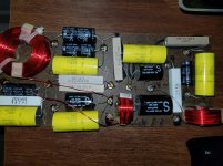
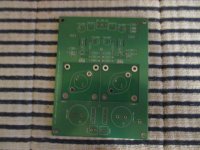
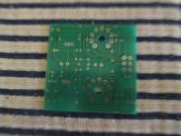
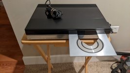
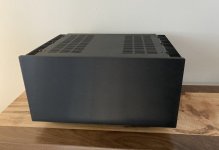
Hi all. I'm triying to bring back to life this old player. AZ6801, philips. 1989.
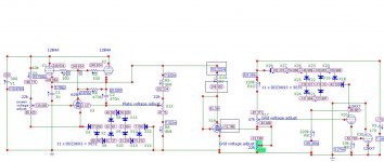
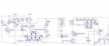
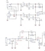
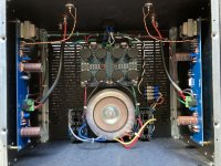
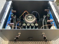
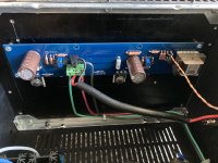
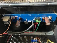
When I got it, it don't power up. I find fast why. The power regulator, which output 5v for the microcontroller, was bad, and in their out pin, it has 7,8v.
I change it for a 7805, and bingo, display began to works, and i saw the pattern that this player shows at boot, before do focus or anything more.
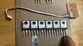
Other failure, was a TDA7072 burned, and now its changed also.
Ok, now, it powers up, but do nothing. ONLY moves the pickup to the initial position, and thats all.
Laser dont lit, Cd dont spins...
If I force láser on, cheating the APC circuit, it works and goes on. But, if i play with the levels of the door switch, and pickup initial position swicht, microcontroler dont mind, and no lits the láser nor try to focus.
When I test the original damaged regulator, i saw overvoltage in his output. It must be 5 v, but was giving 7,8, and, since it powers the microcontroller, i think that this overvoltage could fríed the controller.
But, hey, as i've said, the controller works well the display and positions the pickup in the initial position, from there, now it must power the láser, and do the focus search., but dont do anything more. So, is not died.
Thats all. What do You thing? Damaged brain? I'm losting something? I accept gratefully any help or thinking.
Marry Christian, and all the Best from Spain.
Albert.

Rohde / Schwarz Audio Analyzer UPD

Hello everyone,
I have a problem again and I'd like to address all those who keep the forum alive.
I have purchased a Rohde & Schwarz UPD. Unfortunately the box does not do what it should.

When I switch it on, the monitor turns white and it starts beeping.
That's it. The device was supposedly still working at the seller.
I have a UPL, that's it, turn it on, screen white, then the screen turns black and the routine runs like Dos Computer. Then a VGA graphic builds up and there the UPL is working.

Unfortunately the device is not yet with me because I live in Taiwan. But in 10 - 15 days it will arrive here.
What am I looking for!
Who has had something like this before or believes to know what it could be.
I search for
1. the service documents volume 1 and 2.
2. an operation instruction operator manual
3. the hard disk software

And a thousand good advices.

With kind regards
Johnny from Taiwan
jdl.taiwan

audio physic tempo 2 - one of tweeters started to sound quieter

Hi,

I have just bought for good price (i know why now) audio physic tempo 2. I had no chance to listen them before buying - these specific speakers. First thing I noticed was lack of bass but I found reason - very poor soldering. High tones were ok, but something happened during soldering and now one of tweeters sounds quieter.

I will check tweeters soldering too, but in the mean time I got this idea to check what kind of tweeter is in them and if neccesary replace them, but I can't find any reliable information.

Do you maybe know what exact speakers are in Tempo 2 - both of them.

Under Investigation All my bookmarks from before forum update are gone

I tried to search for my bookmarks and found only one I recently bookmarked, all the others are gone it seems, or what happened to them?

Edit:
It seems I must have mixed up the difference between Bookmarks and the "Watched" on the menu bar where the latter is sort of misleading as I thought "Watched" was a new feature on this forum keeping some kind of log of all threads I have ever watched, checking out "Watched" I just see a very long list of unsorted threads page after page and had no idea what I was looking at as it didn't resemble my neatly arranged and named folders.

It seems like bookmarks are a tool for saving a single post although it works for following a thread too, while the "Watch" is another type of bookmark sort of but only for a whole thread, if I got this right.

The poor thing is, those Watch-marks are now unsorted in random order without any tag/label/folder, and having over couple of hundreds of unsorted threads it's really difficult to find threads let alone remember why a thread was saved as I had lots of different folders for various topics I earlier saved under such as "Resistors", "Capacitors" etc., now it's near unmanageable and useless, terrible.

Will we have a folder option or some other way adding labels/tags for our "Watched" threads in the future, and, are the old folders stored somewhere and can/will they be restored at some point later?

fault-finding on board with an MCU

Can anyone confirm or reject the impression I am getting? I have two circuit boards (in inverter welders) with malfunctions, and each unfortunately has an MCU. All diagnostic procedures (tracing and checking signal paths) lead me to pins of 64 or 44 (respectively) pin MCUs.
I am thwarted by my inability to know what signals I ought to see at these most of these pins (apart from power supply and earth pins) because their functions are programmed into the MCU by the equipment manufacturer.
My hope was that it is possible to download out of the MCU its programme and work out what should be happening, but my Google searches suggest to me that this is in practice impossible.
How do we use the diagnostic skills and techniques we have managed with for years on all sorts of circuit boards if there is this impenetrable device on the board?
To illustrate the difficulty, one of the welders (TIG process) only activates its HF (which is supposed to initiate the welding arc) for a very brief pulse, whereas is should persist until the arc is established. This pulse emanates from the MCU, which should be responding to something either sensing the drop in voltage as the arc establishes, or the presence of an arc current. Both are sensed and their signal paths lead in plausibly fault-free ways to the MCU, but without knowing just what the MCU is supposed to expect before halting the HF, I do not see what to investigate. For all I know, it might be sensing some entirely different fault condition, and halting the HF as a protection measure. But how does one proceed logically?
Any thoughts?

I am Old school looking for SQ car audio

I am in search of a three way SQ car audio system. I have not had anything but an OEM system since 1985. I have considered a DSP and 4 channel class AB channel front end with a class D sub amp. My budget is $1k or less for amplification and DSP.

I presently have Dayton AMT Pod4 tweeters, Dayton RS 100-4" fullrange, Dayton RS 180P-7" midwoofer, and Dayton RSS265HO-4 subwoofer.

My Idea is to run the 4" full-range from 300Hz and up off of front channels. Then rolling it off at about 5kHz at 6db, and setting high pass close to that point with single cap.

I want to drive this system with a DSP that is capable of HD at 32 bit 192kHz. But finding such a unit that will fit my budget is not easy.
I am wondering if there are SQ units available that I can afford.

The only DSP unit that fullfills my cost and capability requirements that I have found is the Cadence DSP4.8. There were some negative comments made about noise and quality issues on the internet. So, that makes me skeptical.
As far as amplification is concerned. I am considering the Sundown Audio SAX 100.4 V2 class AB. And one of the new Sundown SFB-1500D or SFB-2000D class D sub amps when they come available.
Any insight and suggestions will be helpful and appreciated.

If I had the funds, I would go all top of the line Zapco. But!!!!

Power supply bypass caps - how and what

Here is an article I put together about how to deploy proper power supply bypassing capacitors to op amps and split supply circuits.

Types / values / dielectrics / and voltage coefficients are all discussed. What do you guys think? Agree? Disagree? Looking for any feedback or insights that were maybe not mentioned or touched on. Here is the article -

https://sparkoslabs.com/power-supply-decoupling-capacitors/

Attachments

  • OpAmpBypassCapsFI.jpg
    OpAmpBypassCapsFI.jpg
    74.9 KB · Views: 146

Class-D Amp LC-Filter: Coil heating

Hi All!
I am currently designing a Class D Amp based on TIs TAS5504 and TAS5152. I use the TAS5152 in 2x BTL configuration with 2x 10uH and 1x 0.47uF for each BTL. PVdd is 36V

So far it's working, but most of the coils I tested for the output filter heat up for 20-30°C above Tamb in idle (!) mode.
And those Coils are listed as "Coils for Class-D Amps". So I guess the resonant frequency of the core shouldnt be a question.
But to check it: (1) what should be the resonance frequency of the core when switching is done at 384kHz?

Interesting is that the coils do not heat up that strong when I place them in the TI eval-Board. So (2) my layout could be a reason? (I have a very compact board)
Or could there be some jitter on the PWM caused by a decoupling failure? (3).
I measure betweeen 0.5-1.0V Vss ripple at 384kHz. This seems to be a normal value to me (which was also confirmed by a Spice simulation).

Any help, hints or notes would be highly appreciated!

Thx and best regards,
Klaus!


P.S.: I foud the "heating in inductor thread", but this ended in nowhere 🙁

Please explain a servo circuit

I have been reading the forums, and the word "servo" keeps

poping up, I must have fell asleep when that topic was covered,

or I learned it by another name. I have been reading the "op amp

book", I have attached a small quote from chapter 1. Op amps

are very important, and I want to eliminate any confusion I may

have, please explain the servo circuit.

Thank You......

Attachments

Oh yeah another SSE build

After much reading and internal debate I am going to try the following SSE build


Power - Antek AS-2T350 (350-0-350)

Ouput - Edcor GXSE15-8-5K
Rectifier - solid state only


Tubes - JJ EL34L
Choke - Triad C-14X
Motor Run Cap - Pingcon CBB65A 100uf 450VAC


All other parts per standard BOM published on the Tubelab website. I do have a range of cathode resistors from 470 - 680 ohm at hand if need be.


I am very much new to this so will have many questions as I go along. First question of course does any of my choices present issues that will require solutions outside the standard build documentation? I decided to not follow the most standard build by using a toroidal power transformer and opting for ss rectification just because it appealed to me. End goal is to have an amp that will push my 4" full rangers from 80hz and up.

When measuring horns off axis response, which point do you guys measure from ?

I haven't measured a full set of polars from horns for quite a while. I think the last time I did measure I rotated the horn at its mouth (point B in the image) for the measurements.
Over the years I have read some people rotating at the throat end of the horn.

Which is correct ? (where do you rotate if you have a speaker with direct radiator bass units and a horn loaded mid/tweeter ?)

Thanks,
Rob.

Attachments

  • rotation.jpg
    rotation.jpg
    6.6 KB · Views: 96

Linear PSU with supercapacitor(s) - does it make sense ?

Dear Members,

I'm wondering if the huge capacitance of supercapacitors could be any good for DIY audio amplifiers in linear PSU-s. I know a voltage stabilizer (e.g. LM317T) already has a good PSRR (power supply ripple rejection) but how about using 1-2 supercapacitor(s) after the usual bridge rectification ? With current limiting of course to protect diodes (depending of type of course), that little bit of extra charging time is no problem, the main amp circuit is switched after PSU measured OK by the microcontroller anyway.

What do you think ? Has anyone done such a design ? I could also imagine 1-2 supercap(s) and then normal usual "chain" of caps like normal (low-ESR) electrolytes and finally the film ones on top of them. This way "speed" would be assured too, at least this is what I think.

Any advice, pro, cons, thoughts ?
I'm not a pro in electronics so I thank you for your patience 😉

New diy open baffle project: 3-way with AMT

Hi all,

after reading about open baffle designs and projects across the internet for several weeks I am coming closer to an idea what I would like to build myself.
Sine I have only built a few diy kits myself decades ago I hope I get some help in designing my speakers. I do not have any experience with that so far.

Inspirations came from: the pure audio project, spatial audio, GR research, blue plane acoustic, supravox and others.
My first idea was to go for 2* 15" woofer + wideband driver (e.g. Tangband...) but I have changed directions.

My idea is to go for a 3-way system using an AMT as tweeter. Soomething similar to the Spatial Europe mc series no 8: https://spatialeurope.de/portfolio-item/mc-series-no-8-en/

I dont want to play around with DSP or equalizers, I hope to get good results with just passive XO.
My first choice of drivers would be Supravox 215 (or maybe 165) for the mids, a Mundorf AMT (AMT23D6.1-R) with homemade waveguide. A reference design on the Supravox homepage suggest th 285 as woofer but I wonder if there is a good combination utilizing a 15" such as the Spatial Europe speaker.
I also looked into Acoustic Elegance drivers but hesitate because of the very high shipping costs to Switzerland where I live.

On further "requirement" is moderate baflle size, again the Spatial Europe mc no 8 would be just right, as well as the reference design on the Supravox homepage. The intention is that it should not dominate the living room, so about 45x120 cm is on the upper end of acceptable sizes.

For the beginning I hope to get some advice on finding matching speaker drivers, I have set myself a budget of max. 1500 EUR/CHF for drivers per speaker.

Open for inputs! I know that some software exists to simulate different speaker positions and baffle geometries, I plan to do some experiments with these software packages to better understand the implications different options....
Projects by fanatics, for fanatics
Get answers and advice for everyone wanting to learn the art of audio.
Join the Community
507,730
Members
7,886,121
Messages

Filter

Forum Statistics

Threads
406,133
Messages
7,886,121
Members
507,730
Latest member
plumb stupid