Hello

Hello to all, I'm Julija, a 20-year-old from Slovenia.
I've always had a passion for Hi-Fi. My father is an audiophile who introduced in me a love for good sound.
My first DIY project involves me in building some basic chip amps. I still have a lot of question. I wish to biild a large open baffle pair in the future.

Tubelab SSE - using a single meter to measure combined output tubes cathode current

Hello everyone,

I have a question, but I need to provide a rather lengthy introduction before stating it.

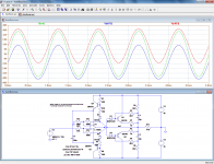
I haven't been active on the forum for a long time since I built my first SSE: the Mancave version. As life has slowed down for me lately, I've found enough free time to work on some projects I started about 10 years ago—an SSE to replace the current amp in my main system (almost done) and a full-blown steampunk mancave SSE version (all the weird parts are sourced, and the PCB is done; it just needs an enclosure and final assembly). I will post more details on both later. I thought these two would be my final builds, but I realized I have another enclosure and enough parts to build one more SSE before I exit the hobby.

My previous and in-progress builds have all of the options plus an ability to gradually adjust the output tube bias via either a precision pot or a switchable resistor matrix. They also feature a 100 mA meters between R17/R27 and the common bus to monitor the cathode current. For what would be my final build, I've decided to take a "minimalistic" (in my understanding) approach, with the amp operating in just two modes: triode with no CFB biased for EL34, or ultralinear with CFB biased for 6550/KT-88 selected via a single switch. However, I still want to be able to monitor the cathode current, mainly to spot a bad or failing tube.

Here is my question: would it be okay to connect R17 AND R27 to the same pole of a single 200-300 mA meter, and the other pole to the common (i.e., inserting about a 2 ohm or less single load between both cathode resistors and the common bus)? Or is this a bad idea, and would I be better off using separate meters for each channel?

Thank you to those who read this post all the way through. I'd appreciate your thoughts.

Attachments

  • IMG_3513.JPG
    IMG_3513.JPG
    739.8 KB · Views: 81
  • IMG_3572.JPG
    IMG_3572.JPG
    754.8 KB · Views: 80

Line Array Adapters for Compression Drivers

specifically for 1.4" throat

for example this one:

https://www.beyma.com/speakers/Fichas_Tecnicas/beyma-speakers-data-sheet-horn-SG6.pdf

is twice the price of this:

https://eminence.com/collections/waveguides-and-horn-flares/products/la_wg14#specifications

but is it actually better ?

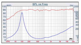
i noticed they use a different scale on the chart. if the charts are to be believed then Beyma is better - but why ?

and why can't they use a normal V-Dosc. is it patented still ? or is there some kind of issue with that design ?

Overnight Sensations Build Log 2025

After lurking this forum for the last couple months, my brother and I are going to build some bookshelf speakers. The amount of information you all have shared makes this a lot easier to try for the first time. Thanks to everyone!

We are using the Overnight Sensations design, modeled after dgunther’s faceted cabinet build. Unfortunately, I can’t find a build plan on the internet, so it’s more of an inspiration than anything.

My brother has a woodshop with some really nice equipment, so we are going for a furniture grade finish. He has 6/4 cherry and curly maple on hand, so we will probably use that. The plan at this point is to cut our own 1/8” veneer and apply over 1/2” MDF to create 5/8” panels. These panels will be used for everything except the baffle and removable back.

The baffle will probably be thick solid cherry, so that the facets can be cut. Probably around 1”. The removable back panel will probably be solid wood, also, so that we can build an integrated port with a nice roundover.

Attached are the drawings for the initial concept. Since we are using 5/8" panels with a 1" faceted baffle, some size adjustments from Paul Carmody's 1/2" and 3/4" versions needed to be made. In these drawings, the speakers have been lowered by 1/2". The internal volume is right around 278 cubic inches, which is between Paul's 3/4" and 1/2" designs (270 cu in and 280 cu in respectively). Hopefully that is good enough.

I'm hoping we can mount the crossover to the removable back panel, but I can't test fit until all the parts are delivered.

If you see any issues with this design, we are very open to feedback.

Attachments

  • v1 animation closed.gif
    v1 animation closed.gif
    3.3 MB · Views: 98
  • v1 animation open.gif
    v1 animation open.gif
    2.8 MB · Views: 165
  • v1 back off.png
    v1 back off.png
    96.1 KB · Views: 63
  • v1 exploded front.png
    v1 exploded front.png
    197.5 KB · Views: 55
  • v1 exploded rear.png
    v1 exploded rear.png
    169.1 KB · Views: 60
  • v1 front.png
    v1 front.png
    178.6 KB · Views: 55
  • v1 rear.png
    v1 rear.png
    129.5 KB · Views: 54
  • Like
Reactions: Netlist

Crossover upgrade by Tony Gee

Hi,

I’m maybe planning to do an crossover upgrade by expert Tony Gee. I will bring the speakers to him for measuring and the actual build.

I’m actually very happy with the tonality of my Spendor A7 speakers and don’t want that to change that much. I’m wondering if it could sound more open, playing with more ease and flow. With some more refinement, texture and layering, so without changing the tonality, or changing the sonic character or sound signature.What can I expect? Is it possible with just upgrading the existing parts with the same value by higher quality parts?

I’m a bit hesitant because I don’t know how it would turn out. At the moment I can listen to my set for hours without being annoyed by something I want to change. So it’s nice and balanced, even with a dual sub integration.

I have a pretty high quality system and my speaker placement is on point.

These Spendors were a hard find because I’ve got a valve hybrid amp so the impedance should been easy to drive. I’ve listened to several different speakers lately but they couldn’t wow me. They were even playing on 50k electronics. So a speaker upgrade isn’t an option. Like I said, I’m happy now but a bit more open sound would be just perfect.

Grtz

Attachments

  • IMG_5402.jpeg
    IMG_5402.jpeg
    78.8 KB · Views: 70
  • IMG_5403.png
    IMG_5403.png
    292.1 KB · Views: 68

requesting Sinclair X-20, X-10 information

hey guys,

so i've been trying to find any information i can on Sinclair X-20 (or x-10) amp. for those who don't know, they are probably the first commercial PWM amps made. they were fairly popular and apparently sounded pretty good considering the price, even tho production wise they were very faulty.

anyway, i've searched the internet and contacted as many people as i can, but have come to a dead end.
i'm just putting a request out there for any information. in return i will post what information i have if anyone wants it. i've basically got all i need except for the transistors. i know that some of them include the - MAT100, MAT101, MAT120, MAT121 and ADT140. But i don't think this is all of them, the ones i've just listed are all PNP but Q10 and Q11 are NPN. i also found out that Sinclair probably didn't make his own transistors, but instead relabeled ones from philco or plessey.
i'm looking for any information, but a scan of the original X-20 manual would be awesome. posted below is the what information i have on the X-20.

a scan of an article written for Radio-Electronics, September 1967.
A CLASS-D HI-FI AMPLIFIER article 1.jpg

page 2.
A CLASS-D HI-FI AMPLIFIER article 2.jpg

my transcription of the article.
View attachment A CLASS-D HI-FI AMPLIFIER.pdf

all the figures in the article, including the schematics.
articlefigures.jpg

i created this component diagram, it includes the position of all components.
component diagram.png

PCB
X20 PCB.png

parts list (has some holes with the transistors)
View attachment parts list.pdf

an image of the X-20 from an 1960's ad
x-20.png

if anyone can help i would be greatly appreciative. if anyone wants some more information they can PM me and i'll email what i have.

Will it harm my tweeter by doing this?

The original high-pass crossover for my tweeter from the factory is second-order slope, red line. I have converted it to third-order filter, green line.

1741610226727.png

1741610237001.png


Look at 3.5-8kHz region, the green curve is located above the red curve which means the tweeter will now be loaded with this frequency range.

I wonder whether this performing will harm the tweeters. And are there any disadvantages of doing this; such as introducing more distortion to the output, or stress to the voice coil and finally damage it?

For Sale Ian Canada UcConditioner Pro 3.3V with latest 450F caps - only 2h of use

I have two 3.3V UcConditioner Pro sets for sale. The very latest Pro version with 450F caps fitted. Got them from Audiophonics 2 weeks ago.

Price: -20% off Audiophonics price

No use for it anymore, as I went with the big 3000F Ultracaps (UcPure) for the 3.3V supply.

Matching LinearPi Pro high-current ultra-low noise Linear power supply (currently set for 3.3V, but can be set to 5V and 12V) are listed in a separate listing.

Zdjęcie WhatsApp 2025-02-23 o 21.40.46_3fb42578.jpg


Shipping via UPS/DHL/FedEx ~ 15 EUR within the EU.

Payment via bank wire of PayPal.

For Sale Ian Canada LinearPi Pro high-current ultra-low noise Linear power supply

I have two sets of Ian Canada LinearPi Pro liner PSUs for sale. The very latest Pro version. Got them from Audiophonics 2 weeks ago.

Price: -20% off Audiophonics pricing

No use for them anymore, as I went with the big 3000F Ultracaps with UcPure PSU/balancer for the 3.3V supply.

Currently set for 3.3V, but can be also set to 5V or 12V.

Matching UcConditioner Pro 3.3V ultracaps are listed in a separate listing.

1741015258816.jpeg


Shipping via UPS/DHL/FedEx ~ 15 EUR within the EU.

Payment via bank wire of PayPal.

Compression Dome Durability - Ketone Polymer vs Titanium

looking for the cheapest driver that can be crossed at 650 hz. found these two:

https://www.rcf.it/en/products/product-detail/ndt895

and

https://faitalpro.com/en/products/HF_Drivers/product_details/index.php?id=502020173

they're about the same price but of course being slightly larger ( 3" vs 2.5" ) the RCF is slightly more expensive

their impedance curves look about the same which means they can both go equally low in frequency since they also both have polymer surrounds - but the Faital has the dome out of the same polymer whereas RCF has Titanium dome and claims to be ribbed ( couldn't find pictures of the diaphragm to confirm )

ribs seem to be a novelty for RCF but also this driver has exceptionally smooth response for titanium dome ( much smoother than older RCF ) so i guess they did engineer some strategic ribs into the dome to control breakup ... this is apparently a newer driver and they probably had some computers to help with this ...

i would only use these as upper midrange to cross to a ribbon supertweeter so i don't really care about their HF response but rather i wonder which of them will last longer ? i would like them to last about 30 years of home use.

will the plastic dome of Faital sag overtime ? compression driver tolerances are tight - if the center of the 2.5" dome sags by even 1 millimeter that may be too much. it needs to hold its shape EXACTLY for 30 years.

why does RCF go through all the trouble of a ribbed titanium dome with plastic suspension when they can just make the whole thing out of one piece of plastic like Faital does ? is it for longevity ?

actually it seems RCF now has plastic domes but they have suspension from a different plastic ! ! ! while Faital's titanium domes are all titanium including the suspension. does that mean Faital is a cheaper brand than RCF ?

and as for the ribs on titanium dome - could they introduce some kind of stress points that weaken the material ? how hard would you have to push the driver for this to matter - or can it even matter at all ?

which driver would you get ? i think Faital is $305 from PE and RCF is like $320 from Beach Audio

i can see Faital looks a bit more efficient in HF but this may be due to a different horn being used - a more "beamy" horn will raise on-axis HF response ... and besides, as i said i would cross it over to a ribbon supertweeter

ST-35 - OPT

I am starting a Dynaco ST-35 clone build and have questions regarding which output transformer to choose.

The Edcor’s have 16 ohm taps so would drop right in and give me the proper feedback. But are overkill in wattage and Price.
Musical Power Supplies’s OPTs are less cost and smaller but have to choose between 4-8 or 8-16 ohm, I’m leaning towards the 4-8. Can I pull the feedback off the 8 ohm if I change the feedback circuit? How do I calculate that?
Thanks!

Welborne Labs SET DIY clone?

Hi, got this from estate sale in RDU, NC area several months ago. Unable to find any info on this amp except that the 300B driver circuit is a classic Alan Kimmel mu-stage driver identical to the Welborne Labs Laurel monoblock amps. Compared to the Laurel, the builder added an additional preamp stage, (I'm using 6SN7 but could use 6SL7's), a regulated DCV for filaments of the 6SN7, 6SL7 and 6AG7 preamp tubes and a DCV regulated bias supply for the 300B tubes. Waiting for some 300B to arrive to find out how well this amp works. Date codes on nearly components where I can see a date code are from 1998-99. See hand drawn schematic of one channel and the PS.

Attachments

  • SET_front.jpg
    SET_front.jpg
    163.8 KB · Views: 151
  • SET_top_front.jpg
    SET_top_front.jpg
    165.1 KB · Views: 104
  • SET_back.jpg
    SET_back.jpg
    177.2 KB · Views: 116
  • SET_Bottom.jpg
    SET_Bottom.jpg
    843.4 KB · Views: 158
  • SET_Amp_Welborne.jpg
    SET_Amp_Welborne.jpg
    96 KB · Views: 147

For Sale High end phono MM preamp

I am selling a very high-class MM phono preamplifier made according to the design of T.Giesbert from Elektor 7-8/2016.

Preamplifier in a housing with dimensions 13x6.5x25 cm (width x height x depth), running, functional.

The opamps used are very good LT1028 and LM833.

Power supply is 230V AC.

The casing is without any scratches.

The price is 160usd + shipping costs.
IMG_20240307_145625.jpg
IMG_20240307_145719.jpg
Bez tytułu1.jpg
Bez tytułu2.jpg
Bez tytułu3.jpg

Not-so-fun new project

I told a friend I would volunteer to fix her dad's old turntable, because that's what I do for "fun". She told me he said it was a top-quality, the best available turntable from the early 70s. When I went to his home to pick it up, this is what I found:
1741276879676.jpeg


It's a Realistic Lab12A. No way is this thing worth fixing, but I said I would fix it. And he seems really attached to it. He believes that this is a top-quality audiophile turntable.

If anyone has service manuals for this thing . . . 🙏
  • Like
Reactions: analog_sa

MA drivers in "gold, copper...) FR with woofer design advice needed

Full time in an RV, remodeling to a very high level, want to build some great speakers with some nice style to them so looking at Walnut or other veneer, small to mid towers, full range with one or two woofers and I know better than put the looks before the performance but I need to make myself and my wonderful wife happy🙂

I have been looking at the MA Pulvia 7 for the wide range up top, cross as low as possible and still good output then one or two Pulvia 11 for woofers.
(if there is a different driver pairing I should use I am open to suggestions but we really want the copper type color)

Plan to use foil inductors, great caps and resistors, wiring, etc.....

Also need to be pretty efficient as want to at least try them on my 10 watt push pull Baby Sophia amp and then later on if needed build a good D class amp but I also like the idea of the little tube amp on the top end and a class D for the woofers.

I would like to keep them narrow as I can, 40-42" tall and depth can be up to 18" and prefer front port, horn mouth, etc....

AND, play down low enough I can get by without sub(s) but if not possible I will build in an Image Dynamics ID15 either sealed or ported behind them then the towers would have to be a bit shallower, no more than 15" but 12" better yet.

I know, DIY, I should figure this out on my own but I have a huge list of ongoing projects and dealing with some health issues sappy my energy.

I am willing to pay a reasonable fee to one of our well seasoned members here for help on this if required.

I have a good table saw, big router, router fence, circle jigs, etc though I will need more clamps and will be working outdoors under a canopy weather permitting.

Thanks,
Rick (formally on here as RAAMaudio)
775-309-3701

For Sale Full range speakers

These are a diy build of the LT2000 using a licensed design from Bob Brine’s Acoustics. The driver’s are Mark Audio Alpair 12P’s. The cabinets are made from 18mm baltic birch, are stained mahogany with a urethane finish.
Dimensions: 43” tall 10” wide and 8” deep. The base is 12”x12”.
I’m selling because I’ve moved to an active system.
I was using these with an F6 (Nelson Pass amp) @ 25w per channel , a diy AD 1862 based dac (Miro) The source was a Wiim streamer or a MacMini (2012). Room size: 12x13x8
I mostly listened to jazz and a small selection of blues and rock.
$900 plus shipping
I’m located in Northern California

Attachments

  • IMG_3571.jpeg
    IMG_3571.jpeg
    107.8 KB · Views: 272
  • IMG_3570.jpeg
    IMG_3570.jpeg
    104.7 KB · Views: 266
  • IMG_3569.jpeg
    IMG_3569.jpeg
    110.5 KB · Views: 274
  • IMG_3568.jpeg
    IMG_3568.jpeg
    98.1 KB · Views: 249

Yet Another SuperCube III Failure

I've seen many people discussing it, but nobody really able to explain the root cause and probable repair for a low-output Definitive Technology SuperCube III subwoofer, or more accurately, its preamp from what I've read. It produces sound, but at an extremely low volume, and seemingly only through LFE. Gain knob works and controls what little volume there is.

Anyone have more in-depth details on this thing?

I've the skills to repair, but require some assistance diagnosing, as I absolutely SUCK at working with class D stuff.

Thanks!

Loopback vs USB audio gadget for CamillaDSP

In the past I had some trouble using loopbacks, due to (I believe) running them in virtual machines. My solution at the time was to set up a raspberry Pi as a USB audio gadget, to offer the system some direct hardware access. Now, however, I have abandoned the VM and will be running my media directly on the machine's native operating system (likely linux, maybe windows), which would make loopbacks a possibility again - and save fiddling about with a headless raspberry machine.

But.. I have it in mind that the USB audio gadget still had some advantages, I just can't recall what! It may have been lower latency, and/or perhaps it was that the source PC could set the gadget's sample-rate more easily, for example. Though I was comparing to loopbacks that may not be representative due to the VM.

Could anyone suggest what they have found a usb audio gadget's advantages to be? I already have both a Pi v4 and v5 so there is not a cost issue, but obviously (with another machine involved) more work would be needed for build and maintenance, running costs etc. TBH I've not found Pis to be especially nice or easy to use without additional customisation, so I would certainly want to put some effort into that if I were to go there again; things like automatic safe shutdown on power off etc.

Thanks,
Kev

My name is Alan

my first kit was a lecson ap1 and ap3 driving a pair of bc1. the power amps blew, both channels together burning the bc1 drivers.
the lecson pre amp was full of good intentions but veiled, to me.
next step. phase linear, something or others with the big meters,180w per chn, b&o eat your heart out 🙂 driving els57, bliss, stunning, & never over volted, ever :
then running around small london flats, ar7 with cambridge p50, i love that amp, drives quads 🙂
then remote cottage. cerwin vega r26 powered by rotel rb960. loud loud, tremendous rave kit.
now, els 57 driven by rb 960. it has been said the 960, with no output series r and c to ground and no output inductor, is poor into high c drive, my 960 drives els57 with 3m 1.5mm cables & works & sounds well.

a few hundred bits missed out 🙂
glad to meet you all

New to vintage!

Thank you so much for including me in this forum! As a young man in the 70s, our hobby was to cycle around town from stereo shop to stereo shop and collect brochures of the latest in HiFi. We looked at pictures, dreamed, and read data sheets until our eyes were big and wet! When college was on the agenda, I took a degree in electronics audio/video. Eventually, it became more education and a career in the sales of medical equipment and systems. Stereo systems and large speakers were replaced by a wife and children, dog, job and obligations. And so life has gone at a furious pace, until suddenly the children have become adults, the dog is gone, the job doesn't feel so demanding, and my dear wifi is still here, but I need a hobby! So the short version is that I went on Youtube and was completely fascinated by the large community of vintage stereo lovers, skilled technicians and the amount of equipment from all over the world that actually existed, and my old interest in hifi equipment was immediately brought back to life! So I got/bought some old receivers to be restored, brought out my vinyl collection, borrowed a turntable, my son-in-law came dragging a pair of old JBL L100s. So this hobby is fascinating, I love both listening in two channels, repairing electronics, learning a lot of new old stuff, and reading comments on diyAudio. Life is good 🙂!
  • Like
Reactions: Galu

Stereo imaging

Hi all,

So i im a bit curious about something,

I have a pair of sonos fives in stereo and i thought i had them dialed in pretty good for imaging...

I get a solid centre for vocals and i thought when playing music which has quite a wide sound that it sounded suitably wide and detailed.

Anyway i decided to have a play with another set of speakers that i was getting ready to sell (a rather beat up pair of wharfdale diamond 7.1 which are not considered to be that good, i had them running on my homebuilt valve amp which is about 30w pch and in the same position as where the sonos fives would be.

Playing the same songs i often listen to and im stunned by an almost holographic ultrawide soundstage and detail but i didnt seem to have a defined centre, so i tried different angles and such and the sweet spot was pretty much where i had them.

So whats going on, surely they either image or they dont but this seems to be a contradiction i had i wide soundstage with spread out instruments but the vocal centre was ill defined, but wow did the rest sound nice. They are rather limited on bass but i wouldnt complain for what i was listening to.

Now switch to sonos and the vocal centre is locked on solid with full body to the sound ie tonal balance however doesnt sound anywhere near as wide unless the track is recorded wide and then it springs to life, so which is correct?

Are the diamonds giving me artificially wide soundstage and the sonos are more realistic or are the sonos too narrow.

AudioLinear Speaker Restoration

Excuse me if this isn't the correct forum but I've acquired these early 80s three-way speakers as part of a bundle deal. They are either some store brand or potentially white van called "AudioLinear." I was considering just trashing these but decided to install my patented TempSurround™ and give one a listen and they seem to work well enough regardless of the glue that's dripped all over everything. So I've decided to install some actual surrounds but is there anything else I should do to these? They come full featured with dome tweeter styled "port", "crossover" caps, a nifty circuit breaker and that cool light up panel with some neato (they actually are) 8 ohm potentiometers. So here's my question, assuming time and labor is not a factor, is it worth doing any sort of upgrade or changes to these like putting in actual crossovers or installing damping material etc? I don't want to spend much money, frankly I thought the surrounds and gaskets were spending too much but here we are....

Attachments

  • front.jpg
    front.jpg
    649.4 KB · Views: 116
  • woofer_front.jpg
    woofer_front.jpg
    691.1 KB · Views: 104
  • woofer_back.jpg
    woofer_back.jpg
    531.2 KB · Views: 87
  • mid_front.jpg
    mid_front.jpg
    886.1 KB · Views: 87
  • mid_back.jpg
    mid_back.jpg
    1,017.4 KB · Views: 83
  • tweeter_front.jpg
    tweeter_front.jpg
    563 KB · Views: 84
  • tweeter_back.jpg
    tweeter_back.jpg
    902.2 KB · Views: 88
  • components.jpg
    components.jpg
    601.5 KB · Views: 92
  • eq_detail.jpg
    eq_detail.jpg
    391.4 KB · Views: 90
  • cabinet.jpg
    cabinet.jpg
    513.6 KB · Views: 101

2N4104 substitute

I'm helping a friend resurrect an Ampex 440 studio tape deck, and a problem popped up.

After running nicely for hours, one playback channel suddenly got noisy. The prime suspect is the first transistor in the signal chain, a 2N4104. In today's world, what would be a good sub for this "low noise" transistor? The specs:

NPN, non-Darlington
Small PTH package; TO-18, TO-92, etc.
Vce - 60 V minimum
Ic - 50 mA minimum
Gain - 100 minimum

Thanks.

ak

Hello everyone!

Hi everyone, I'm Daniel, a 21-year-old CS major from the Netherlands.
I've always had a passion for audio and Hi-Fi. My father is an audiophile who instilled in me a love for music and high-fidelity sound.
My first DIY project involves restoring 1960s slatted wood grille speakers. I still have some questions about the best approach regarding parts, so I hope to post my query on the forum soon.
Thank you for your time!

Original Transistors

Hello Members

Do you think it is worth removing known good transistors form quality equipment? Before sending it off to goodwill or the end of my driveway?
I have many quality made in Japan surround sound receivers I need to liquidate. Denon, Yamaha, Harman Kardon, Kenwood, Sansui, etc. Beyond that most likely 30 more units.

I am on Craigslist every day and nothing sells. Looking at charities like disabled Veterans? Can anyone help with that?

My question is. From my observations the certified original transistors might be worth the effort to extract.
Two of my clients suffer many implications of counterfeit parts. Often in delivered products that fail in the field!

With all the tools I have to get this job done efficient as possible. Is it worth the effort? It looks like the power transistors alone might be worth the effort?
Many of the units have dual transistors, Dual FET's and other desirable semiconductors.
I have a curve tracer, FFT analyzer, Noise figure meter, etc. I could supply test results as an option.

Plus the side benefit of transformers, etc.
Any thoughts?

Help please, i need to modify a 3 way car crossover (x6)

i recently bought 3 pairs of sony es mobile 3-way car audio speakers and i need to modify the crossovers. Everyone without expetion buys this kit and uses it in active set up to have acceptable results. The crossover points between the midbass and midrange tweeters are 1khz and 7.5khz and it should be 500-700hz and 3.5khz from what some users have tested their sony es mobile drivers.

I want to install these speakers one 3-way per door/side in a car using only 4 DSP and amplifier channels. I want to modify the crossovers. Atleast the highpass to the tweeter, the crossover between midrange and tweeter i need that one to be 4000hz. Can someone tell me wich of the components in the photos i need to change and with what?


WhatsApp Image 2025-03-08 at 16.20.38_e75c3122.jpgWhatsApp Image 2025-03-08 at 16.20.38_675fd278.jpgWhatsApp Image 2025-03-08 at 16.20.38_60236cc3.jpg

Please Critique - End Game Array V3

for those new to this train wreck V2 was here:


and now we are back to 5 way ...

1740819463331.png


actually i forgot to draw enclosures around 10" woofers ( red ) so just imagine it is there ...

this design retains the 4 boxes stacked on top of each other from V2 each with a 18" sub in it - because that just made sense ...

and the reason i had to redesign V2 is because it was based around 10" Radian Planar and it turned out that it doesn't use a Kapton diaphragm but some mother material that is likely less heat resistant as evidenced by fairly low power rating for such a large driver ...

so now we're back to the 8" Radian Planar which DOES use kapton and thus has higher power density per square inch of diaphragm ( about double that of the 10" radian ) because it can take higher temps ... this driver is shown as CYAN TRIANGLE in the sketch ... of course only the flat front of the triangle is actually the driver - the rear of the triangle is a chamber for it that is triangular so the output of MAGENTA midrange ( 5" cone ) can go around it ...

complete driver complement :

4.5 + khz - Aurum Cantus G3
https://www.parts-express.com/Aurum-Cantus-G3-Ribbon-Tweeter-276-412?quantity=1

1.2 khz - 4.5 khz - Radian 8”
https://radianaudio.com/collections/ribbon/products/lm8k-wide-band-planar-ribbon-transducer

320 hz - 1.2 khz - 5” B&C Bucket mid ( available from multiple stores )
https://www.bcspeakers.com/en/products/lf-driver/5/8/5NSM38

80 hz - 320 hz - 10” Beyma 10MC700ND ( sold by usspeaker )
https://www.beyma.com/speakers/Fich...rs-data-sheet-low-mid-frequency-10MC700Nd.pdf

16 hz - 80 hz - 18” NTLW5000 ( sold on Amazon )
https://www.eighteensound.it/en/products/lf-driver/18-0/8/18ntlw5000

Chips released a very long time ago etc9668rx and tda7273.

Извините, я нигде не могу найти документацию, структурную схему, эти микросхемы. Буду признателен , если дадите ссылку или распиновку микросхемы .Микросхемы очень давно выпущенные etc9668rx и tda7273 .

Attachments

  • 0-02-05-e99b6da2ac292b930e3e71a0ff69ee7943c045fe89b3ce4a17efcca3eb38938c_151b869e65c690eb.jpg
    0-02-05-e99b6da2ac292b930e3e71a0ff69ee7943c045fe89b3ce4a17efcca3eb38938c_151b869e65c690eb.jpg
    28.8 KB · Views: 29
  • 0-02-05-db64bb05cffbf0919d3ae4dcf73f6ff1b415d64a0137ac414b5582ca754276f1_dfff2623bccd6c32.jpg
    0-02-05-db64bb05cffbf0919d3ae4dcf73f6ff1b415d64a0137ac414b5582ca754276f1_dfff2623bccd6c32.jpg
    32.7 KB · Views: 26

For Sale Bundle of Dayton Audio woofers Peerless tweeter etc

I have a few items that I am selling as a bundle all together

1 - Quantity = 3 Dayton Audio Designer series Paper come woofers. two are tested for a few minutes and are in perfect cosmetic and functional condition and have solder on them. one is new. https://www.parts-express.com/Dayton-Audio-DS175-8-6-1-2-Designer-Series-Woofer-295-428?quantity=1

2 - Tweeter Peerless DX20BF00 3/4" Silk Dome. two are handled but new. these are amazing tweeters https://www.parts-express.com/Peerless-DX20BF00-04-3-4-Silk-Dome-Tweeter-4-Ohm-264-1472?quantity=1

3 - quantity = 1 Dayton audio measurement microphone NEW. https://www.parts-express.com/Dayton-Audio-EMM-6-Electret-Measurement-Microphone-390-801?quantity=1

all together paypal friends and family including shipping (weight = 18 pounds) $122.22
pictures: Login to view embedded media

Bundle of random DIY components everything shipped $33.33
pictures: Login to view embedded media 1- Quantity = 6 WBT RCA connectors
2 - quantity = 2 DC power connector large
3 - quantity = 2 DC power connector thin
4 - quantity = 2 DC power connector medium
5 - 20x 1uF mica capacitor for power supply
6 - power on/off switch with LED indicator
7 - power on/off switch with LED indicator
8 - brass ground connector
9 - quantity = 4 ceramic tube connector
10 - aviator connector for building DC power supply 4 pin
11 - aviator connector for building DC power supply 2 pin
12 - quantity = 2 IEC power connector with fuse and on / off button
13 - big AC power distribution with usb A and C
14 - gold plated copper sliding connector with shield around 40 quantity

everything together: $144.44 shipped.

Compression drivers - Radian 745be - B&C DCM50

I'VE GOT TOO MANY COMPRESSION DRIVERS!

1 pair Radian 745neopb-8. These have the expensive Beryllium diaphragms. These are listed at £1327 each. I will accept £1200 for the pair.

1 pair B&C DCM50-8 - £400

Please note. So as to measure the exit angles I've removed the bug screen from one of the drivers in each pair. (I've been careful to keep a small piece of foam in place so no debris could enter)

These are located in the UK.

Attachments

  • IMG_20241107_135237_576.jpg
    IMG_20241107_135237_576.jpg
    197.7 KB · Views: 105
  • IMG_20241107_135237_618.jpg
    IMG_20241107_135237_618.jpg
    207.4 KB · Views: 110
  • IMG_20241107_135237_979.jpg
    IMG_20241107_135237_979.jpg
    193.6 KB · Views: 111
  • IMG_20241107_135238_244.jpg
    IMG_20241107_135238_244.jpg
    186.4 KB · Views: 114

Contribution of Open source Audio Crossover design app

Hello guys. I want to make a contribution to DIY community.

Not very happy with XSIM, years ago I started to develop an app for audio crossover design. At first I wanted it to sell it via Microsoft Store. But I found the project was too big for a single developer so I decided to just liberate its source code. So this is a humble contribution for box builders and audio community.

Program is or tries to be a copy of the old and defunct LinearX CrossoverShop.

All core functionalities are working. Sadly project is not 100% complete, it still lacks some accessory features.

Current working features:​

  • Full circuit editor.
  • Animated simulation, live circuit response while tweaking components with a spinner.
  • All passive RLC components, and custom Impedance. Component tolerances/precision supported.
  • FDNR, Potentiomenter, Transformer and Switch components.
  • Active components like OpAmp, H block, Summer and buffer.
  • Loudspeaker component, supporting both SPL and Impedance vectorial curves.
  • Both grounded and differential voltage simulation.
  • Simulation of Voltage across and Current through every passive component directly.
  • Simulation of Power of resistors.
  • Own Docking Window System.
  • Potentiometer taper library.
  • OpAmp library.
  • Full support for floating sections or totally floating circuit.
  • Data import via text files.
  • Opening/Saving files in JSON format.
  • Ideal, parasitic and exponential models for RLC components.
  • Engineering notation for all controls.

Features Yet to Be Implemented:​

  • Digital FIR and IIR filters.
  • Data Export.
  • Graph Export.
  • Printing.
  • Remove an annoying hint box that shows "Ctrl+F4" message.
  • Circuit synthesis.
  • Unary math operations (gain, phase offset, etc..).
  • Binary math operations.
  • Minimum Phase Transform.
  • Delay Phase Transform.
  • Fast Fourier Transform.
  • Much much more....
Source code and install instructions here: https://gitlab.com/alsinaleandro/transition

Sample video example of a passive two-way design.

Please share your thoughts If you think this project deserves to be further developed. Please be kind.

Thank you!

Hello world!

Hello , I'm Edi , a Romanian guy who wants to get into making speakers . I have experience in 3D modelling ,sculpting ,and cnc machining ,so I thought maybe I can make some speakers with an organic feel . But after a little research i found out there's a lot of things to take into consideration when making a functional speaker lol. So I come in this community in hopes of getting some help along the way and to learn !

ZM's Magnetic Preamp

Many moons ago the Mighty Zen Mod and a few of the
Burning Amp crowd came up the coast to visit me at
Sea Ranch. While most of us were partying upstairs
ZM took over my workshop and spent most of the day
hacking away at a secret project. This effort resulted
in Planky, a discrete based preamp assembled on
plates of mdf butt glued together.

A very unique aspect of this design is the volume control
of relays and a tapped inductor. See the pictures....

Attachments

  • PLANKY 1.jpg
    PLANKY 1.jpg
    371.3 KB · Views: 820
  • PLANKY 2.jpg
    PLANKY 2.jpg
    631 KB · Views: 807

JFET guitar amp

Single channel, clean/crunch/distortion amp run by JFETs !

This project describes a small guitar power amp, built around four J112 JFET's.
(https://www.conrad.be/nl/p/on-semiconductor-transistor-bjt-discreet-j112-to-92-tape-3027573.html)
JFETs are well known to produce a very nice "tube" like distortion, so they are perfect to play around with.
My goal is to produce a variety of "sounds" with this amp: from "clean" trough "crunch" all the way to "distortion". I choose for a single channel approach.
See my schematic "JFET guitar amp V1.0.pdf"

Q1 is the input amplifier, which amplifies the guitar signal about 10 times.
RV1 is the input gain volume control.
Q2 amplifies the signal around 2.5 times, and is needed to drive the tone control. This is a one knob tone control, built around a lowpass filter (R8 C7) and a highpass filter (C6 R9) that are mixed with RV2. Setting the potmeter more towards "lowpass" gives a less high tone and vice versa.
Q3 and Q4 are two identical tone shaping stages. SW2a (SW3a) adds a boost in the gain by adding source capacitor C10 (C16). To balance the signal level compared to "non boost" mode I use SW2b (SW3b) to add extra attenuation resistors R17 (R18) in the signal path.
Q3 (Q4) have also a BIAS potmeter to adjust the working point of each JFET. With this control you can adjust the symetry of the signal, producing a more "crunchy" type of sound when set off centre.
With these two stages, you can play around and try and find the right tone you like!

As power amplifier, I use a standard KEMO module: this time the KEMO M033N. (https://www.conrad.be/nl/p/kemo-m03...dc-12-v-dc-18-v-dc-20-v-dc-18-w-4-130082.html)
They are cheap, reliable, and if you don't overdrive them, they work perfect!
RV5 is the output volume control. As you can see, the signal is well attenuated, because the KEMO module has an input sensitivity of 100mV max !!
I use 2 Celestion Ten-30 speakers of 8ohm in parallel, they sound great and are pretty cheap!
The powersupply is pretty straight forward, transformer/rectifier and 15V regulator.

I think this is a nice sounding amplifier, with plenty of power due to the 4 ohm dual speaker setup.
The tone shaping is a non standard approach, that gives a lot of options to find your perfect flavour.
The use of JFETS avoids the complexity of tubes with an equal (or even better) sound quality !!
I have add a few scope images of different signal shapes that are possible with both tone shaping stages.
Also some images of my prototype amp!


Have fun!!
IMG_20240825_110453.jpg
IMG_20240825_110109.jpg
IMG_20240825_110119.jpg
IMG_20240825_110126.jpg
IMG_20240825_110419.jpg
IMG_20240825_110512.jpg
IMG_20240825_110520.jpg
sodapdf-converted (9).jpg
sodapdf-converted (11).jpg
sodapdf-converted (12).jpg
sodapdf-converted (16).jpg

Attachments

Rotel RB-985 - noise sine wave/varying sound output

Hello all,

I have a Rotel RB-985, 5 channel amp which is quite old. But considering pairing it with my Yamaha RX-A6A for my 7.1.4 setup to offload the built in amp

However one of the channels(front lev) is making a sine wave/varying sound output, when nothing is connected to the input. Link to audio noise:
https://whyp.it/tracks/253536/rotel-rb985-noise-on-left-ch

I'm quite handy and open to try to solder / replace some of the electronics. But unsure where to start. Any advice?

Best Regards
Joakim

Attachments

  • rotel.png
    rotel.png
    775.5 KB · Views: 119

Upgrading rec-play preamp I.C. in 80's GE portable stereo because of high noise

Hi. Don't know why I'm messing with this. It's a fixation right now. It's all apart on my bench and is time consuming to work on, so want to do everything to it at once.

It's a GE 3-5266B 5 watt per channel cassette stereo boombox. The issue is very high noise level, even with no tape playing. It plays normally, but it's crazy to me that this level of noise was acceptable, if normal. Are most GEs like this with noise? Select "tape" function with no tape in it, and you hear SHHHHHH even at half volume? I don't remember it. Have had several GE boomboxes in my life. Btw, I'm not talking about motor noise. With nothing running, the hiss is loud.

It uses an LA3220 14 pin DIP, "low noise" preamp with ALC. Have ruled out (I believe) everything external to the chip. The 5 volts Vcc is clean, replaced all the 40 yr-old caps (though none tested bad) in that circuit. Resistors are fine.

The first thing I did was float the input pins. Floating the + inputs caused no change (hiss/roar still there). Floated the - inputs, and silence. But, after tracing it out, the only reason I lost my noise is because I broke the feedback loop (from the output). The chip is generating the noise internally. No change when I disconnected the head wiring (from the board), floated the ALC pins, etc. No change. Replaced the chip with a new NTE1634, and it's no better at all.

There does not appear to be any newer, compatible I.C. available with lower noise. So, my thought is to make a replacement circuit, using OPA2134 op amps, or find a very low noise preamp w/ALC chip to adapt into the circuit.

Feel stupid messing with this or getting this involved with it. It's a 37-38 yr old tape recorder and who knows why I care about it, but would like to improve this circuit.

Did electronics repair for a living for about 18 years, and did warranty work (audio) at a dealer for Pioneer and Fisher in the 90's. After leaving that shop, I went to a "we fix everything" shop for ten years. So, I've worked on my share of every brand.

If anyone else has done any mods pertaining to this and has a recommendation, I'd like to hear it. Thanks.

Near field listening booth/cabin/closet/capsule - any benefits? Or too crazy?

While driving to work this morning while enjoying some really nice music in my car (pretty basic setup, but with better speakers - door midbass and dash tweeters, and some other speakers in the backdoor), I realized I actually really like what I hear. The relatively small speakers provide enough bass and loudness. On the other hand, I cannot really listen much at this level at home when other family members are at home. That lead me to an idea to build up a car sized listening booth in my cellar, sound isolated to enjoy music any time of the day. I imagine loudspeakers built into the front wall and the chamber shape/corners could be used to some advantage. Subwoofer could be placed under the seat. Construction would be wood with fiberglass insulation - like the room-in-room isolation booths some drummers use in their homes. It would be bringing the room and the speakers into a single system - but it would not sacrifice a whole room of the house, but just a part of one room. I just wonder if this is really worth the effort to build up the cabin/booth or if it is a complete nonsense🙂 I am pretty sure someone has had this idea before and something like this has been built already...

Hello! Long time speaker builder going amp technician!

Hello! I have been building speakers for a long time. I have some engineering education, have build electrostatic speakers, some simple circuits like that. However I want to learn how to fully repair amplifiers.

I will be starting with the following

Anthem PVA-7
sherwood receiver
some plate amps for subs
jolida fx=10
crown k2
blue circle bc-2

Hopefully you guys can point me at some good guides, and how to approach some of these that dont have schematics or service manuals.
Cheers!

Cack-handed soldering advice?

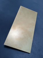
Hi all

Just recently bought a new cheap soldering / rework station to try and up my seriously lacking soldering skills (my previous iron has two settings: off and nuclear).

Being cack-handed / southpaw i tend to use the iron in my left hand and solder / tweezers in my useless right hand but I'm starting to think maybe I should reverse it and use my dominant hand for adding solder / parts but worry my right hand will end up stabbing something it shouldn't.

How do you all tackle soldering? What hand do you hold the iron in?
I respect everyone is different but interested to see what people do and their reasoning behind it

Cheers 👍🏻

Open Source DHT Estat Headphone Amp -- OSDEHA

Oups. I fell into the rabbit hole of electrostatic headphones. Those estats sound really nice to my ears!

Estats work at high voltage and low currents, so they can (and should!) work directly off the anode(s) of some nice vacuum tube(s). No transformers getting in the way!

There are a few estat tube amps out there. However, I could not find one that fits my needs (or wishes). The amp should be somewhat compact, and I want an output stage using directly heated triodes (DHTs). So I started thinking about designing a new amp. Maybe we can pull this off similarly to the OSMC project, which was great because severeal DIYers contributed to the design. Everyone is encouraged to contribute to the design process here!

The OSDEHA design files and documentation are available at GitHub.

Here is a (preliminary) list of some design goals (that may be updated in the future):
  • Use DHT tubes for output stage.
  • Output is taken directly from the anodes of the DHT output tubes. No transformer or capacitors to transfer the power to the headphones.
  • Input must take balanced input at signal levels of modern audio sources (mostly DACs these days).
  • Input stage and other circuit elements are welcome to use solid-state parts where suitable. I don't intend this to become a nostalgia festival.
  • Focus is on quality of audio reproduction and electronic design, not on low cost.
  • The finished amp should be reasonably compact.
  • The design is intended for use in the DIY community. If this project goes anywhere, full documentation will be provided in a public repository. Any use of the design (including commercial) will be allowed, but any modifications or extensions to the design that are used beyond one-off DIY builds for personal use are required to be re-published (and preferrably be fed back to this project).
Here's a (likely incomplete) list of some existing designs, circuits, and some other stuff that may provide inspiration:
So much for this opening post. I will post specific thoughts and questions later on, and am looking forward to what everyone else thinks!

Warning: This DIY project involves high voltage. Individuals utilizing the information provided must possess expert knowledge, adhere to stringent safety precautions, and accept all risks associated with electrical work. The authors and contributors of this project expressly disclaim any liability for injuries or damages arising from the use or misuse of this information.
  • Like
Reactions: stv

Howdy gang!

Hey All,

New member here. Looking forward to beginning my journey down the DIY Audio rabbit hole. A friend recommended me here after I watched him build some of the Pass Audio offerings. Couldn't believe the quality of sound he was getting. I have a decent set up currently with a DIY tube phono pre amp and a solid state Yamaha CR-1000. Excited to be a member of this awesome community!

Cheers,
Pickle

OSVA - Open source Versatile Analyzer

Hello all,

First, for the first release of the OSVA project, i start this new clean thread to avoid confusion.
This first post will be used in future to see major projects changes.
The OSVA is an new high performance analyzer that use SAR ADC from Linear-Technology/AD (LTC2380-24).
This project is born to follow up of my previous works done with the LT eval board and an CPLD eval board.
All information about this can be found on this previous post here :
SAR ADC for high performance audio ADC project [LTC2380-24]

So now, after some time of silence i keep you informed about project progress.
That has took more time than expected, time to learn Kicad too (and now Altium at work, Yuck!).
I do that only in spare time an i'm very busy at work right now).

Anyway, i now have finalized the PCB routing and i have ordered it to manufacturer (WEdirekt).
It will be on my desk, ready to start soldering in about ten days now.

From the previous schematics posted, i made several improvements.
I try to list them here :

Low noise regulators for ADC are replaced by LT3042 (as suggested by...).
  • I added 2 isolated analog output from PWM signals for external oscillator synchronization (enable coherent FFT).
  • The Input buffer LPF include two cutoff frequencies : 38.4kHz and 384kHz by default (they can be customized if required).
  • The inputs can be switched to single-ended or differential mode.
  • The input buffer is designed to use (at least) one this three buffers :
ADA4945-1 (New FDA OPAMP from AD)
OPA1632 (SOIC8 FDA from Ti, lw noise).
THS4541 (High speed ultra low THD from Ti).

I planed at first time to use the ADA4945 that promised extremely low THD level, but the latest datasheet release
show much worse THD level so i will use preferentially the THH4541.

As this project is fully open source, you can get all project files in it's new GitHub repo here :
OSVA - Open Source Versatile Analyzer


Complete new schematic can be found here (pdf) :
Github AA2380v1.00 pdf file.


Thanks to Kicad, you can also see how it will look like when populated. 🙂
AA2380v1.00_3Dview.png


Now, i must order some missing parts to Mouser (a complete bom ready) to ready when i receive the board.

There is some works to be done on others PCBs of the project:
- Front panel control board (leds and rotary encoder)
- AAPSU Power supply board (+5 and +/-Vanalog).
- AA10M08 Digital Logic board (Digital filtering and display interface).

I must also seriously work on CPLD software.
I hope to give others new soon. To be continued...
Regards.

Frex
  • Like
Reactions: Hipocrates

Chinese opamp PCB XH-A902

Hi
A friend ask me for a cheap buffer for class D chip which recommended a buffer because of low impedance of the power amp ips. i decide to by the cheap XH-A902 dual opamp pcb on aliexpress..i expect that the opamp is fake and not a real one.

XH-A902

i try to find a schematic but i found nothing and did reverse engineering. it is single supply.
input( R-GND-L) is left side if the power connector is on the buttom. output is R-L mirrored and on a 3 pin connector.
ground from signal in and signal out is decoupled with a 1µF ceramic (yellow in the middle of the 3 caps).

the opmap was checked over the quiecent current and it is not a NE5532. it draws 4mA...a real suck about 10mA.
according to my short search it could be a RC4558. i dont care...i use my NE5532

can this schematic work?
yes...(i expect not an inverted amp , there is no voltage divider on the non inverted input...?)

i changed the fb resistor to 2k2 and so i get a gain about 1.
i did a short measurement but the low frequencies down from 400Hz get very fast with low value.? why?
i changed the inputcap with a 10µF and the output cap (after opamp and 1k) with 10µf too. this doesn't t help.

any thoughts?

thank you
chris

Attachments

  • NE5532_Buffer_3.jpeg
    NE5532_Buffer_3.jpeg
    206.5 KB · Views: 508
  • NE5532_Buffer_2.jpeg
    NE5532_Buffer_2.jpeg
    151 KB · Views: 681
  • NE5532_Buffer_1.jpeg
    NE5532_Buffer_1.jpeg
    152 KB · Views: 490
  • Like
Reactions: arthur

oldish newbie

hi

been a diy audio enthusiast since middle school. then followed to get my degree in electrical engineering . from few months ago started digging through some old stuff and reconnected with my old DIY audio passion. bough a few vacuum tube old radio and a reel to reel tape player. also am reviving my old equaliser and a turn table and a transistor amplifier. changing alot of electrolytics for now. and addapting some cheap electronics one can buy from ebay/aliexpress, but finding also problems

Hi all!

Hi everyone , I am here after reading many many hours long different posts, that helped me in various repairs (or improvements) !

The last one to date is an improvement on the THD of Rotel RA 840 BX 4 , made after the repair led to one channel being hotter than the other, which I found out to be a common trait of Rotel’s from that age …

That led me to Ange’s post with a schematic to improve the RA 820 THD ,

https://www.diyaudio.com/community/...l-amp-thd-by-20db.275171/page-57#post-7846182 ,

which in turn led to my video Login to view embedded media
I made another one on the repair that I will soon post, where I highlight somewhat why some of this amps fail due to heat… Ange’s cure reduces that greatly😊

Looking forward lots of other mods and repairs.

Cheerios

Eric

Ps: I will soon share my repair findings on Alesis powered MKII that I couldn’t find on internet, but that are now repaired, I fixed the power supply and publish also some minor improvements to the amplifier section of that twin amp 😊

Typical HiFi seperate sized housing / enclosure on the cheap?

Hi all
Musing a different project to the one I've currently got on the boil. I'm on the lookout for a typical HiFi seperate sized enclosure / chassis / project box. Been looking at broken power amps on ebay and even old Sky boxes to gut and reuse. Where do you guys get your enclosures from? Bearing in mind I'm in the UK and am perpetually skint!

Cheers guys 👍🏻

New enthusiast

Hi,

New here! I’ve been into audio for a long time now and my upgrade path has been very pleasing. I’ve been sceptical about many upgrades I’ve done including cables, switches, fuses and other stuff. The main thing about this hobby is that I’m listening first and see if it’s an improvement or not. Different is not always better. So still trying to learn and stay open minded and now I would like to learn and have more information about crossover filters. I will post soon about that.

Thx!

Douglas Self Precision Preamplifier 2.0

Hello,

After some help sourcing parts please. Have bought the PCB from the Signal Transfer Company and require to source the parts for the switch banks. The information supplied with the PCB lists (I think) Signal Transfer Company's own part numbers and state that only they can supply. I have Emailed Douglas and he said that this would be altered. In the meantime, I need to obtain the manufacturer and their part numbers so that I can approach them directly for supply of same. Would appreciate any pointers you may be able to give on this.

Thank you


Neil
Projects by fanatics, for fanatics
Get answers and advice for everyone wanting to learn the art of audio.
Join the Community
507,708
Members
7,885,329
Messages

Filter

Forum Statistics

Threads
406,091
Messages
7,885,329
Members
507,708
Latest member
ahmadmusowwir