Update 8/11/2014
V2.1 of this ODA project PC board is now available. The materials for V2.1 of this ODA project are at the same Google Drive link immediately below, except at the folder 80x160mm -> 7_9_2014 V2.1. One of the sub-folders has a description of the changes between V2.1 and V2.0. The V2.0 build photos in posts #278 - 290, #301, #302, and #368 still apply since there were so few differences betweeen V2.1 and V2.0. I have a full set of V2.1 build photos posted at the V2.1 Google Drive link, with a text file for each photo section that talks about any differences between the two versions.
Update 4/10/2014
V2.0 of this ODA project PC board is now available. The part of this thread for V2.0 starts at post 272. For all the files go to the Google Drive link here: Go to the 80x160mm folder -> 3_19_2014 V2.0.
https://drive.google.com/folderview?id=0B67cJELZW-i8VmhVNk5PODNtZnc&usp=sharing
Go to the 80x160mm folder -> then the folder "ODA 3_19_2014 V2.0 fabricated" . There you will find:
* Layout and schematic in both png and PDF format. The PDFs can be zoomed up as large as you want to clarity.
* Bill of Materials (BOM) - the stuff you need to buy from Mouser or Digikey. Mouser has all of it but the LT LDO regulators, which you have to get from Digikey. Mouser is out of the pot at the moment but Digikey has those too.
* Gerber files. These are the board layout files you can send to any board fabrication house to have a run of your own boards made. I've been using Seeed Studio in China but OSH park is another good one.
* Build instructions. Plus I've posted a step by step photo log of the build in this thread.
I would advise using this V2.0 rather than any of the past versions at this point since it adds the DC output offset null feature. If you are working on a past version board, please be aware of the one marking error, C51 has polarity reversed ont he board marking. Be sure to flip it. That error is fixed in V2.0.
Please note: the ODA designed evolved over time from the first post in this thread, below, to what is shipping now in V2.0. The current version uses 3 NJM4556AL chips per channel in parallel (6 op amps total per channel), no longer uses an OPA627 at all, uses LME49990 chips for the gain stage, and many other changes. You may want to start with post #272 first to get up to speed on the current stuff, then go back and read some or all of the earlier posts for historical background. 🙂
*********************************************************************************************************
*********************************************************************************************************
NwAvGuy/RocketScientist never did get around to publishing his O2 Desktop Amplifier (ODA) before he disappeared last year. For fun I've taken a few guesses on what might be in an ODA and whipped one up.
😀
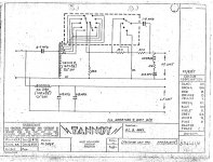
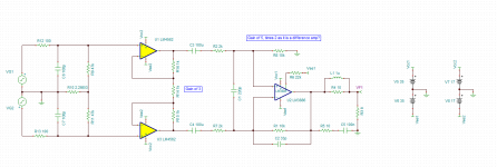
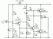
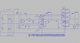
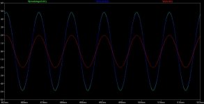
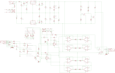
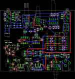
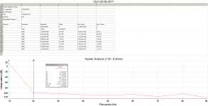
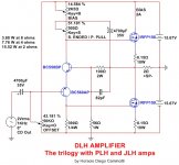
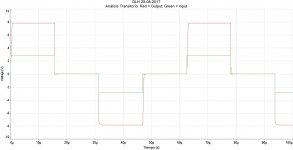
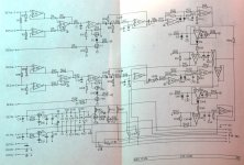
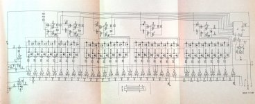
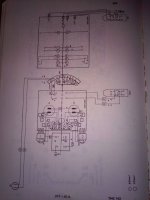
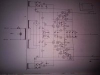
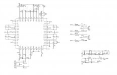
Below is an LT Spice sim of the ODA circuit on the top half, one channel, and the regulator O2 circuit on the lower half for comparison. From the plots the two outputs are virtually sitting on top of each other, green and blue, which they should be. The next two below are the schematic and about 2/3 of the way through a layout. Once the Chinese PCB shops open up in a week after the holiday I'll get one fabbed and stuffed. Once I finally get a working design I'll post the layout in the wiki section here for anyone who might want to DIY it. Since RocketScientist released his O2 under the gnu license, and this design is a derivation, I'll list it as being covered by the same gnu license for public DIY use.
This goal of this ODA design is to maintain the same basic design philosophy that NwAvGuy/RocketScientist used, but to try to bump up the performance slightly in most areas. Plus add some features that people have posted about and a few of the O2 mods I posted.
I know that one of RocketScientist's goals with the O2 was to make it cheap to be readily affordable. I've kind of thrown that one out here with an eye towards some improvements.
🙂 The OPA627 chips alone are $20 for the low end and $30 each for the high end. I don't have a dScope or AudioPrecision analyzer, so the final result here has not been properly measured, which of course was sort of the whole point of the O2, so fair warning.
Here is a summary:
Best new stuff:
- · Up tp +/-16Vdc power rails with adjustable regulators for up to a 11Vpeak swing. Useful for high impedance headphones.
- · Lower noise voltage regulators, LT1963A and LT3015. Probably won’t make any audible difference, though.
- · Twice the output current capability and power dissipation - 280mA per channel. Useful for low impedance and low sensitivity headphones.
- · 4 NJM4556A chips to handle the current and +/-16Vdc dissipation, two per channel. Uses the SIP 8 pin inline version, NJM4556AL.
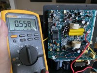
- · NJM2068 replaced with OPA627, which is now in a feedback loop with the NJM4556 chips to null out DC offset and reduce distortion even further. DC output offset voltage should be around 0.3mV = 300uV per channel.
- · Has input RCA jacks and output ¼” Neutrik jack in addition to better (Switchcraft) 3.5mm jacks.
- · Bass boost circuit – switchable on/off.
- · Rotary gain switch with 4 gain settings.
- · Relay-based no-thump circuit that waits 2 seconds to switch in the headphones and then drops them out quickly on power switch-off.
- · Should have even lower background noise than the O2 headphone amp at high gain settings. 4 layer PCB with full middle ground plane.
- · Volume pot is on the input now rather than the middle of the circuit, so it can attenuate “hot” sources as much as needed. Still no pot turning noise.
- · Coupling cap is on the input, 4x as large to work with the 10k pot vs. 40.2k resistor in the O2, to block all incoming DC from the source.
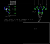
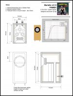
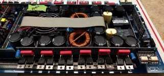
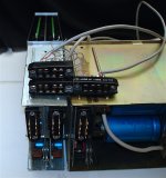
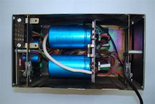
This version of the ODA uses the B4-080 case. In the layout below all the power supply stuff is now in the lower right corner, including the power plug. Having the power plug in back is something a lot of folks have posted about. The voltage regulators now line up along the back edge and are heat-sinked to the back panel of the aluminum case, one of the O2 mods I posted. So no finger-burning regulators in this one, although the transformer is now limited to 14Vac or 16vac, nothing higher or lower due to the input limitations of the new regulators.
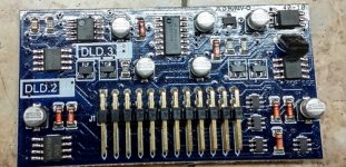
The 3.5mm jacks are higher quality Switchcraft jacks, with actual springs inside and not just springy metal, another thing a lot of folks have posted about (bad jacks). I've used vertically oriented jacks to make better use of the vertical dimension and leave more front panel space. I've included 0 ohm surface mount jumpers on the back of the board to disable the grounds on the input jack switches if using the RCA jacks - no more cutting board traces as with the O2 to add the external jacks. The design has a companion top board that slides in the top slot of the B3-080 chassis, upside down. That board has a Neutrik 1/4" output jack and RCA jacks that can be wired for input or preamp out. The top board also has space to mount a ODAC.
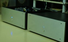
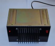
New stuff on the front panel now includes a rotary 4 position gain switch. Gains are 1x, 2x, 4x, and 6x. There is a bass boost switch for boost on/off. The resistors can be selected for any level of boost, such as 3dB, 6dB, etc. Another one of the O2 mods I posted. The power LED is now on the back panel, one for each supply rail to help diagnose dead power supplies. The unit has a (pico)fuse now too on the AC input and the power switch shuts off the entire power supply now.
I've included the output relay mod I posted for the O2 which delays the headphone output turn-on by about 2 seconds, then switches the relay out quickly when the power is shut off to prevent thumps.
The rest of the new stuff is in the middle. The gain stage now uses an OPA627 with a feedback loop wrapped around 2 NJM4556AL (SIP 8) chips in parallel on each channel, for a total of 4 op amps in parallel now on the output. The pot in the middle had to go to allow the feedback loop (DC) to function. The pot and coupling cap are now on the amp input, with the cap value adjusted up 4x to account for the 10K pot.
The new arrangement should nearly null out (around 300uV vs. 3mV for the O2) any DC offset on the output of the amp, given the exceedingly low 100uV max input offset voltage of the OPA627 and its tiny 5 picoamp input bias current, which results in nearly zero IR drop across the input resistors. This also means the pot won't have any substantial DC through the wiper even though there is no longer the coupling cap on the wiper as with the O2. Just another way around the silent-pot design issue.
🙂
The cap is still there feeding the pot though to block incoming DC from the source. Highly not recommended to bypass that. I've made sure the frequency response still matches what RocketScientist's design had on the low 10Hz end.
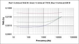
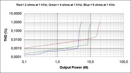
A by-product the the new negative feedback loop design should be even slightly lower distortion. RocketScientist had pointed out that the distortion figures of the output chips swamped that of the NJM2068 input chip. Essentially made the output chips the limiting factor on distortion. They were just a necessary evil to get the high current. The NFB loop should lower that output chip distortion a small amount. The OPA627 has excellent distortion numbers.
The design uses both surface mount and through hole components and has parts on both sides of the board, so it probably isn't a novice level of soldering type of DIY build, unfortunately.
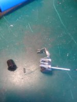


 Both concertos are dead now...