Hello everyone,
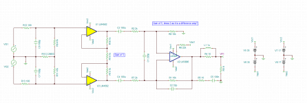
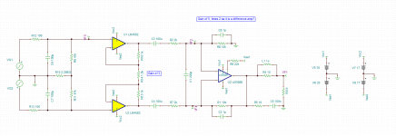
I have been learning about balanced signals lately and was wondering if attached schematics makes sense. I have drafted TINA TI simulation and it seems to behave just fine. However, it would be helpful to hear some input before assembling it.
Will it be ok to use LM3886 with the gain of 5 assuming it is acting as a difference amp - essentially combining inverted and non-inverting signals by adding their voltages together? Datasheet specifies minimum stable gain of 10, but uses non-inverted schematics.
For example, 3V on both inputs would give 6V in total - that is then multiplied by the Gain = 5 set by external feedback resistors?
Attached is schematics and simulation files.
Thanks,
Pavlo
Attachments
Last edited:
Define your "input". Vg1? Vg2? VG1+Vg2?
And WHY oh WHY are you using the poor power chip as a differential? Does it even have CMRR?
Your opamp stage has about no common mode rejection. (10dB?)
The usual (dare I say professional?) way is to unbalance before all else, then work unbalanced through most signal processing and any naturally-unbalanced stages. Such as a grounded speaker output.
Yes, lm3886 has cmrr rating graph.
It will not do the same great job as other opamps (lm4562 for example), but if external resistors that set the gain are 0.1% tolerance, the CMRR is than downgraded to 66db.
Or am I missing something?

It will not do the same great job as other opamps (lm4562 for example), but if external resistors that set the gain are 0.1% tolerance, the CMRR is than downgraded to 66db.
Or am I missing something?
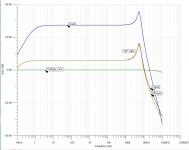
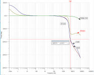
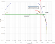
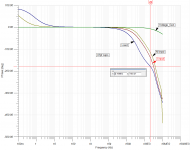
I wonder if adding two capacitors in parallel with R8 and R1 will be sufficient to insure HF stability?
Attached are frequency response and phase shift graphs for two conditions - using two 47pF compensating capacitors C2, C8 and using two 1pF (basically none).
Attached are frequency response and phase shift graphs for two conditions - using two 47pF compensating capacitors C2, C8 and using two 1pF (basically none).
Attachments
Last edited:
1 pF means that you will change the stability of the circuit if you wave your hand over it. Not recommended.
Tom
Tom
That i
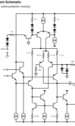
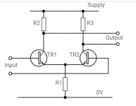
That is in a non-inverting configuration. My configuration is a difference amp. LM3886 difference stage has two transistors that output the same voltage - in either cases: if fed half signal each, or full signal single transistor. At least that is how I understand difference stage in the opamp.Taken from LM3886 spec:
"The closed loop gain must be at least 10 for stability.
Attachments
- Home
- Amplifiers
- Chip Amps
- LM3886 gain of 5 as difference amp?