You are using an out of date browser. It may not display this or other websites correctly.
You should upgrade or use an alternative browser.
You should upgrade or use an alternative browser.
Filters
Show only:
My personal interpretation of the Baby Huey with EL34
- By zintolo
- Tubes / Valves
- 12 Replies
Hi, after the request of @OldHector , I post here my own version of the Baby Huey with EL34 (that fits well with KT77 and other tubes).
I will also post some guidelines for other tubes like 6550 (I would avoid KT88 because the original pcbs have the sockets too close for KT88).
Let's start with a bit of hystory: this kind of amps have ultralinear and Schade feedback combined.
Schade original feedback (1938) can be found here:
https://www.dos4ever.com/uTracer3/Schade.pdf
Crowhurst reposted that kind of anote-anode feedback in 1952 here:
http://www.tubebooks.org/Books/Crowhurst - Audio Handbook No2 - Feedback 1952.pdf
Yves Monmagnon posted the PP Schade feedback (and phase inverter supply) in pentode configuration plus conventional gnfb here:
http://www.dissident-audio.com/PP_ECL86/Page.html
The EL84 development has been done in 2006 by @gingertube here using 40%UL and Schade feedback:
The EL34 version has been started by bandol (RIP) in 2018 here with 40% UL and Schade feedback:
Here I posted a similar thread with noted on the EL84 version:
Here I will report my takes on the EL34 version, but before a small introduction on Schade feedback:
Numerous tests have been done during the last 90 years, but just to report real measurements, I link some sources:
One is Broskie in 2001:

https://www.tubecad.com/march2001/
One is Bertola with his plts on Schade feedback only.
in 2013 he has tested on the curve tracer the 807a ( https://frank.pocnet.net/sheets/136/3/307A.pdf ) showing how Schade alone can triodify the curves:

source: https://www.bartola.co.uk/valves/2013/03/16/307a-dht-in-triode-and-schade-feedback/#more-1331
Some italians have done tests on the curve tracers too in 2021:

source: https://www.sb-lab.eu/schadeode-alternativa-ultralineare-triodi-virtuali/
There are many others curve tracer plots, but I will only report the ones above.
I will also post some guidelines for other tubes like 6550 (I would avoid KT88 because the original pcbs have the sockets too close for KT88).
Let's start with a bit of hystory: this kind of amps have ultralinear and Schade feedback combined.
Schade original feedback (1938) can be found here:
https://www.dos4ever.com/uTracer3/Schade.pdf
Crowhurst reposted that kind of anote-anode feedback in 1952 here:
http://www.tubebooks.org/Books/Crowhurst - Audio Handbook No2 - Feedback 1952.pdf
Yves Monmagnon posted the PP Schade feedback (and phase inverter supply) in pentode configuration plus conventional gnfb here:
http://www.dissident-audio.com/PP_ECL86/Page.html
The EL84 development has been done in 2006 by @gingertube here using 40%UL and Schade feedback:
The EL34 version has been started by bandol (RIP) in 2018 here with 40% UL and Schade feedback:
Here I posted a similar thread with noted on the EL84 version:
Here I will report my takes on the EL34 version, but before a small introduction on Schade feedback:
Numerous tests have been done during the last 90 years, but just to report real measurements, I link some sources:
One is Broskie in 2001:
https://www.tubecad.com/march2001/
One is Bertola with his plts on Schade feedback only.
in 2013 he has tested on the curve tracer the 807a ( https://frank.pocnet.net/sheets/136/3/307A.pdf ) showing how Schade alone can triodify the curves:
source: https://www.bartola.co.uk/valves/2013/03/16/307a-dht-in-triode-and-schade-feedback/#more-1331
Some italians have done tests on the curve tracers too in 2021:
source: https://www.sb-lab.eu/schadeode-alternativa-ultralineare-triodi-virtuali/
There are many others curve tracer plots, but I will only report the ones above.

How to protect a speaker with a large Xmax
- By diyMartin
- Subwoofers
- 16 Replies
I fear that I may have created a problem for myself 🙂
I'm building a speaker using a BMS 12S305 (12", linear Xmax 11mm).
Using the formulas used by some manufacturers the calculated Xmax is around 14mm.
The design critieria, that has resulted in this choice is a compact, luggable cabinet and a decent output down to 40Hz (decent as in 110++ dB)
Given my need for transporting the speaker around I really need to have some kind of grille in front of the speaker to protect against physical damage.
Usually I use the standard round grilles that fits just over the speaker, but on examination it looks as if the membrane will hit the grille when pushing the speaker near its maximum extension.
I am not fan of the speaker wide nets (they seem to flimpsy to provide any real protection).
So: are there other options for protecting the membrane from physical harm or does anyone know of a method to provide more space between the membrane and the grille?
Regards
Martin
PS: This may not be the correct forum, but I guess it is here most experience with high Xmax-speakers is found
High impedance mic preamp design
- By Tashi1
- Instruments and Amps
- 36 Replies
Long time builder, inexperienced designer. Attempting to make a simple low noise mic pre, with a high impedance input suited for dynamics & ribbons. Came across this circuit by Bob Cordell, dual jfet LSK489 with presumably an impedance in the many many mega-ohms. Anyone built one of these or something similar?

https://www.cordellaudio.com/JFETs/LSK489appnote.pdf page 11/12
I’m mainly trying to figure out the line driver, be nice to use both halves of the 4562 or I could just whack a THAT1606 on the end. Or use a 1646 instead of the 4562 entirely but it might be too hungry coming straight off the transistors without an opamp buffer? Or of course simply do an impedance matched driver after the existing buffer like so

The other thing is this pre apparently provides 60dB, it’d be nice to bring that up to 70. I’m not sure if that’s better squeezed out of the transistors at the front end or done at the end with an opamp?
Any thoughts? Thanks in advance
https://www.cordellaudio.com/JFETs/LSK489appnote.pdf page 11/12
I’m mainly trying to figure out the line driver, be nice to use both halves of the 4562 or I could just whack a THAT1606 on the end. Or use a 1646 instead of the 4562 entirely but it might be too hungry coming straight off the transistors without an opamp buffer? Or of course simply do an impedance matched driver after the existing buffer like so
The other thing is this pre apparently provides 60dB, it’d be nice to bring that up to 70. I’m not sure if that’s better squeezed out of the transistors at the front end or done at the end with an opamp?
Any thoughts? Thanks in advance
Philips CDB630 transport mods
- By cygnus x1
- Digital Source
- 9 Replies
Hi all,
I'm looking at using the transport from my CDB630 and rebuilding/modifying to improve performance. Seems to the the floppy clamp/holder could be improved along with other mods to reduce vibration. Read someplace about a magnetic clamp or some other design? Maybe move it into a better chassis (thick aluminum w/vibration damping)? I added damping to the top cover, 1lb brass weight on top and sorbo iso-feet under chassis, which all made an improvement. I still like the DAC (crown S2) out to a tube stage, but might want to try a different DAC just to compare?
Or maybe someone has a Cambridge, Sony, Teac, etc transport for sale?
J-Box All in One Measuring Device from Aliexpress
- Equipment & Tools
- 6 Replies
Hey guys,
has nobody some experience with the device mentioned above? It comes in two versions.


has nobody some experience with the device mentioned above? It comes in two versions.
New active Satori Textreme
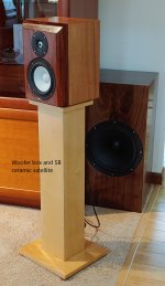
I am starting a new project. I am updating the satellite speakers of my system.
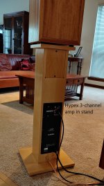
Last year I completed an active 3-way system with SB 12” woofer, SB 6” ceramic mid driver, and SB 1” ceramic dome tweeter. The Hypex amps located in the satellite stand, providing 250 W for the woofer, 250 W for the mid, and 100 W for the tweeter. The bass driver is mounted in its own cabinet, located a few feet behind the satellite. Crossovers are 200 Hz and 2 kHz. I have been astonished at how excellent the SB ceramic drivers have been. https://www.diyaudio.com/forums/multi-way/352767-active-3-hypex-sb.html
I always intended this system to be a learning experience, and I had always planned to build a more refined system later using better drivers. Originally, I was leaning toward ScanSpeak revelators or illuminators. I plan to keep the woofer boxes, and with the modular design with the amps in the stands and separate woofer boxes I can painlessly update the satellite speakers.
In October I purchased a pair of Satori textreme tweeters and a pair of Satori textreme 6” mid drivers. I made a set of measurements using a 24” x 24” test baffle, and later a prototype box. I posted the results here Link. https://www.diyaudio.com/forums/multi-way/343831-sb-acoustics-textreme-61.html post 608
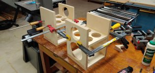
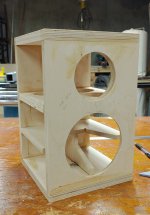
I have begun construction of the new satellite speakers. The new cabinets will be similar, but not quite identical to the old ones. Like the SB ceramic boxes, I do plan to build a double thick front baffle, 1.5 inch thick. The sides will be profiled with a 1.5 inch radius round-over bit, exactly like the SB ceramic boxes. This new build will use a 2 layer plywood baffle instead of a composite solid wood / plywood baffle. Before I did not have enough experience with veneer to confidently apply it over a curve, so I used solid wood. Now I know I can do it with veneer. The top edge will be chamfered at 45 degrees to a depth of 1.5 inch.
The SB ceramic box is 13" H x 10" W x 9" D. The new box will be 13.5" H x 10" W x 9.75" D. So slightly taller, slightly deeper. The arrangement of the internal braces will be different. I learned a lot while making the first cabinets ("learning" is code word for screw-ups). I attached my simulation of the baffle diffraction effect on the tweeter response.
I do not have any digital representations of the cabinet design (CAD or Sketchup). I did that kind of thing for 30 years and it feels too much like work... I like pencil and paper.
I value everyones input. As I optimize the filters, I will share my measurements, subjective opinions, and my thought process...
Last year I completed an active 3-way system with SB 12” woofer, SB 6” ceramic mid driver, and SB 1” ceramic dome tweeter. The Hypex amps located in the satellite stand, providing 250 W for the woofer, 250 W for the mid, and 100 W for the tweeter. The bass driver is mounted in its own cabinet, located a few feet behind the satellite. Crossovers are 200 Hz and 2 kHz. I have been astonished at how excellent the SB ceramic drivers have been. https://www.diyaudio.com/forums/multi-way/352767-active-3-hypex-sb.html
I always intended this system to be a learning experience, and I had always planned to build a more refined system later using better drivers. Originally, I was leaning toward ScanSpeak revelators or illuminators. I plan to keep the woofer boxes, and with the modular design with the amps in the stands and separate woofer boxes I can painlessly update the satellite speakers.
In October I purchased a pair of Satori textreme tweeters and a pair of Satori textreme 6” mid drivers. I made a set of measurements using a 24” x 24” test baffle, and later a prototype box. I posted the results here Link. https://www.diyaudio.com/forums/multi-way/343831-sb-acoustics-textreme-61.html post 608
I have begun construction of the new satellite speakers. The new cabinets will be similar, but not quite identical to the old ones. Like the SB ceramic boxes, I do plan to build a double thick front baffle, 1.5 inch thick. The sides will be profiled with a 1.5 inch radius round-over bit, exactly like the SB ceramic boxes. This new build will use a 2 layer plywood baffle instead of a composite solid wood / plywood baffle. Before I did not have enough experience with veneer to confidently apply it over a curve, so I used solid wood. Now I know I can do it with veneer. The top edge will be chamfered at 45 degrees to a depth of 1.5 inch.
The SB ceramic box is 13" H x 10" W x 9" D. The new box will be 13.5" H x 10" W x 9.75" D. So slightly taller, slightly deeper. The arrangement of the internal braces will be different. I learned a lot while making the first cabinets ("learning" is code word for screw-ups). I attached my simulation of the baffle diffraction effect on the tweeter response.
I do not have any digital representations of the cabinet design (CAD or Sketchup). I did that kind of thing for 30 years and it feels too much like work... I like pencil and paper.
I value everyones input. As I optimize the filters, I will share my measurements, subjective opinions, and my thought process...
Attachments

I love music
- By Franz77
- Introductions
- 1 Replies
Hello,
I've been involved with music for decades, actively in the past, but since I realized my talent didn't match my expectations , I prefer listening music. I enjoy my classical record collection and have switched to tube devices with full-range speakers in recent years. I hope my hearing lasts for a long time.
Best regards from Austria
Franz
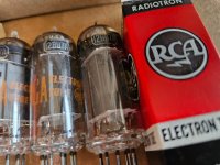
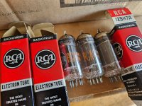
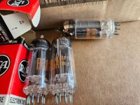
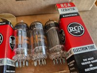
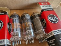
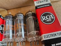
(3) NOS RCA 12BH7 12BH7A BLACK PLATE D Getter VACUUM TUBES 58455 -- NH USA --
$180 shipped in USA.
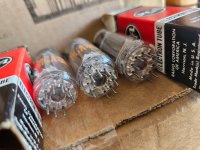
When I opened the package it FELT like the cardboard had never been opened before and the cardboard looks new.
As if the cardboard had never been bent past a certain point.
On both sides of the box the cardboard felt like it was never opened before. Do you know what I mean?
BUT THIS DOES NOT MEAN THEY ARE NEW.
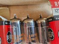
I have no way of testing them.
If you want to test them I am in Nashua, NH, USA.
(3) NOS RCA 12BH7 12BH7A BLACK PLATE D Getter VACUUM TUBES 58455 -- NH USA --
When I opened the package it FELT like the cardboard had never been opened before and the cardboard looks new.
As if the cardboard had never been bent past a certain point.
On both sides of the box the cardboard felt like it was never opened before. Do you know what I mean?
BUT THIS DOES NOT MEAN THEY ARE NEW.
I have no way of testing them.
If you want to test them I am in Nashua, NH, USA.
(3) NOS RCA 12BH7 12BH7A BLACK PLATE D Getter VACUUM TUBES 58455 -- NH USA --
Attachments
-
 20250429_111554.jpg495.2 KB · Views: 32
 -
 20250429_111603.jpg545.4 KB · Views: 29
 -
 20250429_111611.jpg612.4 KB · Views: 36
 -
 20250429_111614.jpg675.9 KB · Views: 35
 -
 20250429_111520.jpg629.9 KB · Views: 29
 -
 20250429_111540.jpg548.4 KB · Views: 34
 -
 20250429_111546.jpg540.6 KB · Views: 28
 -
 20250429_111548.jpg515.7 KB · Views: 35
Mele Overclock 4C mini PC - audio jack missing mass connection.
- By marigno
- Equipment & Tools
- 0 Replies
No HiFi here! Just Audio.
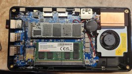
I bought 4 mini PC; all of them have the audio jack missing the connection to the mass when off. So if your speakers remain on, you hear an annoying hum.
When you turn on the PC, everything is fine, no more hum, if you check with an Ohm meter, the mass is now connected.
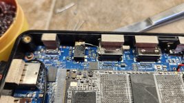
I solved this issue by connecting the audio mass to the mass of the mainboard with a short bridge. Very simple to do, but you must be very careful.
The operation doesn't need any explanation, just look at the pictures.
BTW, you better replace the SSD pad with one 1mm or 1.5mm thick, the stock one doesn't touch the bottom panel, so it is useless. I also removed the SSD label. The right pad stays with the bottom panel, not with the SSD, when you open the PC.
Cheers!
I bought 4 mini PC; all of them have the audio jack missing the connection to the mass when off. So if your speakers remain on, you hear an annoying hum.
When you turn on the PC, everything is fine, no more hum, if you check with an Ohm meter, the mass is now connected.
I solved this issue by connecting the audio mass to the mass of the mainboard with a short bridge. Very simple to do, but you must be very careful.
The operation doesn't need any explanation, just look at the pictures.
BTW, you better replace the SSD pad with one 1mm or 1.5mm thick, the stock one doesn't touch the bottom panel, so it is useless. I also removed the SSD label. The right pad stays with the bottom panel, not with the SSD, when you open the PC.
Cheers!
Attachments
For Sale Faital Pro HF10AK brand new pair
A pair (2 pcs) of Faital Pro HF10AK compression drivers for sale, including a matching pair (2 pcs) of Faital Pro STH100 horns, all are brand new in factory boxes. Drivers are 8 ohm version.
These need no introduction and are usually sold for alot more. I paid almost double my selling price. My loss is your gain and I want these to go to a good home.
Price is $390 shipped to the lower 48 US states.
These need no introduction and are usually sold for alot more. I paid almost double my selling price. My loss is your gain and I want these to go to a good home.
Price is $390 shipped to the lower 48 US states.
Help with tuning Onken enclosures
- By agrajag184
- Full Range
- 37 Replies
Hi all,
I was wondering if there is an old thread to point me to about how to customise the Onken / Fonken / etc. cabinets for different drivers, or if not, if somebody familiar with these can run me through the tuning process in general terms to make sure I'm not missing any considerations. I've read through and searched within a few Onken-related threads but not found anything comprehensive, but that doesn't mean it isn't out there. I've also definitely seen a few threads asking for advice about specific drivers lead to comments about appropriate box sizing but suggest that tuning will need to be done for them but can't find anywhere saying what this would entail.
Additionally, I've seen other threads saying that some designs for these behave like traditional ported enclosures and others function like aperiodic ones, and I'm not sure which the spreadsheet is for (presumably not aperiodic) nor if the design considerations are different for the other type.
I've been looking at the 2011 thread by Togril on creating an Onken for the Tang Band W5-1611SA, who seemed pretty happy with how their build went. I have the SAF model of the same driver sitting unused at the moment, so I thought I'd see if I came to the same sort of parameters before I start building anything (and I've got some fairly hard space constraints where I'll be putting these speakers that would mean that if I can find a way to design it to be marginally shallower that would help too).
I'm aware that there is a spreadsheet by one of the gurus of these speakers out there - the one by Cyr-Marc Debien from 2000 - and have been playing around with it. As far as I can see, the goal is to figure out an enclosure of about the right volume that is a sensible shape (with the usual considerations around ratios of length/width/height as for any other box) for the driver parameters whilst keeping enough box depth to allow for the required vent length that the calculator spits out. Some drivers will basically be unsuitable, and others can easily be fit into these constraints.
Where I'm getting confused is around decisions to do with vent dimensions - obviously making these wider or longer or changing the total number of them will dramatically change the required vent length, but I'm assuming they also impact sound in other ways so have no idea what I should be picking here as a starting point or what changes are generally likely to be 'safe' vs causing other issues.
Assuming this spreadsheet is a good way for me to design a box, I was also hoping to clarify some parameters / outputs in the spreadsheet itself that have me confused:
Firstly, why there are separate fields for "effective vent length" and "corrected effective vent length" and what is being corrected for? I'm assuming the corrected one is what I should be aiming to use in the final design, but wanted to make sure I'm using the right one, as in the tests I've done it is usually 10-20% different to the 'effective' one.
Secondly, what is the impact of changes to the "n=" / "Onken alignment" parameter on the final result? I'm assuming the 6.34 was what the original bass cabinets 60+ years ago (presumably designed by trial and error) ended up having once more modern simulation/calculation methods were applied to the old designs, and the 5.7 is a better compromise that has since been identified mathematically, but I'm not sure what it is compromising on or what changes up or down from this 'ideal' value are likely to do.
Finally, what influences the tuning frequency for the box/vents that this spits out, aside from driver parameters? Fb is one of the calculated values and can't be set by the user. With other vented enclosure calculators (or at least subwoofer ones) this is something that I believe the designer usually decides on along with box size, target Q etc, and these then are used along with the (fixed) driver parameters to determine the vent parameters, both area and length. Here it seems we are coming at this from the other side - based on a given vent area and driver parameters, a fixed 'optimal' volume, Fb, and Q are set, and the required vent length to achieve this is output. Is this understanding correct?
Hopefully someone can set me straight or otherwise point me towards resources that will help me figure this out on my own!
For Sale DBX Driverack Venu360, QSC GX7 amp NIB
I have for sale, brand new in original factory boxes, never used, mounted whatsoever. They're NOT B-stock or gray market. Purchased locally brand new from factory authorized dealers.
DBX Driverack Venu 360 loudspeaker processor (96k sample rate, with AES/spdif inputs), brand new in original box with manual, sells regularly online for about $1000. Asking $600
QSC GX7 2 ch professional power amplifier, 800W/ch @ 8 ohm, 1200/ch @ 4 ohm. Very clean sounding, reliable, light weight. Brand new, sealed in factory box. Sells regularly online for about $900. Asking $500
Both units priced for quick sale at almost half of the regular selling price. Also advertised locally for sale in my area.
Shipping only to lower 48 states - pls ask me for a quote.
Send me a PM for more info if you're interested.
Electronics enthusiast from France
- By ti-jean
- Introductions
- 1 Replies
Hi,
I'm a high-end audio enthusiast, interested by modding, tweaking, and restoring things. I love vintage speakers and amplifiers, have a tiny collection of cool old gears (cabasse sampan 311, celestion ditton 33, jmlab 913, luxman amps, Sansui amps) and some modern stuff (hypex, topping dac, adam audio active speakers).
I've done some mic tweaking too, DIY builds. I'm a musician and a videographer, so I use a lot of my builds for work.
I'm based in the south west of france, near Pau, and i'm a long-time reader of diyAudio forum.
North Star Supremo intro
- By DannyJag
- Introductions
- 1 Replies
Hi all, I own a DAC North Star Supremo. I was struggling to get an ASIO driver for Windows 10. Lucky me got support though the provider is not in business anymore so I found here a thread on it and I will share the driver for anyone who is interested
Attachments
WTB Sprague black 0,1uF 600V caps needed
I am in the need of 20 pieces to restore my vintage gear. Also would need 0.047 uF/600V. Maybe you have that many in your drawer or just few to let them sold. Thanks.
Sabourin Speaker
- By Olco
- Introductions
- 6 Replies
Hello,
I have a question about the Sabourin Speaker from Troy Crowe.
The horn consists of 3 stages. The 1st has an 15,5° angel and 47,2° on the sides.
Can anyone please explain why that is 47,2° and not 45°?
Fr.gr.
Olco
I have a question about the Sabourin Speaker from Troy Crowe.
The horn consists of 3 stages. The 1st has an 15,5° angel and 47,2° on the sides.
Can anyone please explain why that is 47,2° and not 45°?
Fr.gr.
Olco
NAP 250 clone V3.0
- By cristobool
- Solid State
- 0 Replies
Hello everyone, I just finished a new NAP 250 clone.
I had already made two other versions of the NAP 250, but as a hobbyist, I made mistakes and learned along the way how to correct them and tune this amplifier, thanks in part to other members of the diyAudio community.
My previous clone can be seen here:
So, I'll present my new version here. I can provide my files for those who wish to build one and/or conduct further tests and delve deeper into the design of a NAP250 clone.
This time, it's not a truly original clone; the objectives were as follows:
- Find other transistor references that could be used for the NAP
that were both of better quality to improve audio quality and more robust.
- Switch to plastic transistors for simpler and less expensive construction.
- Make the amplifier more stable and able to handle low loads (1 ohm for a musical signal).
- Integrate the NAP and NAPS on the same PCB, with full alignment of the power transistors and drivers to place them on the same heatsink.
-Place the VBE on the heatsink for better control of the output stage bias.
-Improve the ground plane, which was done with the help of jpk73.
-Make an effort to minimize the design and reduce the final cost.
-Add a regulator for the amplifier's input stages, which was done thanks to the work of jpk73. I used his schematic. The goal was to improve sound quality.
-Add speaker protection, which was made possible thanks to Bigun's TGM10 design. This protection was modified by jpk73 based on suggestions from various forum members; mine is based on jpk73's schematic.
-After simulating in Ltspice, I slightly modified some values to achieve a slight improvement in the phase and gain margin while maintaining the same THD. These are the values Naim has used on some NAP140s.
Once finished, I encountered a NAPS stability issue with the modifications I had made. I was able to resolve this issue with the help of as_audio:
I added a Hypex module that does softstart/standby mode and thermal protection.
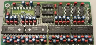
the main PCB with NAP/NAPS :

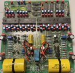
the front regulator base on LM317/337 :

The HP protection PCB TGM 10 :

square wave signal 100 mv 10 Khz in on a capacitive load of 1uF with 6,8 ohms with a NAPS rail (up trace is the output signal, down trace is the NAPS rail)

square wave signal 100 mv 10 Khz in on a capacitive load of 1uF with 6,8 ohms with a front regulator rail

square wave signal 1 Volt 10 Khz in on a load of 6,8 ohms with a NAPS rail

Sinusoidale wave 2,6 volts 1 kHz load 6,8 ohms with a NAPS rail :


I had already made two other versions of the NAP 250, but as a hobbyist, I made mistakes and learned along the way how to correct them and tune this amplifier, thanks in part to other members of the diyAudio community.
My previous clone can be seen here:
So, I'll present my new version here. I can provide my files for those who wish to build one and/or conduct further tests and delve deeper into the design of a NAP250 clone.
This time, it's not a truly original clone; the objectives were as follows:
- Find other transistor references that could be used for the NAP
that were both of better quality to improve audio quality and more robust.
- Switch to plastic transistors for simpler and less expensive construction.
- Make the amplifier more stable and able to handle low loads (1 ohm for a musical signal).
- Integrate the NAP and NAPS on the same PCB, with full alignment of the power transistors and drivers to place them on the same heatsink.
-Place the VBE on the heatsink for better control of the output stage bias.
-Improve the ground plane, which was done with the help of jpk73.
-Make an effort to minimize the design and reduce the final cost.
-Add a regulator for the amplifier's input stages, which was done thanks to the work of jpk73. I used his schematic. The goal was to improve sound quality.
-Add speaker protection, which was made possible thanks to Bigun's TGM10 design. This protection was modified by jpk73 based on suggestions from various forum members; mine is based on jpk73's schematic.
-After simulating in Ltspice, I slightly modified some values to achieve a slight improvement in the phase and gain margin while maintaining the same THD. These are the values Naim has used on some NAP140s.
Once finished, I encountered a NAPS stability issue with the modifications I had made. I was able to resolve this issue with the help of as_audio:
I added a Hypex module that does softstart/standby mode and thermal protection.
the main PCB with NAP/NAPS :
the front regulator base on LM317/337 :
The HP protection PCB TGM 10 :
square wave signal 100 mv 10 Khz in on a capacitive load of 1uF with 6,8 ohms with a NAPS rail (up trace is the output signal, down trace is the NAPS rail)
square wave signal 100 mv 10 Khz in on a capacitive load of 1uF with 6,8 ohms with a front regulator rail
square wave signal 1 Volt 10 Khz in on a load of 6,8 ohms with a NAPS rail
Sinusoidale wave 2,6 volts 1 kHz load 6,8 ohms with a NAPS rail :
Looking for North Star DAC drivers for Windows
- By kilohertz
- Digital Line Level
- 13 Replies
I have spent 2 days searching the web for USB-DSD USB drivers for my new to me North Star Incanto DAC. Their website is gone and wayback machine only has one ZIP file which doesn't install drivers on windows (at least on my computers, fails every time)
Does anyone out there have the driver package for North Star or whatever I might need to get USB working on this DAC?
Look forward to any help.
Thanks!
PS Using Foobar-2000 as a player in WIN 7 if that makes any difference
Does anyone out there have the driver package for North Star or whatever I might need to get USB working on this DAC?
Look forward to any help.
Thanks!
PS Using Foobar-2000 as a player in WIN 7 if that makes any difference
For Sale Ultimate low power class A amplifier – my way
A great little amplifier from @tombo56 and details here - https://www.diyaudio.com/community/...te-low-power-class-a-amplifier-my-way.404147/ sounds excellent with high sensitivity speakers like my Klipsch Forte. I was using with a 12vac transformer paired with Prasi LT4230 regulator based CRC psu. Some pics of my build are also documented in the same thread.
Expecting $175 including CONUS shipping. Few pics of as-is unit for reference. High quality parts from Mouser/Digikey the laterals from Profusion PLC.


Expecting $175 including CONUS shipping. Few pics of as-is unit for reference. High quality parts from Mouser/Digikey the laterals from Profusion PLC.
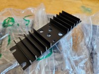
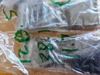
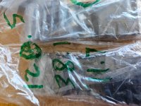
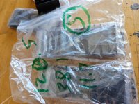
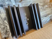
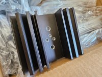
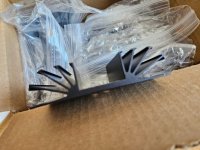
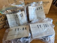
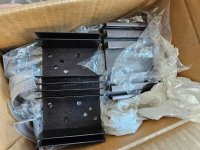
Amplifier/transistor HEATSINKS -- TRIAD TRANSFORMER TY-84 TY-81 TY-69S TY-101 -- NH USA -- amp
Best offer.
Please post in thread in possible.
Some dimensions are in the pics, in mm.
I can post more pics later.
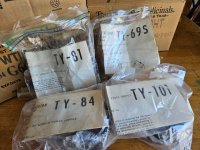
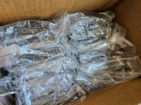
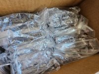
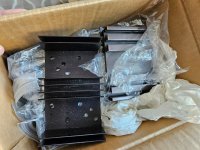
Amplifier/transistor HEATSINKS -- TRIAD TRANSFORMER TY-84 TY-81 TY-69S TY-101 -- NH USA -- amp
Please post in thread in possible.
Some dimensions are in the pics, in mm.
I can post more pics later.
Amplifier/transistor HEATSINKS -- TRIAD TRANSFORMER TY-84 TY-81 TY-69S TY-101 -- NH USA -- amp
Attachments
-
 20250424_103202.jpg630.1 KB · Views: 24
 -
 20250424_103208.jpg371.9 KB · Views: 23
 -
 20250424_103230.jpg483.3 KB · Views: 26
 -
 20250424_103231.jpg488.5 KB · Views: 29
 -
 20250424_103232.jpg528.2 KB · Views: 31
 -
 20250424_103318.jpg524.8 KB · Views: 23
 -
 20250424_103319.jpg602 KB · Views: 28
 -
 20250424_103326.jpg516.6 KB · Views: 28
 -
 20250424_103442(0).jpg667.5 KB · Views: 26
 -
 20250424_103442.jpg650.2 KB · Views: 28
 -
 20250424_103514.jpg691.7 KB · Views: 29
 -
 20250424_103515.jpg782.5 KB · Views: 30
 -
 20250424_103531.jpg599.3 KB · Views: 29
 -
 20250424_103532.jpg648.9 KB · Views: 28
For Sale AD1862N-J New Old Stock DAC chips
SOLD OUT
Have two pairs of AD1862N-J graded chips. Totally new and unused - not even inserted into sockets before.
A pair of the chips + shipping to you registered & trackable = Singapore Dollars 120 (approximately US$92)
Payment by Paypal FF only please. If you are unable to use this mode of payment, I apologise that I have no other ways to accept the funds.
Thanks.
What are these capacitors ???
Hi - I want to replace these ageing caps in my tube preamp
 - not sure of the values - 1 of them says '100M + 100M' and the other 2 say '32M + 32M' - any ideas ???
De-magnetization control of large inductor
- By zigzagflux
- Power Supplies
- 13 Replies
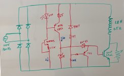
Not an audio circuit, but given the knowledge base here with large inductors, tubes, and high voltage, I am throwing out an idea for comments.
The attached is a circuit I am thinking about for fast demag of a large inductance. The AC source is continuously variable from 0-100V although it typically will run between 10 and 30. When the system is active, DC current flows through the inductor, and the IGBT must be switched on. When the system shuts off, AC power drops to zero, and the rectifier free wheels the inductance. At that point, polarity across the rectifier switches, and the IGBT must shut off quickly. This applies the nonlinear resistor in series with the inductor. L/R increases, and the magnetic energy is quickly dissipated vs simply allowing it to freewheel through the internal resistance.
The green circuit is not really subject to change. The red is what I am toying around with. I would like to keep things as passive as possible - no DC/DC converters or big charge pumps. A few of my current challenges:
a. At low voltages, I struggle to get the current sources up, as well as the problem of not having sufficient voltage to turn the IGBT on. Fortunately, switching frequency is extremely low, so I am not overly concerned with slow rise times. Fast fall time is a benefit.
b. Trying to keep watt dissipation low - the red circuit will end up being epoxy potted, with maybe one small heatsink sticking out.
c. Voltages can get pretty high (still working out actual maximums), so my transistor choices are limited.
d. Debating if the active Miller clamp is really necessary.
I probably have more thoughts as this develops, but wanted some extra eyes to put a sanity check on this.
Attachments
Requesting Expert Feedback on Custom 4-Way Accuton Crossover Design
- Multi-Way
- 65 Replies
안녕하세요 여러분.
모두 잘 지내고 계시길 바랍니다.
저는 4방향 패시브 크로스오버 네트워크를 설계했으며, 제 디자인에 대한 전문가의 피드백과 제안을 부탁드리고 싶습니다.
다음은 시스템에 대한 간략한 개요입니다:
드라이버 유닛
- 트위터: Accuton C25-6-158
- 중간 범위: Accuton C90-6-079
- 미드우퍼: Accuton C173-6-191E
- 우퍼: Accuton C173-6-191E (second unit)
- 우퍼: 370Hz 이하
- 미드우퍼: 390Hz ~ 707Hz
- 중간 범위: 681Hz ~ 2.8kHz (매끄러운 핸드오프)
- 트위터: 2.8kHz 이상의 자연스러운 확장
디자인 접근 방식
- 크로스오버 포인트는 고전적인 LC 필터 이론을 기반으로 계산되었습니다.
- 기울기, 임피던스 보정(조벨 네트워크) 및 구성 요소 값의 미세 조정은 AI(ChatGPT) 상담을 통해 지원되었습니다.
- 부드러운 주파수 응답, 위상 일관성, 왜곡 최소화 및 고급 성능 특성을 달성하는 데 중점을 두었습니다.
추가 참고 사항
- 증폭기의 임피던스 평탄화와 더 나은 부하 동작을 보장하기 위해 필요한 경우 Zobel 네트워크를 적용했습니다.
- 목표는 정밀도, 자연스러운 음색, 그리고 오디오 애호가 수준의 해상도를 결합한 시스템을 만드는 것입니다.
시간과 전문 지식을 제공해 주셔서 대단히 감사합니다!
Tung-Sol KT170 tube question
- By FSHZ42
- Tubes / Valves
- 4 Replies
I'd like to order (2) matched pair of these Tung-Sol KT170 tubes. I have heard that when they first came out, they had some issues and then supposedly fixed whatever it was that was causing problems. I'm not certain of this, just relaying what I read and heard.
My question is does anyone know where I could buy some that would have the latest batches from Tung-Sol? I've also read where they do take a rather long time to settle/burn-in?
Thanks in advanced!
My question is does anyone know where I could buy some that would have the latest batches from Tung-Sol? I've also read where they do take a rather long time to settle/burn-in?
Thanks in advanced!
Is this audiophilia?
- By pl802
- The Lounge
- 2 Replies
Let's talk about the art of using Multiple Woofers
The classic tower speaker. We all know it. It is burned into our brains. It stands well off the floor. It has impressive looking multiple woofer in a line going up. It impresses friends. It sells loudspeakers. An absolute staple in the hifi world. If you ask the average person on the street to draw you a picture of a hifi speaker I'll bet my speaker collection that they draw sketch out a tower on that piece of paper.
So lets discuss the dark art of multiple woofers. I am going to ask some questions along the way. For this we will focus on the 500hz and down end of the woofers. Just to simplify things a bit
1. Multiple woofers because the sensitivity of woofers is, in general, lower than the mids and the highs.
We have all padded down a tweeter. We have all experienced the loss of sensitivity because of those resistors. Everyone knows that more speakers equals more louder. I hear it is +3db. I have a question though. Lets take 2 woofers. Specifically, lets take two 8 ohm 6.5" woofers. Dayton RS150-8 for example. I probably wouldn't ever use these but its easy for me to sim this.
Lets look at a single woofer and lets say we are only going to use it from nill up to 500 hz.

We have about 89 db sensitivity there. Lowest impedence is 6.0 ohm.
Cool, we have a baseline. Now, lets add a second woofer. We will wire this one in paralell

Alright, now we have jumped up to about 95 db sensitivity. +6db. We are now down to 3 ohm
Let's now wire that woofer in series.

Alright, we are back where we started. 89 db except now we have a 13 ohm lowest impedence. So, what happened to all of sensitivity increase?
It went out with impedence is my guess. Then was ou6r previous +6db gain from the impedence as well? I do not know.
Do we only gain our +6 db when wire in paralell or are we getting +3db from the dual speakers and +3db from the impedence?
Lucky for us, there is a 4 ohm version of this driver. Lets compare a single 4 ohm and series 4 ohm.
91.7 db, 2.8 ohm lowest impedence Same in series, 91.7, 2.8 ohm


Now, we can decipher that adding another woofer in series doesn't make it play louder. However, two woofers with the same impedence as one woofer gives us a +3db sensitivity.
The two in parallel with a combined impedence of 4 ohm is about +3db louder than a single driver with an impedence of 4 ohm.
Is this how this works then?
2. Crossover values diminish with lower woofers
Lets take a look at inductor values
Lets cross at around 250 with an 8 ohm. 3 mh is needed. 43 uf cap. You see we are crossing 90db at 204 hz with these values

Now, same values with a 4 ohm driver. We see we would need higher values of components to cross as low as the 4 ohm driver. We are crossing 90 at around 300 hz now.

So, from this we need higher values with an 8 ohm driver. So what if we use two 8 ohm drivers in paralell.
95 db at 109 hz. Cool, this looks nicer. Look at all that low end gain and we get to use lower values for components

Alright, one more time but in series.
Booooo, well that stinks. Now we end up with a hump where we don't want it and it looks like we have actually lost high end extension
If we do try to use the low end here we would need huge components and we get no gain. Lose lose situation as far as I can tell.

Ok, so with this, I have concluded that there are senstivity benefits, low end extension benefits, and lower value component values if we use multiple woofer but ONLY if we use them in parallel. Am I on the right track here? I am not seeing why anyone would wire them in series other than to save their amplifier because it has an impedence limitation and all they have lying around are lower impedence drivers.
I am seeing how we get more low end extension with two drivers. At least in theory
3. More Cone area = More Bass
Now this I have heard all my life. However, when I start to run this through the ringer of physics, I am not seeing it play it out the way I would expect.
Lets toss a single 10" woofer, a single 12" woofer, and dual 10" woofers into WinISD.
5' box for the single 10, 6' for the single 12, 10' for the dual 10"
 We have wayyyyyy more cone area with the dual 10 yet, basically no more bass extension even though we doubled the box size. Not only this but the single 12 still hits harder. I see this across the board with any driver I have ever tried to sim in whatever combination. It doesn't matter. Never does multiple smaller drivers hit as low as a single large cone. Never. I could sim drivers all night long (and I have) and not see this standard change.
So, is WINISD completely off base? I find that hard to believe because I have used it in conjunction with Hornresp and have had it spit out eerily accurate results in the world I reside.
Does more cone area just mean louder? It doesn't mean lower?
4. Floor Bounce and Diffraction
These two, in my mind, are combined. Far as I can tell, the floor and the diffraction are two metrics that combine to give you a low end response. The baffle step takes away, and, if done right, the floor can give back. Or the floor can take away. Or the floor can take away AND give back. Ahhhh, the wizardry begins.
I understand these the least. Or rather, I have done the least testing with these. I fully understand the physics of what is happening.
I am a visual person so lets do some examples. I just learned how to do this so let me know if I am doing this entirely wrong. Which I think I might be.
6" woofer at 20" heigh on a 10" baffle where you'd normally place a single woofer close to mid.
We lose about 6 db off low end to the baffle.

Then we gain some from the floor at 20".

Then we get the summed response and we end up with that stupid dip at 100 hz that I have experienced in a build and very much annoys me. Though we still gain some bass so thats cool.

Lets slap a second woofer on the floor. Right down below. I have seen some speakers designed like this and honestly do not understand how they get away with the phase issue unless they are crossing very low like 120hz or something.

Doesn't matter! We still get a stupid dip at 100 hz.
Questions:
Do I sum two woofers together in this simulator?
How do you avoid the 100 hz dip? Do you need to go up much higher from the floor? WMTMW style?
Is there any way to apply this to a simulated response just for design purposes and factor this in?
So lets discuss the dark art of multiple woofers. I am going to ask some questions along the way. For this we will focus on the 500hz and down end of the woofers. Just to simplify things a bit
1. Multiple woofers because the sensitivity of woofers is, in general, lower than the mids and the highs.
We have all padded down a tweeter. We have all experienced the loss of sensitivity because of those resistors. Everyone knows that more speakers equals more louder. I hear it is +3db. I have a question though. Lets take 2 woofers. Specifically, lets take two 8 ohm 6.5" woofers. Dayton RS150-8 for example. I probably wouldn't ever use these but its easy for me to sim this.
Lets look at a single woofer and lets say we are only going to use it from nill up to 500 hz.
We have about 89 db sensitivity there. Lowest impedence is 6.0 ohm.
Cool, we have a baseline. Now, lets add a second woofer. We will wire this one in paralell
Alright, now we have jumped up to about 95 db sensitivity. +6db. We are now down to 3 ohm
Let's now wire that woofer in series.
Alright, we are back where we started. 89 db except now we have a 13 ohm lowest impedence. So, what happened to all of sensitivity increase?
It went out with impedence is my guess. Then was ou6r previous +6db gain from the impedence as well? I do not know.
Do we only gain our +6 db when wire in paralell or are we getting +3db from the dual speakers and +3db from the impedence?
Lucky for us, there is a 4 ohm version of this driver. Lets compare a single 4 ohm and series 4 ohm.
91.7 db, 2.8 ohm lowest impedence Same in series, 91.7, 2.8 ohm
Now, we can decipher that adding another woofer in series doesn't make it play louder. However, two woofers with the same impedence as one woofer gives us a +3db sensitivity.
The two in parallel with a combined impedence of 4 ohm is about +3db louder than a single driver with an impedence of 4 ohm.
Is this how this works then?
2. Crossover values diminish with lower woofers
Lets take a look at inductor values
Lets cross at around 250 with an 8 ohm. 3 mh is needed. 43 uf cap. You see we are crossing 90db at 204 hz with these values
Now, same values with a 4 ohm driver. We see we would need higher values of components to cross as low as the 4 ohm driver. We are crossing 90 at around 300 hz now.
So, from this we need higher values with an 8 ohm driver. So what if we use two 8 ohm drivers in paralell.
95 db at 109 hz. Cool, this looks nicer. Look at all that low end gain and we get to use lower values for components
Alright, one more time but in series.
Booooo, well that stinks. Now we end up with a hump where we don't want it and it looks like we have actually lost high end extension
If we do try to use the low end here we would need huge components and we get no gain. Lose lose situation as far as I can tell.
Ok, so with this, I have concluded that there are senstivity benefits, low end extension benefits, and lower value component values if we use multiple woofer but ONLY if we use them in parallel. Am I on the right track here? I am not seeing why anyone would wire them in series other than to save their amplifier because it has an impedence limitation and all they have lying around are lower impedence drivers.
I am seeing how we get more low end extension with two drivers. At least in theory
3. More Cone area = More Bass
Now this I have heard all my life. However, when I start to run this through the ringer of physics, I am not seeing it play it out the way I would expect.
Lets toss a single 10" woofer, a single 12" woofer, and dual 10" woofers into WinISD.
5' box for the single 10, 6' for the single 12, 10' for the dual 10"
So, is WINISD completely off base? I find that hard to believe because I have used it in conjunction with Hornresp and have had it spit out eerily accurate results in the world I reside.
Does more cone area just mean louder? It doesn't mean lower?
4. Floor Bounce and Diffraction
These two, in my mind, are combined. Far as I can tell, the floor and the diffraction are two metrics that combine to give you a low end response. The baffle step takes away, and, if done right, the floor can give back. Or the floor can take away. Or the floor can take away AND give back. Ahhhh, the wizardry begins.
I understand these the least. Or rather, I have done the least testing with these. I fully understand the physics of what is happening.
I am a visual person so lets do some examples. I just learned how to do this so let me know if I am doing this entirely wrong. Which I think I might be.
6" woofer at 20" heigh on a 10" baffle where you'd normally place a single woofer close to mid.
We lose about 6 db off low end to the baffle.
Then we gain some from the floor at 20".
Then we get the summed response and we end up with that stupid dip at 100 hz that I have experienced in a build and very much annoys me. Though we still gain some bass so thats cool.
Lets slap a second woofer on the floor. Right down below. I have seen some speakers designed like this and honestly do not understand how they get away with the phase issue unless they are crossing very low like 120hz or something.
Doesn't matter! We still get a stupid dip at 100 hz.
Questions:
Do I sum two woofers together in this simulator?
How do you avoid the 100 hz dip? Do you need to go up much higher from the floor? WMTMW style?
Is there any way to apply this to a simulated response just for design purposes and factor this in?
Attachments
WTB GlassWare Aikido Cathode Follower (noval) PCB, Tube-I-Zator PCB
- By Michael G.
- Swap Meet
- 0 Replies
Hi,
as I am too late for both parties, I'm looking now for the two PCBs:
Please, consider that I live in Germany.
I'm not very much interested in a kit, but don't hesitate to write me, even if you'd like to sell an assembled board.
Thank you!
as I am too late for both parties, I'm looking now for the two PCBs:
- GlassWare Aikido Cathode Follower aka ACF from John Broskie - either "classic" or 12Vac, noval (!) tube buffer
- Tube-I-Zator (or Tubizator) PCB - SRPP I/V for TDA154x
Please, consider that I live in Germany.
I'm not very much interested in a kit, but don't hesitate to write me, even if you'd like to sell an assembled board.
Thank you!
Kia Ora from New Zealand
- By zer0t0her0
- Introductions
- 3 Replies
Kia Ora (greetings) from New Zealand.
I enjoy modding and restoring audio gear.
I have b&w cm7 speakers, rotel pre and power amps, and various other gear from manufacturers like Enlightened audio designs, Sansui, Luxman, Assemblage, Denon, Arcam etc.
I enjoy modding and restoring audio gear.
I have b&w cm7 speakers, rotel pre and power amps, and various other gear from manufacturers like Enlightened audio designs, Sansui, Luxman, Assemblage, Denon, Arcam etc.
Crossover Comments Please
Over the past few months I have been sorting out my measurement techniques using the loopback scheme and have built a REW impedance rig.
Apologies this may be a long post.
Drivers - SB WO24P-4 woofer, Morel EM1308 Dome Mid, Morel ET448 Tweeter.
Box - Approx 40L sealed and medium stuffed with polyester toy stuffing. (re-purposed Akai SW125 box)
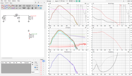
I finally got round to making a set of measurement the other day and have tweaked my active crossover to a point where I like the sound and theoretically it models well. The caveat here is that the room I have done the measurements in is not very large and has furniture in so quite a few reflections sothey are not perfect and have been smoothed. Measurement were taken at 1m at tweeter height and around 85dB loudness (roughly calibrated against mobile phone dB meter).
I took measurement from -90 to +90 degs for each of the drivers without moving the mic (note the Tweeter and Mid are both domes and so have protection capacitors, measurements taken with and with out these in place). I took nearfield for the woofer 1cm from the centre dust cap (sealed enclosure) and then impedance of each of the drivers in the box (with and without protection caps just for interest).

The results for the woofer seemed to suggest I am on the right track. The nearfield looks to be close to a Max Flat alignment which is what I was after. The 1m measurement aligns Ok with the manufacturer data and shows the baffle step below around 350hz (360mm wide baffle). Also the Impedance curve matches the Winisd output almost identically (peak : 32ohms at 47hz). So the box look pretty good for the WO24P-4 woofer.

I have been running a Minidsp Nanodigi crossover for a while and have had great fun playing with different slope filters and arrangements and also comparing it to crossover designs in VituixCad that seem to align quite well.
A quick check on the step/impulse response delays between the tweeter and the mid./woofer seem plausible at approx 5mm for tweeter to mid and 75mm for tweeter to woofer. So reference feedback seems to be working and has now embedded the acoustic offset into the phase measurements.
I then loaded up the +cap tweeter/mid and woofer measurements into VituixCad and played around with a few different designs with different slopes for an active crossover, these ranged from BW6 to LR24 in various combinations. The aim was to get a fairly flat on axis frequency response, align phase of each driver as close as I could (min 1 octave either side of the crossover point) and then have an in-room response that tried to follow a slope of 0.9dB/octave (or 6dB form 100hz to 10khz). Note, I did not merge the nearfield so it has room bass reflections under around 300hz.
Without documenting all of the various trials and errors, I settled on the following scheme that seems to meet most of the requirements quite well. To me this sounded the best subjectively, it has a fairly large soundstage with decent separation between the instruments and has a natural and lifelike presentation. I could stand the vocals being a little more forward but this is the only minor criticism. Bass is plentiful in my 10ft x 10ft x 8.5ft [ceiling] room with the speakers pushed a little into the corners.

So, having got a sound I liked I then tried to replicate this with a passive crossover (using the -cap measurements and measured impedances)........and this is what I came up with.
 and with mid Inverted
This is basically a simple LR12 electrical topology which ends up being an acoustic LR24 on the woofer/mid crossover and LR12 on the Mid/Tweeter. There is a damping resistor on the mid with a shaping resistor in the low pass parallel leg. There is an L-pad on the tweeter. The resulting impedence curve looks manageable for most modern amps with a low of 3.2ohms at 110hz but is definitely a 4ohm design.
Now the bit where I would like a bit of critique of what I have done to tame the rising frequency response of the tweeter that is seen in many Morel units. I added a small inductor in series to tip over the curve at around 8Khz and then added a notch at around 10khz. This seems to flatten things off nicely but is having and inductor in series in a tweeter circuit a good idea and will it affect the sound negatively?
In general think the p[assive version matches the design aims and the active system fairly well.
Finally, before I splash some cash on crossover components to see if this scheme sounds as good as the active version (would be happy if it did), for the woofer inductor is it Ok to use a 1mm/18awg iron core coil or do I need to go 14awg Air coil and also for the 100uF capacitor is something like a Jantzen eLeCap 5% Electrolytic Bipolar Capacitor Ok to use or again do I need to go for a Jantzen CrossCap? Just trying to keep the cost sensible at the moment until I know it is Ok. The rest of the Caps are affordable using Jantzen Standard and the coils will be 18AWG Air Coils.
Anyway, congratulations for getting to the end, and thanks in advance for any comments left. Everyday is a school day for me!
Apologies this may be a long post.
Drivers - SB WO24P-4 woofer, Morel EM1308 Dome Mid, Morel ET448 Tweeter.
Box - Approx 40L sealed and medium stuffed with polyester toy stuffing. (re-purposed Akai SW125 box)
I finally got round to making a set of measurement the other day and have tweaked my active crossover to a point where I like the sound and theoretically it models well. The caveat here is that the room I have done the measurements in is not very large and has furniture in so quite a few reflections sothey are not perfect and have been smoothed. Measurement were taken at 1m at tweeter height and around 85dB loudness (roughly calibrated against mobile phone dB meter).
I took measurement from -90 to +90 degs for each of the drivers without moving the mic (note the Tweeter and Mid are both domes and so have protection capacitors, measurements taken with and with out these in place). I took nearfield for the woofer 1cm from the centre dust cap (sealed enclosure) and then impedance of each of the drivers in the box (with and without protection caps just for interest).
The results for the woofer seemed to suggest I am on the right track. The nearfield looks to be close to a Max Flat alignment which is what I was after. The 1m measurement aligns Ok with the manufacturer data and shows the baffle step below around 350hz (360mm wide baffle). Also the Impedance curve matches the Winisd output almost identically (peak : 32ohms at 47hz). So the box look pretty good for the WO24P-4 woofer.
I have been running a Minidsp Nanodigi crossover for a while and have had great fun playing with different slope filters and arrangements and also comparing it to crossover designs in VituixCad that seem to align quite well.
A quick check on the step/impulse response delays between the tweeter and the mid./woofer seem plausible at approx 5mm for tweeter to mid and 75mm for tweeter to woofer. So reference feedback seems to be working and has now embedded the acoustic offset into the phase measurements.
I then loaded up the +cap tweeter/mid and woofer measurements into VituixCad and played around with a few different designs with different slopes for an active crossover, these ranged from BW6 to LR24 in various combinations. The aim was to get a fairly flat on axis frequency response, align phase of each driver as close as I could (min 1 octave either side of the crossover point) and then have an in-room response that tried to follow a slope of 0.9dB/octave (or 6dB form 100hz to 10khz). Note, I did not merge the nearfield so it has room bass reflections under around 300hz.
Without documenting all of the various trials and errors, I settled on the following scheme that seems to meet most of the requirements quite well. To me this sounded the best subjectively, it has a fairly large soundstage with decent separation between the instruments and has a natural and lifelike presentation. I could stand the vocals being a little more forward but this is the only minor criticism. Bass is plentiful in my 10ft x 10ft x 8.5ft [ceiling] room with the speakers pushed a little into the corners.
So, having got a sound I liked I then tried to replicate this with a passive crossover (using the -cap measurements and measured impedances)........and this is what I came up with.
and with mid Inverted This is basically a simple LR12 electrical topology which ends up being an acoustic LR24 on the woofer/mid crossover and LR12 on the Mid/Tweeter. There is a damping resistor on the mid with a shaping resistor in the low pass parallel leg. There is an L-pad on the tweeter. The resulting impedence curve looks manageable for most modern amps with a low of 3.2ohms at 110hz but is definitely a 4ohm design.
Now the bit where I would like a bit of critique of what I have done to tame the rising frequency response of the tweeter that is seen in many Morel units. I added a small inductor in series to tip over the curve at around 8Khz and then added a notch at around 10khz. This seems to flatten things off nicely but is having and inductor in series in a tweeter circuit a good idea and will it affect the sound negatively?
In general think the p[assive version matches the design aims and the active system fairly well.
Finally, before I splash some cash on crossover components to see if this scheme sounds as good as the active version (would be happy if it did), for the woofer inductor is it Ok to use a 1mm/18awg iron core coil or do I need to go 14awg Air coil and also for the 100uF capacitor is something like a Jantzen eLeCap 5% Electrolytic Bipolar Capacitor Ok to use or again do I need to go for a Jantzen CrossCap? Just trying to keep the cost sensible at the moment until I know it is Ok. The rest of the Caps are affordable using Jantzen Standard and the coils will be 18AWG Air Coils.
Anyway, congratulations for getting to the end, and thanks in advance for any comments left. Everyday is a school day for me!
Travel speaker 2.0: Less speaker = more gooder?
I'm always on the lookout for teeny speaker of ridiculous quality and a couple years back I spied these bad boys:

These i believe were called the Maximus 7s. I bought them Dan P. of CSS at a bargain price of $600. They sounded great as is....but I had other plans 😈.


These i believe were called the Maximus 7s. I bought them Dan P. of CSS at a bargain price of $600. They sounded great as is....but I had other plans 😈.
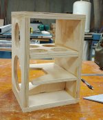
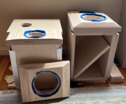
Building the Ellam FLEX by Troels Gravesen
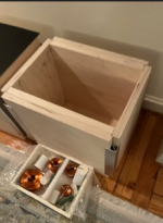
I’ve started building the Ellam FLEX two-way. Thanks for the reassurance that 400V caps can be used in the crossover design. I’ve sourced Mundorf MCAP 400V DC polypropylene caps with the same µF values as shown in the schematic, instead of the much more expensive Superior Z.
Cabinet work is underway — I’ve done everything so far without power tools, except for a basic IKEA cordless drill, and I don’t even have clamps. The crossover is quite big and heavy, so I’ve decided to keep it outside the box. I’ll share photos soon. Looking forward to any tips or feedback from others who’ve built this design!
Cabinet work is underway — I’ve done everything so far without power tools, except for a basic IKEA cordless drill, and I don’t even have clamps. The crossover is quite big and heavy, so I’ve decided to keep it outside the box. I’ll share photos soon. Looking forward to any tips or feedback from others who’ve built this design!
Attachments
Mark Levinson 433 voltage conversion
- By Rawi
- Solid State
- 0 Replies
Hi,
I have a 110V 60Hz Mark Levinson 433 three channel amplifier that I need to convert to 220V 50Hz. I succeeded in obtaining the propper IC chip from Mark Levinson but they don't have the corresponding PCB.
The PCB is simply a jumper that I could build easily. Would anyone have the graciousness of helping me with the propper jumper configuration? Or maybe a picture of the jumper PCB for 220V? 🙏🙏🙏😊
I am a high end fan
- By Rawi
- Introductions
- 2 Replies
Hi,
I have a 110V 60Hz Mark Levinson 433 three channel amplifier that I need to convert to 220V 50Hz. I succeeded in obtaining the propper IC chip from Mark Levinson but they don't have the corresponding PCB.
The PCB is simply a jumper that I could build easily. Would anyone have the graciousness of helping me with the propper jumper configuration? Or maybe a picture of the jumper PCB for 220V? 🙏🙏🙏😊
I have a 110V 60Hz Mark Levinson 433 three channel amplifier that I need to convert to 220V 50Hz. I succeeded in obtaining the propper IC chip from Mark Levinson but they don't have the corresponding PCB.
The PCB is simply a jumper that I could build easily. Would anyone have the graciousness of helping me with the propper jumper configuration? Or maybe a picture of the jumper PCB for 220V? 🙏🙏🙏😊
Quad99 CD lens issue
- Introductions
- 1 Replies
Hi. Having a (hopefully) small problem with my Quad99 system, so joined to see if anyone has had a similar experience and can help guide me.
Hi - new tweaker here..
- By thebear13
- Introductions
- 1 Replies
Got time on my hands at the moment - feel in the mood to upgrade something ! Limited technical knowledge but her to learn from experts
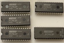
For Sale BB PCM63
I have a total of nine PCM63. Please refer to pictures.
Sold separately or as a lot. Open to offers.
Ships from Sweden.
Regards
R
Sold separately or as a lot. Open to offers.
Ships from Sweden.
Regards
R
Attachments
Change (downgrade) of media-HTPC machine
I have a (silent) PC in the living room, which ran numerous virtual machines including a music/media one. However, there were some complications with that idea, so ultimately the whole PC became dedicated just to browsing the internet and streaming/playing music & movies on the TV. Even running the crossovers, DSP & EQ became farmed out to a raspberry Pi in USB 'gadget' mode. The big PC is therefore a bit unnecessarily large and under-utillised for this, so I intend to pass it onto a relative with more needs than myself, and build a more modest little media/HTPC machine for myself.
I know there are lots of tiny fanless machines that would suffice, but I'm reluctant to downgrade 'too' far or lose too much flexibility/connectivity (external ports, RAM and nvme SSDs etc). Partly because I want years of future-proofing and partly because I don't need to achieve the 'absolute' minimum in power or size. It won't be left on 24-7 and something like a 2u rack-mount case would fit quite nicely with my amps. It really just needs to be modest 'enough' to cool passively without fans or tall internal heatsinks (and I don't want the complication of water cooling etc). So, maybe a 'T' flavour of an intel CPU (though they seem less readily available to consumers) or a standard i3 CPU might be the sweet spot. The latter are around 60W TDP but rising to only 90-110W even on turbo. I vaguely recall it is possible to cap the turbo on some higher-end CPUs too, though whether that is wasteful over getting a lower-end one to begin with I don't know.
My thoughts (so far) are for a modest but normal desktop processor in a case with sides (and/or front) that comprise heatsink(s). Such passive HTPC cases are available - at huge price - and suggest that handling a CPU up to ~95W is a reasonable aspiration. But I already have several large Conrad heatsinks, of the type sometimes seen forming the walls of class-A or AB amps. Also, heat-pipes are available for the DIYer, which could be used to thermally bridge the CPU to the case's wall, so I think/hope that a DIY solution may be possible for modest money.
Though I'm probably reinventing the wheel here, so if anyone has been there or got useful suggestions I would of course be interested to hear!
Kev
ADAM Active Studio Monitor schematic diagrams help
Gentlemen,
in my workshop I have these active S1A "Professional Studio Monitor"
loudspeakers for repair. The amplifier is defective. Resolved, this is an
ADAM schematic collection now.
A diagram of this module would be useful. It is made by Hypex of the
Netherlands, no designation on it but date 10 Jul 2003. It carries a vast
number of NE5332 ops and two TDA7294 power amps, one LM339 and
one TL074 are also visible. Should be manageable to repair, but all traces
and joints are very small - doesn't help my eyes.
The Adam company which is in Berlin says that they don't have any
documentation and can not repair it. Since many of these were sold
it would be good to have them fixed in the true sense of sustainability.
I suspect that other people have problems with the amps also.
I understand that the head of R&D of Hypex is also around in this forum.
Will he be willing to assist?
Any help is highly appreciated, thanks.
EDIT: Diagram for S1A is in post 10.
Diagram for ADAM P33 (UCD-Version) is in post 152.
Schematic for ADAM P7 is in post 12,
Service manual for ADAM P 11 A UCD see post 154,
same for P11A analog in post 205
P22a manuals are in post 155
S2A ICE schematics in post 218
S2X documents are in post 258
ADAM S2.5A and S3A schematics added in post 89 and 90
Model S1A (and others) transformer mounting precaution in post 19.
Model F7 is in post 149
ADAM S3XH Service Manual is in post 153.
ADAM S3XV Service Manual is in post 170.
ADAM S4XH papers are in post 232.
ARTIST 6 documents in post 208.
Measurements and correction filters for a few Fostex enclosures
- By talaerts
- Full Range
- 13 Replies
I found links to a few magazine articles in German testing the well known classic Fostex enclosures, and usefully also recommended filters to flatten the frequency response. These filters could be of interest as well in other enclosure designs as they work higher up in the frequencies.
This is linked from the site of a German dealer of horn speakers and kits, often using Fostex drivers.
It is interesting to see how the drivers and well known enclosures perform. These were articles from the magazine Hobby-Hifi which I like to buy whenever I am back in Europe.
Hence:
If I would build one of these enclosures I would use 3 terminal plugs so I can connect before and after the correction filter to experiment.
This is linked from the site of a German dealer of horn speakers and kits, often using Fostex drivers.
It is interesting to see how the drivers and well known enclosures perform. These were articles from the magazine Hobby-Hifi which I like to buy whenever I am back in Europe.
Hence:
- The elegant small FE103 horn. I was always curious about it. They say, as the measurement shows, that the bass is not impressive when measured properly in free air, but it is a lot more full sounding against a wall (as expected). Also useful is their recommended correction filter on page 4 (effect is shown in the frequency plot), plus an optional impedance correction when used with a tube amp:
https://eckhorn.com/bk-103.html?file=files/jpx/content/download/bk103.83.pdf - The BK108 horn for FE108EZ. Correction filter on p9:
https://eckhorn.com/bk-108.html?file=files/jpx/content/download/TESTBERICHT-BK108.pdf - The old enclosure for the FE206En. Unfortunately the shop’s filter is not published; however there is an interesting addendum measuring the FE206En in the FE208EZ enclosure. It has better bass in it and thus this enclosure is recommended instead, unless if you have a small room.
https://eckhorn.com/bk-206.html?file=files/jpx/content/download/bk206.82.pdf - FE208EZ in its enclosure with T900A super tweeter. The magazine publishes its filter next to the shop’s filter, the response looks better with the magazine’s filter.
https://eckhorn.com/bk208-mk-ii.html?file=files/jpx/content/download/BK208.pdf - FE166 horn with the FE168EZ or the rare limited FE163En-S and T90A tweeter. Filter including correction added on p9. Recommended to put this box against a wall.
https://eckhorn.com/bk166.html?file=files/jpx/content/download/BK166.pdf - BK83SOL enclosure also tested with FE83En and FF83WK. Correction filter on p10 is said to work well with any of the 3 drivers.
https://eckhorn.com/bk83sol.html?file=files/jpx/content/download/BK83Sol.pdf - BK12M with FE126En or now rare FE108-SOL (they really like this last driver). Correction filters on p8 (FE126En) and p9 (FE108-SOL). Best to put against a wall. They also compare with small FE103 horn and BK108 for FE108EZ. FE108SOL is the best sounding according to the magazine, and would be even better in the BK108 enclosure - more bass.
https://eckhorn.com/bk-12-m.html?file=files/jpx/content/download/BK-12m.pdf
If I would build one of these enclosures I would use 3 terminal plugs so I can connect before and after the correction filter to experiment.
SXA 100 I'm looking for a diagram
- By AndrésArg
- Solid State
- 5 Replies
Hello everyone.
I'm looking for a reference schematic to better understand this amplifier.
The problem is that there's no volume control (it's set to high) and it's very noisy.
It would be something like this:
I'm looking for a reference schematic to better understand this amplifier.
The problem is that there's no volume control (it's set to high) and it's very noisy.
It would be something like this:
Attachments
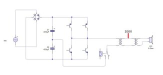
6C33C SET Monoblock
- By dubadub
- Tubes / Valves
- 29 Replies
Greetings Friends. I've been fascinated by the 6C33C since I first laid eyes on it, and I've been kicking around an idea for a simple SET amp featuring the triple nipple. Borrowing the driver (and schematics) from the 6336 SET Amp by @Suncalc this amp uses cathode bias and the high voltage swing driver to make ~15 watts of Class A power.

Edcor's CXSE25-600 is a 25-watt OPT with a 600 ohm Primary and 8 ohm Secondary. According to my dummy math, 360v to the OPT will give a Va-k of 250v and a Vk of 88v, with a 400 ohm Kr.
Eliminated the volume control from the input, replaced with a 250k resistor.
Grid Leak Resistor for the output stage changed to 200k. Grid Stopper necessary?
Not sure how to calculate the K bypass cap.

Surprisingly the Hammond 372JX provides all the power needed. The output stage's cathode resistor eats so much b+ that there's no problem getting the 300v for the driver stage.
Enough capacitance for such a large current draw?
Better to take the driver stage power from before or after the 2nd choke?
Thoughts?
thanks for taking a look!
w
Edcor's CXSE25-600 is a 25-watt OPT with a 600 ohm Primary and 8 ohm Secondary. According to my dummy math, 360v to the OPT will give a Va-k of 250v and a Vk of 88v, with a 400 ohm Kr.
Eliminated the volume control from the input, replaced with a 250k resistor.
Grid Leak Resistor for the output stage changed to 200k. Grid Stopper necessary?
Not sure how to calculate the K bypass cap.
Surprisingly the Hammond 372JX provides all the power needed. The output stage's cathode resistor eats so much b+ that there's no problem getting the 300v for the driver stage.
Enough capacitance for such a large current draw?
Better to take the driver stage power from before or after the 2nd choke?
Thoughts?
thanks for taking a look!
w
Is any of these 2 xover technically preferable?
I have diy a 2,5 way 9 drivers linesource with pointsourse "function/treat"
And I have now listened to a few different filters for 1-2 months, & have started to minimize the number of components as I felt that neither a notch filter nor even using HP added anything in terms of sound.
Real happy with the sound even if maby some small tweaks is left on the xover, but use 2 different xover today for left and right speaker.
I want to finish them and mount the "finish xover" on a plate inside the speaker, so the speakers is "completely finished" to be connected from my amp.
I have a bad habbit to not finish my diy´s xover, and have loose hanging xover on the floor and parts everywhere.
And sometimes my kids ran into them, so i have to almost "start over"
So this time I WILL "finish them"!
Is any of these 6 parts xover "better" purely technical, phase wise, impedance etc ?
The wiggle at 1300 hz dont exist in my measurements from 2 meters or further away, and i sitt about 3,2-3,5 meters from the speakers.
Today crossed around 3K to the WG tweeter
best regards John
Attachments
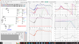
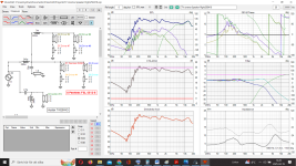
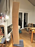
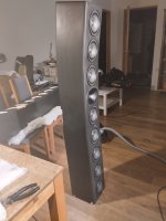
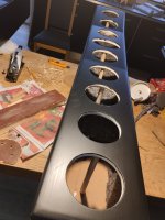
Foster (Fostex) LC300 Crossover Schematic
- By irivlin
- Introductions
- 22 Replies
Does anyone have a schematic for the Foster (also called Fostex) LC300 3 way crossover? I have a pair of Goodman's speakers with the Foster crossover. I want to rewire the speaker and don't know which connections go where.
Thank you
Ian
Thank you
Ian
Realistic Optimus 1B
Was donated a pair of these today, Crossover attached
The woofer (2519Aa Japan) looked promising with a low Fs & Qt, parameters:
Fs 20.75; Re 7; Qe .38; Qm 5.53; Qt .35; Vas 142.38; Sd 314; Le .84; eff 87.6
did some sims, Woofer looks good in 60L (Optimus oix is 38L), tuned to 22Hz
all this fun & I haven't listened to them yet....
The Big Q: Do I restore them to original, or 'improve' them to my own taste....???????
Bugger, just realised I left the tweeter switch out of the xover diagram, give me a few minuets....
Attachments
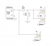
Fanless miniPC
- By jan.didden
- Equipment & Tools
- 64 Replies
I'm looking for a small, fanless miniPC to run my JRiver server and Tidal. W10.
I have a small HP laptop and an even smaller AERO FARA but both have a fan that is disturbing at serious listening.
Also would like an USB-C/Thunderbolt connection for the display.
And a bunch of USB ports of course.
Any tips?
Jan
I have a small HP laptop and an even smaller AERO FARA but both have a fan that is disturbing at serious listening.
Also would like an USB-C/Thunderbolt connection for the display.
And a bunch of USB ports of course.
Any tips?
Jan
-
Locked
Aliexpress Chinese ES9039Q2M module... what can we do with it?
- By jean-paul
- Digital Line Level
- 10 Replies
https://de.aliexpress.com/item/1005...MIrJrh_sL7jAMVkJ9oCR1oBBgQEAQYASABEgKwA_D_BwE
As the thread title. Could this be the new kid on the block that is both cheap and good enough (or better) performer? Is this model usable in a poroject and what can we do to solve possible shortcomings or is it OK as it is? Mine is on its way and I am curious. Are you too?
As the thread title. Could this be the new kid on the block that is both cheap and good enough (or better) performer? Is this model usable in a poroject and what can we do to solve possible shortcomings or is it OK as it is? Mine is on its way and I am curious. Are you too?
Marantz PM-66SE KI Signature PSU Modifications
- By Hamish119
- Solid State
- 23 Replies
I recently purchased a Marantz PM-66SE KI Signature (the same circuit as the PM-40SE, PM-44SE and PM-66SE, but with a toroidal transformer, a sprinkling of 'boutique' capacitors and a copper-plated chassis.
N.B. The PM-66* variants have an extra transformer winding for the remote control features.
Whilst it appeared to be fully-functional (** I normally listen with the 'Source DIRECT' button engaged **), I was concerned by the amount of heat dissipated by Q801 & Q802.
I resolved to reduce the amount of heat dissipated by these transistors with the minimum amount of circuit modifications and parts.
I noted that R802 had been replaced. I also noted that Q801 was loose! Too much heat in a TO220 package.
Marantz_PM-66SE_KI_1_small.mp4
Marantz_PM-66SE_KI_2.mp4
N.B. I had a Marantz PM-44SE that used to intermittently drop-out the speaker relay, then re-engage a few seconds later. That amplifier 'disappeared' before I could investigate the cause (I now suspect Q801 as aove).
After measuring the voltage drops across R802 (47R / ~5V drop) and R804 (47R / ~3V drop), I determined that the +24V rail was supplying ~100mA (worst case - speaker + source direct relays engaged) and the -18V rails was supplying ~66mA (worst case - ALL LEDs illuminated).
It's not surprising that (according to 'the Internet') R802 is the most common failure with these amplifiers - it's severely underrated. It's a design oversight!.
R804, D804 & D805 also take a beating in the default configuration.
Marantz_PM-66SE_KI_PSU.jpg
Marantz_PM-66SE_KI_Resistor.jpg
** When I disengaged the 'Source Direct' relay, I lost the right channel (intermittently). Re-engaging the 'Source Direct' relay restored the right channel (always).
After replacing ALL the semiconductors and capacitors, the amplifier was completely destroyed. 😱
The above sentence is completely untrue and is precisely what happens when you believe 'misinformation' on the Internet. 🙄
The right channel could be restored (temporarily) by moving the large ribbon cable (WV01), but would disappear minutes/hours later.
After chasing the intermittent problem, I discovered that the (never used) 'Balance' control had been 'whacked' by a previous (l)User.
Resoldering ALL the pins restored normal operation (but for how long?).
Balance_Control_Knob.jpg
Attachments
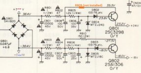
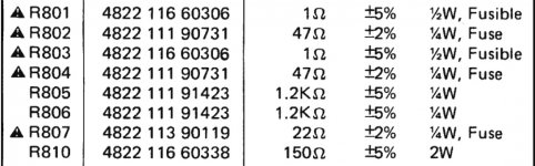

Ohm F: source for 4-ohm voice coil (or better) ???
- By artm
- Planars & Exotics
- 0 Replies
Does anyone know a source for Ohm F 4-ohm voice coils (original spec)? All I'm able to find is a replacement 8-ohm version.
Alternatively, any "better" options to consider?
Alternatively, any "better" options to consider?
For Sale 8" Ultimax in sealed MDF cabinet
This is a built kit from PE. $145 shipped CONUS. It's heavy for its size so shipping will probably not be cheap. If anyone local wants it we can talk a cheaper price
Attachments
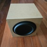
I'm Pete from Cleveland
- By PeteyWheaty
- Introductions
- 1 Replies
Hi all. I've been bitten by the repair/restore bug. I'm currently waiting for a relay to (hopefully) complete a Sony TA-S9000es repair, and then moving on to a Sony TA-N9000es. Thanks in advance for all of your support.
Other victims:
Sansui 2000
Olson RA-194
Other victims:
Sansui 2000
Olson RA-194
need a schematic for Sonographe SC25 preamp
- By moray james
- Solid State
- 5 Replies
a url or a copy of the schematic would be a big help. Thanks.
PA amp from Ali...
- By KaffiMann
- PA Systems
- 59 Replies
Just ordered the PFA10K from ShennDare, a very new design it seems.
REEEEEAAAALLY hoping it's useable, feeling a bit apprehensive.
If all else fails I hope it is possible to delegate it to subs only...
Edit:
Link
REEEEEAAAALLY hoping it's useable, feeling a bit apprehensive.
If all else fails I hope it is possible to delegate it to subs only...
Edit:
Link
Hi, I'm Martin
- By MartinJaeger
- Introductions
- 1 Replies
Dear all,
My name is Martin and I live in Germany.
For a couple of years now, I've been collecting and trying to repair vintage audio gear (mainly SONY receivers, amps, and turntables from the 70s and 80s), but I still consider myself a beginner.
I hope that one day I can also share my knowledge with the diyAudio community.
Best,
Martin
150W MOSFET Amplifier with IRFP250x2
- By apexaudio
- Solid State
- 488 Replies
This circuit is upgrade on BUZAMP from Elektor. Use only N-mosfets, with +/-50V DC give 150W on 4R load.
Attachments
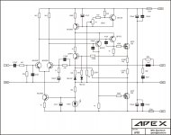
For Sale Acro Acrosound TO-330 Output Transformer
Sold, Thanks for interest!
Acro T0-330 Output Transformer.
Primary: 3800 ohms, screen taps for Ultra Linear operation, Parallel PP 6550s, EL34s
Secondary: 4, 8, 16 ohms
I verified turns ratio & Z ratio using 10V rms 1Khz on the secondary and reading the primary voltage.
$200 plus shipping. US lower 48 only


Acro T0-330 Output Transformer.
Primary: 3800 ohms, screen taps for Ultra Linear operation, Parallel PP 6550s, EL34s
Secondary: 4, 8, 16 ohms
I verified turns ratio & Z ratio using 10V rms 1Khz on the secondary and reading the primary voltage.
$200 plus shipping. US lower 48 only
For Sale Clearance of spot inventory, transistors, vFET, TOKIN THF-51N THF51N TO-79 gold-capped tubes, old used Passed the test
Update the latest spot, you can circle the VGS you want, and friends who want more quantity can negotiate the price.
1: Only 1 piece of old 2SK180 USD: 50
2: Only 1 piece of old 2SK181 USD: 50
3: Old THF-51N THF51N THF51N and THF-51S functions the same. Friends in need, please see the picture below. It is cheap For sale, tested, please browse if there are data records, and there is an exact match. 1 piece USD: 50 China Post USD: 12-20
For Sale (from Switzerland): Sony VFET N-Channel built + fully functional
The Gem is sold.
I have too many things, and am willing to let go my Sony VFet amp I was able to get from the lottery...
I strictly followed the build guide, and nothing was added or upgraded.
I'm asking CHF 700.– plus shipping which would be from switzerland, so europeans have a little advantage, and fellow swiss folks may even pick it up...
Fotos may follow as soon as I'm in my atelier again...
Attachments
-
 IMG_7792.jpeg674.2 KB · Views: 221
 -
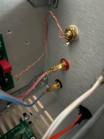 IMG_7791.jpeg721.4 KB · Views: 199
 -
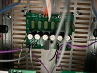 IMG_7790.jpeg825.1 KB · Views: 215
 -
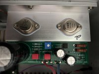 IMG_7789.jpeg745.1 KB · Views: 212
 -
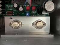 IMG_7788.jpeg646.8 KB · Views: 218
 -
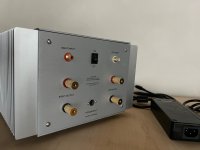 IMG_7787.jpeg598.5 KB · Views: 205
 -
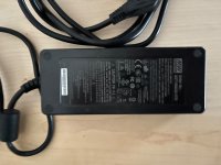 IMG_7786.jpeg870.1 KB · Views: 216
 -
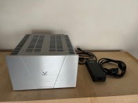 IMG_7785.jpeg646.5 KB · Views: 217
 -
 Bild 6.jpeg141.5 KB · Views: 222
Infill percentage experiment for 3D printed speaker cabinets
Login to view embedded media
I don't see that this has been posted anywhere so sorry if this is a repeat post
I don't see that this has been posted anywhere so sorry if this is a repeat post
LND150 Gain Stage hum
- By john65b
- Instruments and Amps
- 11 Replies
Hey all, I have this nice Magnavox 138BB tube amp that I use as a Guitar amp (stock) and driven with a Joyo American Sound pedal/preamp. Works ok, but not very loud...so I added a LND150 Gain stage in front of it. Now plenty loud but has quite a bit of hum...sounds like 60hz... I like this setup....pushes the 6V6 nicely.
The 220 ohm source resistor leaves me with around 125vdc at drain (1/2 B+), so I think the LND150 is biased correctly....but would like to reduce the hum... any advice? Thought of reducing the R2 from 1M to 470k....
I am "stealing" B+ from the two high side of the 470k anode resistors in maggie amp.
Without the LND150 circuit, no hum at all...
Attachments

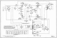
For Sale Matched pair of NOS BBC LS 3/5 woofers
Graham Audio version, dealer's stock, quite impossible to source -$350. Pictures for interested parties if any.
It is meant for this
https://almaaudio.com/products/grah...-ghbZyoPnjA2RO7KLMDdcw1zsZDnn25hoCrbAQAvD_BwE
But I'm pretty sure it will work in any LS3/5 project because it is called a true BBC version
It is meant for this
https://almaaudio.com/products/grah...-ghbZyoPnjA2RO7KLMDdcw1zsZDnn25hoCrbAQAvD_BwE
But I'm pretty sure it will work in any LS3/5 project because it is called a true BBC version
I've killed my Sony TA-F770ES by starting a recap (yes, I know) and I would dearly love some help
- By Howard
- Solid State
- 73 Replies
Hi everyone,
To put it bluntly, my lovely Sony TA-F770ES amp was working perfectly fine until I, after much deliberation and research, decided to re-cap it on account of its age.
It now doesn't work, I regret absolutely everything, and I would like some help if at all possible!
I started off with just the Main (A) board - the smaller preamp/driver board, and the phono stage board. They're the smaller boards stacked up on the right.
After doing both, no issues, I put them back in to test it before moving on.
It powered up, the lights lit up, the power light went green, then a couple of seconds later it went into protection.
"Bugger", I said. OK, maybe I mis-connected something or something is shorting that shouldn't be. I took it all back apart and meticulously checked and reassembled everything.
Same issue.
A while ago I bought an 870ES donor amp which was not working and in a poor cosmetic state - I wanted to harvest it for the unobtanium parts such as ICs/switches/pots.
So I swapped in the donor amp's amp and EQ boards (they are identical apart from a couple of slightly more highly-specced values here and there to account for the extra power of the amp).
Same issue.
Now, my memory is hazy of exactly how long I spent fiddling and checking all my connections and making sure nothing was visually wrong, but somewhere along the line, the front panel and volume LEDs stopped working.
I learned from this thread https://www.diyaudio.com/community/threads/sony-ta-f770es-tone-control-oscillating.351940/ and somewhere else that the volume knob LED and all the other LEDs are in series and for some reason are crucial to the front panel circuit working properly.
So I double-checked everything, all the connections, all the ground points, I even swapped in the donor (again, identical) front panel control logic board but again the same issue.
I really want to try and troubleshoot this but I'm not entirely sure where to go from here. It seems like it might be something to do with the front panel LEDs/connections but I'm not adept enough at reading circuit diagrams to fully comprehend it.
It can't be completely dead because:
1. The LEDs on the Main (A) board light up - one green one orange
2. The heatsink gets warm so the main transistors are doing their thing
3. Despite the LEDs not working, the buttons on the front still operate the motorised rotary input switch
4. The remote control still works and operates the volume
But there's no attempt to trigger the protection circuit anymore.
Thanks so much in advance for any insight.
Fosgate PR-2100 help
So I have been playing with some "old school amps" or so I thought. A older friend of mine tells me of a Fosgate amp he has stored and ends up bringing it to me. Holly crud! I don't know old school since it sure is not around the late 80-90 range, it's the mid to late 70's!
Anyway, I took covers off and took pics and measured power and ground leads and seem plausible. The speaker outputs all measure about 42ohm and that waved a flag to me. Sounds way too low. I studied up on how to power the amp up using a current draw on the red lead and it is cycling on/off about 2 cycles second. This is just like my friend told me it was doing when he tried it on a power supply years ago. He said it would play but only would stay going if kinda loud and would cycle if played at low volume, from what I recall from speaking to him. I was in shock after all. I did not hook up to a speaker or take any voltage measurements on the speaker leads yet as I am a little nervous with this rare amp. I thought it best to just go straight for some advise.
I tried powering with both a car battery and power supply combined and same result as just my 30amp power supply.
The F6 Revisited
- Pass Labs
- 633 Replies
A little over a month ago I mentioned wanting to start a new PCB for the F6 that included some common and not-as-common tweaks that have found there way into the diyAudio community. This idea received positive comments and launched two new PCB designs.
https://www.diyaudio.com/community/threads/zenductor.402522/post-7469793
Mikerodrig27 created the PCB artwork for two new variants, one with the standard JFet input stage and one with the Diamond buffer. I have had the PCBs for a few weeks already. It took some extra time to rebuild an old test bed to avoid a prominent 120 Hz hum. Plus I was away on vacay for over a week. All better now.
Cutting to the chase – The performance of the new JFet PCBs has exceeded my expectations. Soldering the green LEDs into the PCB has enhanced the function of their negative temperature coefficient (NTC). There is a more pronounced boost to initial bias current while the amp is cool, then the current drops as the amp heats up. The net effect is that the amp is effectively temperature stable after a half hour, and bias current does not drift appreciably after that.
The new PCBs are built around the Jensen JT-123-FLPCH signal transformers, as standard. We could entertain a dual footprint that included the Cinemag CMOQ series, but my listening experience so far has been wonderful with the Jensens. I don't have any info yet on the lower cost signal transformer proposed for the new F6m variant. I think we may leave that for the diyAudio store.
I chose to build the JFet input version first, with IRFP048 Mosfets. This turns out to be a great combination. I can highly recommend the IRFP048 for future builds by DIY enthusiasts. The store carried these for a while, and they are inexpensive and readily available from Mouser and Digikey.
I am making further mods to the power supply of my test bed and will post more on that and the listening tests soon.
Attachments
For Sale Several tube power amps for sale
I realized that I have two ears, 4 speakers, and about 16 tube amps. So I want to get rid of some. I have them listed on eBay, but am happy to kill the listing(s) and sell them directly if anybody is interested.
More info on my website pmillett.com or you can see the listings on eBay:
https://www.ebay.com/itm/1674531214...M6XS4H&hash=item26fcfbdb83:g:xkoAAOSwtTVn~U7X
https://www.ebay.com/itm/1674532051...PK9TB0&hash=item26fcfd228c:g:c40AAOSwzxRn~V7T
https://www.ebay.com/itm/1568922170...BEWVJ2&hash=item2487813ee9:g:bMEAAOSwHN1n~UhC
Pete
Attachments
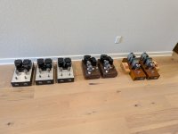
FET's transfer curve analyser aka locky_z to handy numbers
- By ripson
- Software Tools
- 0 Replies
For my needs I created this little PowerShell tool and I wanted to share it. It is made to help picking FETs based on their transfer curves.

Instead of just looking at the curves, it can calculate some basic numbers like how linear the device is across the range.
It’s mainly for people who want to select FETs by linearity, transconductance, and want an easier way to spot which FETs behave nicely, meaning more consistent gm and fewer surprises.
What it does:
PS. How to run it? Unpack it and in Windows just right click and "Run with PowerShell", for security reason please ALWAYS check the script or any other modified for any suspicious code, it is a text based file.

Instead of just looking at the curves, it can calculate some basic numbers like how linear the device is across the range.
It’s mainly for people who want to select FETs by linearity, transconductance, and want an easier way to spot which FETs behave nicely, meaning more consistent gm and fewer surprises.
What it does:
- Reads your transfer curve data (like from a Locky_Z tracer)
- Calculates transconductance (gm) at different points or average within the curve
- Gives a quick idea of how "linear" the FET really is (from 0 to 1 where 1 is a straight line)
- Makes it easier to pick better parts without having to guess from the graphs
PS. How to run it? Unpack it and in Windows just right click and "Run with PowerShell", for security reason please ALWAYS check the script or any other modified for any suspicious code, it is a text based file.
Attachments
Yamaha M-4
- By miguelnoda
- Solid State
- 2 Replies
Hola tengo una etapa Yamaha M-4 y tiene varias resistencias fusibles que mal se podrían sustituir o se pueden conseguir
Pass F4 Investigations
I will just do SPICE simulations. Will be no building 🙂
Pass F4 is an intriguing amplifier. Can be called a high current power buffer.
To begin with I will be focusing on the original F4 as can be seen in service manual.
I know there are some modified versions, but they have their own life.
The original version can be seen in my image.
I have stripped off the JFET input stage, because most preamplifiers have no problem with F4 input impedance.
Some facts I have found out:
Gain: 0.97
Input impedance: ~8 kOhm
Distortion THD:
01 W: 0.003%
02 W: 0.004%
04 W: 0.007%
10 W: 0.013%
20 W: 0.028%
Technics SE-A3 bias adjustment
- By uchu007
- Solid State
- 100 Replies
Good morning, I have just finished reassembling my Technics se-a3 and I am wondering about the adjustment of the quiescent current in the doc it indicates to adjust the potentiometer vr104 and vr105 to minimum but it does not indicate the direction and what is the minimum resistance level or the opposite? Sincerely
Attachments
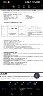
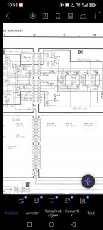
Rod Elliot ESP P09 active crossover optimal R and C values
- By amplidude
- Analog Line Level
- 15 Replies
Hi all,
I'm working on a 3-way active Linkwitz-Riley crossover (24dB/oct), based on the ESP P09 topology. The setup is for home hi-fi use at moderate listening levels — I rarely play loud, and my focus is on sound quality, transparency, and phase coherence.
My speaker system consists of:
Tweeter: Electro-Voice ST350B
Midrange: Electro-Voice EVM-10M in a sealed 18L chamber
Woofer: JBL 4227 in a 130L bass reflex cabinet
The crossover is built on a KMTech board. I’m using LME49720HA opamps with proper bypassing and layout attention. I also have a large stock of mil-spec 10k resistors with tight tolerance, and a selection of precision film capacitors including rare KS and military polypropylene types.
What I’d like your input on:
1. Suggestions for optimal crossover point placement for these specific drivers, considering phase alignment and natural acoustic blending.
2. Thoughts on using LME49720HA opamps in this type of filter — are there any caveats or fine points I should be aware of?
3. In general, what’s your preferred strategy for selecting component values: fixing R and calculating C, or the reverse? Any experience-based sweet spots in terms of impedance?
4. Any practical tips from your own active crossover builds with similar gear?
Thanks in advance for sharing your experience — much appreciated!
Half decent small mixer with MIDI I/O
- By KaffiMann
- PA Systems
- 71 Replies
The results from the thread:
Audient id48 will be used as the main interface.
DAW mastering will mainly be handled using touchscreen.
MIDI is better handled by stand alone solutions, will most likely get something like the CME U6 MIDI Pro which is a USB interface with 3 x I/O, and having a single dedicated multiple I/O MIDI unit can help reduce issues with sync.
Here is the original 1st post:
Hello people,
Looking for a half decent small mixer with at least:
4 Mic/instrument inputs
1 stereo input
USB for using as an audio interface
MIDI I/O for use with synths
Good noise figures
Not too expensive
I do not have a huge amount of experience looking for mixers so I was hoping for some advice, basically I want 1 thing that do all these things instead of having lots of boxes with lots of signal routing in between.
So far it seems the Tascam Model 12 may be my best option, but with my limited knowledge in this particular field there might be some other good contenders that I have no idea about.
Been looking at devices with compareable specs like the Yamaha MG12 XU but it has no MIDI, and the Tascam does look much better even though that is not a requirement of mine it is sort of a bonus to have the aesthetics covered.
Thankful for any advice not involving a cluttered mess of 3 different items to fulfill these criteria.
For Sale RJM Emerald phono preamplifier
For sale: RJM Emerald phono preamplifier.
The preamp was barely used because I sold the turntable shortly after building it.
It has been tested and is working. During testing, there was a bit of excess noise, but I’m not sure whether the issue was with the preamp or the turntable.
It’s being sold as-is, as I simply don’t have the time to investigate further.
Built with high-quality components:
Aluminum enclosure, AC filter, audio-grade 80VA transformer, additional Nichicon MUSE capacitors in the power supply, Jantzen Superior Z-cap, Wima, Dale resistors, Elna Silmic II, Mundorf Silver-Gold solder...
Price: 300€
Attachments
-
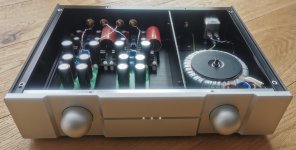 IMG_20250410_085726_Y.jpg239 KB · Views: 97
 -
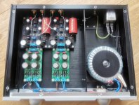 IMG_20250410_085733_Y.jpg431.4 KB · Views: 100
 -
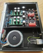 IMG_20250410_085743_Y.jpg444.1 KB · Views: 92
 -
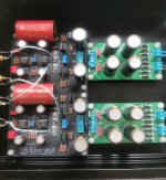 IMG_20250410_085753_Y.jpg474.9 KB · Views: 90
 -
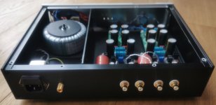 IMG_20250410_085800_Y.jpg163.8 KB · Views: 81
 -
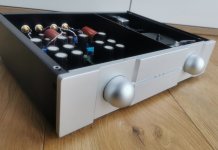 IMG_20250410_085827_Y.jpg251.2 KB · Views: 88
 -
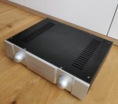 IMG_20250410_085921_Y.jpg345.5 KB · Views: 89
ADAU1452+AD1938 DSP crossover
- By bogdan2011
- Digital Line Level
- 13 Replies
Hello,
I'm building an ADAU1452 based DSP crossover with the AD1938 codec. The features I need are:
It's largely based on the datasheet and EVM. Though I want to keep it simple and compact, so no ADC or GPIO stuff, no digital output etc.
What I am unsure about is how to program the thing. There's not much info on this apart from using the official USBi programmer, but I read that a FX2LP programmer should work? Also I don't want to use a 1Mb eeprom, is 256k enough for a simple program?
Anyway, here is the schematic:
I'm building an ADAU1452 based DSP crossover with the AD1938 codec. The features I need are:
- SPDIF input
- 2 ch (stereo) analog input
- extra I2S input
- 3 outputs per channel, so 6 outputs in total
It's largely based on the datasheet and EVM. Though I want to keep it simple and compact, so no ADC or GPIO stuff, no digital output etc.
What I am unsure about is how to program the thing. There's not much info on this apart from using the official USBi programmer, but I read that a FX2LP programmer should work? Also I don't want to use a 1Mb eeprom, is 256k enough for a simple program?
Anyway, here is the schematic:
Attachments
-
Locked
What are the Capacitors ??
- By thebear13
- Analog Line Level
- 1 Replies
Hi - noobie post. I was looking to upgrade these old capacitors in my tube pre-amp. I am not sure what the these values are - one of them says ' 100M + 100M , and the other 2 say ' 32M + 32M ' - any ideas , guys ???

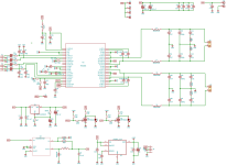
For Sale PSU board for DAC
As on the picture. 6 independent lines, PCB + Diodes + terminals = 10 EUR + shipping.
For free if you buy York: https://www.diyaudio.com/community/...tichannel-input-output-interface-york.413504/
For free if you buy York: https://www.diyaudio.com/community/...tichannel-input-output-interface-york.413504/
Attachments
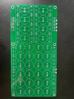
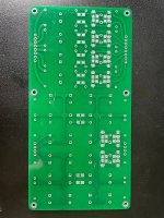
Akai CD-93
- By tuncay
- Digital Source
- 246 Replies
My AKAI CD 93 cd player needs an M50747-433SP. This is an ic produced by Mitsubishi for Akai CD93 and CD73 model cd players.
Load more
Projects by fanatics, for fanatics
Get answers and advice for everyone wanting to learn the art of audio.
Join the Community
508,473
Members
7,921,240
Messages