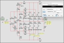
I will just do SPICE simulations. Will be no building 🙂
Pass F4 is an intriguing amplifier. Can be called a high current power buffer.
To begin with I will be focusing on the original F4 as can be seen in service manual.
I know there are some modified versions, but they have their own life.
The original version can be seen in my image.
I have stripped off the JFET input stage, because most preamplifiers have no problem with F4 input impedance.
Some facts I have found out:
Gain: 0.97
Input impedance: ~8 kOhm
Distortion THD:
01 W: 0.003%
02 W: 0.004%
04 W: 0.007%
10 W: 0.013%
20 W: 0.028%

Last edited:
Interesting - in my simulation the bootstrap does not - as usual - add some headroom in the form here without feedback, of a higher output. For example 19.6Vpp against 19.7Vpp. But for sure it makes the life of the input pair easier. The Vds becomes more constant, specifically with such large swings as 20Vpp in. The F4 has a very low 'insertion loss'!
