Hello,
I'm building an ADAU1452 based DSP crossover with the AD1938 codec. The features I need are:
It's largely based on the datasheet and EVM. Though I want to keep it simple and compact, so no ADC or GPIO stuff, no digital output etc.
What I am unsure about is how to program the thing. There's not much info on this apart from using the official USBi programmer, but I read that a FX2LP programmer should work? Also I don't want to use a 1Mb eeprom, is 256k enough for a simple program?
Anyway, here is the schematic:
I'm building an ADAU1452 based DSP crossover with the AD1938 codec. The features I need are:
- SPDIF input
- 2 ch (stereo) analog input
- extra I2S input
- 3 outputs per channel, so 6 outputs in total
It's largely based on the datasheet and EVM. Though I want to keep it simple and compact, so no ADC or GPIO stuff, no digital output etc.
What I am unsure about is how to program the thing. There's not much info on this apart from using the official USBi programmer, but I read that a FX2LP programmer should work? Also I don't want to use a 1Mb eeprom, is 256k enough for a simple program?
Anyway, here is the schematic:
Attachments
It will be if you configure it as USBi.but I read that a FX2LP programmer should work?
Use W25Q80DV they are cheap and available.Also I don't want to use a 1Mb eeprom, is 256k enough for a simple program?

Like this?It will be if you configure it as USBi.
https://oscarmcnulty.com/2020/07/09/programming-adau1701.html
How about using York nano?What I am unsure about is how to program the thing. There's not much info on this apart from using the official USBi programmer
It would allow to program the DSP from SigmaStudio and stream (multichannel) audio at the same time, using one USB:
Hello DiyAudio community,
TL;DR: This is a USB transport for audio output (up to 8ch) and input (2ch for now) and user device control (e.g., DSP management) from PC (MacOS/Linux/Windows) thru I2C/GPIO. Including bootloader for remote firmware update, flexible device configuration, HID interface, multiple audio output options, integration with SigmaStudio (simultanious audio playback and ADAU DSP configuration). Compact module available in USB-C and USB-B versions, isolated or non-isolated.
Latest docs, config tool, link to buy:
http://york.eclipsevl.org/...
Interesting project, I hope you can integrate the York and a wifi streamer like Arylic or maybe something better (App controlled - non BT) and make it into a group buy once completed . All the best !
I actually managed to flash an FX2LP with the USBi firmware and hopefully I can use that to program the chip. I'll check out the York as well.
For the source I have an Arylic BP50 and I'll connect it to the crossover via SPDIF, but there's an I2S port on the board so I can theoretically plug in any I2S source.
In this regard, I'm unsure how input mixing works, can I just add a mixer component or do I need to do some kind of input switching via software?
Attachments

Hi, I am not sure how the input switching will be done - however a question is will it be required ,
On one hand the people that will use Arylic will be choosing the App control ease of making their speakers wireless and other functionalities that come in the wifi / app environment - than - hardwiring source to the DSP.
On the other hand the purists will most probably skip streaming and prefer hardwiring source & speakers.
Therefore inclusivity of Arylic can be kept as an option, as once the dsp has been setup by the user gaining access to the dsp and input switching will require you to add another pcb like and remote like uriy has done here
where if one uses Arylic everything is controlled through the App.
On one hand the people that will use Arylic will be choosing the App control ease of making their speakers wireless and other functionalities that come in the wifi / app environment - than - hardwiring source to the DSP.
On the other hand the purists will most probably skip streaming and prefer hardwiring source & speakers.
Therefore inclusivity of Arylic can be kept as an option, as once the dsp has been setup by the user gaining access to the dsp and input switching will require you to add another pcb like and remote like uriy has done here
I'm new to this, so please be prepared for some strange questions...
a) Installed SigmaStudio 4.7, opened one of the startup-files "R 3Way subtractive 48kHz", pressed "link-compile-connect" and get a message from the compiler output saying :
Obsolete algorithm code encountered in this project:
http://wiki.analog.com/resources/to...astudio/buildingschematics/obsoletealgorithms
1. Cell: Lookup Table1_2, Algorithm: LUT w/Min and Max (8.24)
- Seems this is the look-up table for the volume control, does this function have to be updated?
b) When I look at...
where if one uses Arylic everything is controlled through the App.
Arylic is just the source. It has minimal DSP functionality, but the crossover is handled by the ADAU.
Yes , below are 2 pictures of a work in progress , 6" OB pictures from back and 8" OB (8' also has an Arylic DAC added later - not in the picture) , the DSP is stock Arylic motherboard BP1064L2 , once the DSP is set as per user requirements most of the time an user will be selecting source - volume - mute - equalization , and all of these are in the 4 stream App, the system is fully quiet when there is no signal - and i did not once have to use the infrared volume etc that is also built into the Arylic motherboard. I just leave everything on - all the time, For music open App select Spotify - play, system fully wireless without disconncting from wifi etc during power outages - connects automatically. BP 1064L2 is not the greatest of DSPs and the other features of the Aryic motherboard like BT, Remote volume etc is left unused when the Linkplay environment is being used, therefore your project will be a far better replacement for the BP 104L2 / arylic motherboard.
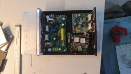
Further your Arylic BP50 is a fully built system, I was recommending to only use the Linkplay wifi board that works with the 4 stream App -
https://www.aliexpress.com/item/100....0.0.9feb7f06Hqsq1L&mp=1&gatewayAdapt=glo2bra
it is for about 17usd on Ali, for trials if you open up the BP50 most likely you will find this Linkplay pcb.
Attachments
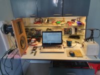
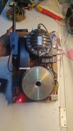
Picture of the Mid + Hi amp and Arylic mini is attached here.
https://www.arylic.com/products/up2stream-mini-receiver-board
https://www.arylic.com/products/up2stream-mini-receiver-board
Attachments
I assembled the first revision of the board and I had the wrong footprint for Q1 (C and E reversed). I can't get the 1452 to start, not even by injecting 1.2V into DVDD and grounding VDRIVE. Without any transistor I get 3.3V out of VDRIVE. Is the chip damaged?
I did a new board revision and got the DSP working, however the AD1938 does not output any signal, only 1.5VDC. Clocks are valid, PLL is locked, reset is high. The codec is run in standalone mode and I grounded the SPI pins, so I can't modify it to read the configuration from it. Any ideas?
- Home
- Source & Line
- Digital Line Level
- ADAU1452+AD1938 DSP crossover