A little over a month ago I mentioned wanting to start a new PCB for the F6 that included some common and not-as-common tweaks that have found there way into the diyAudio community. This idea received positive comments and launched two new PCB designs.
https://www.diyaudio.com/community/threads/zenductor.402522/post-7469793
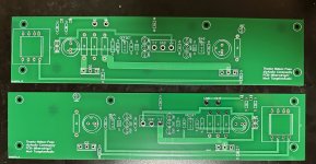
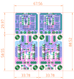
Mikerodrig27 created the PCB artwork for two new variants, one with the standard JFet input stage and one with the Diamond buffer. I have had the PCBs for a few weeks already. It took some extra time to rebuild an old test bed to avoid a prominent 120 Hz hum. Plus I was away on vacay for over a week. All better now.
Cutting to the chase – The performance of the new JFet PCBs has exceeded my expectations. Soldering the green LEDs into the PCB has enhanced the function of their negative temperature coefficient (NTC). There is a more pronounced boost to initial bias current while the amp is cool, then the current drops as the amp heats up. The net effect is that the amp is effectively temperature stable after a half hour, and bias current does not drift appreciably after that.
The new PCBs are built around the Jensen JT-123-FLPCH signal transformers, as standard. We could entertain a dual footprint that included the Cinemag CMOQ series, but my listening experience so far has been wonderful with the Jensens. I don't have any info yet on the lower cost signal transformer proposed for the new F6m variant. I think we may leave that for the diyAudio store.
I chose to build the JFet input version first, with IRFP048 Mosfets. This turns out to be a great combination. I can highly recommend the IRFP048 for future builds by DIY enthusiasts. The store carried these for a while, and they are inexpensive and readily available from Mouser and Digikey.
I am making further mods to the power supply of my test bed and will post more on that and the listening tests soon.
https://www.diyaudio.com/community/threads/zenductor.402522/post-7469793
Mikerodrig27 created the PCB artwork for two new variants, one with the standard JFet input stage and one with the Diamond buffer. I have had the PCBs for a few weeks already. It took some extra time to rebuild an old test bed to avoid a prominent 120 Hz hum. Plus I was away on vacay for over a week. All better now.
Cutting to the chase – The performance of the new JFet PCBs has exceeded my expectations. Soldering the green LEDs into the PCB has enhanced the function of their negative temperature coefficient (NTC). There is a more pronounced boost to initial bias current while the amp is cool, then the current drops as the amp heats up. The net effect is that the amp is effectively temperature stable after a half hour, and bias current does not drift appreciably after that.
The new PCBs are built around the Jensen JT-123-FLPCH signal transformers, as standard. We could entertain a dual footprint that included the Cinemag CMOQ series, but my listening experience so far has been wonderful with the Jensens. I don't have any info yet on the lower cost signal transformer proposed for the new F6m variant. I think we may leave that for the diyAudio store.
I chose to build the JFet input version first, with IRFP048 Mosfets. This turns out to be a great combination. I can highly recommend the IRFP048 for future builds by DIY enthusiasts. The store carried these for a while, and they are inexpensive and readily available from Mouser and Digikey.
I am making further mods to the power supply of my test bed and will post more on that and the listening tests soon.
Attachments
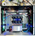
My test bed for the JFet input boards is an old Modushop 4U x 300mm "Jack of all Chassis." This has plenty of heat dissipation capacity to run F6 boards with +/– 24V rails and 1.6A or higher bias current. At 1.6A the heatsinks on my chassis are just warm to the touch. This chassis originally had the Universal PSU board mounted on the inside of the front panel and the 400VA power transformer somewhat in the middle. This arrangement plus an out of date grounding scheme and set of rectifiers was not adequate and required a change to the new configuration shown below. The PSU board and synchronous rectifiers were reused from the original build of my M2x. I must say that they sound better here than they did earlier.
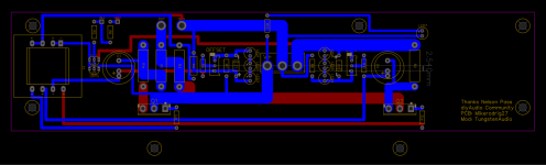
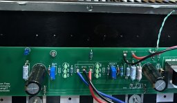
This build is intended to represent one that is accessible to enthusiasts that already have some experience, or those who are fairly new. The channel boards support standard size resistors, but not the larger CM60 in every location. The footprints are well sized for CMF55 and typical 600mW metal film varieties from Vishay, Yaego and TDK. The large 3W resistors were taken from an older stash of Panasonic metal oxide resistors that I had, but newer KOA 3W metal oxide parts have worked well on other boards that I have built recently. Note that the R1 position is split into two footprints. Builders are free to insert a 0.56 Ohm part at R1 and a jumper at R1*, but I highly recommend splitting this into two values: 0.47 Ohm at R1 and 0.0909 Ohm at R1*. This last combination is one that seems to sound especially good with the IRFP048 Mosfets. C1 and C2 are preferred Nichicon MUSE. (Grab some while still available.) R11 and R12 can be from 110Ω to 68Ω. I'm using 68. R7 and R8 are best set at 3.0 kΩ to keep the green LEDs well lit.
The sound. This amp came into sonic focus more readily than several other in the recent year. Not too surprising since the PSU caps were previously used. The Nichicon MUSE caps use a split foil construction that is sadly going the way of many good things. Over the course of half a day, this F6 gave one of the clearest presentation of instrument harmonics that I have heard. Bass was extended and highs were sparkling without being overdone. I have come to expect a liquidity to the sound of N. Pass Class A designs, and this is well preserved. As the original F6 was built around the Semisouth power JFets, it seems to do better with higher transconductance Mosfets in their place. The IRFP048s are an excellent match for the capabillity of the F6. At a rated Vds of 60V, they seem to be in their sweet spot with +/– 24V power rails.
I listened to a couple of my favorite albums and came to notice the only shortcoming of this build. It shares a single PSU in common with both channels. This does ultimately limit the extent of the soundstage relative to the speaker locations. The soundstage exists between the centerlines of the speakers and does not extend above the tweeter locations, though there is a plesent front to back depth. While instruments sound full bodied, there is a slight deficit of spatial definition. I may tend to notice this as I am now used to listening to dual-mono builds. I want to try another tweak to the test bed PSU to see how that works. (Motor run caps) My recommendation for future builders would be to commit to a dual-mono constructions if at all feasible. A pair of ca. 200VA power transformers would be sufficient. Both Antek and Triad have suitable models with 18V secondary windings.
Attachments
Unless there is a rousing chorus for changes, I will make the Gerbers available for the JFet version of the PCBs within the next day or two. The diyAudio community has been part of the general development of the concepts captured in this design. As such, it it already stable and well approved. The community stands to benefit from their work.
I am not familiar with the GLED431. Perhaps the board layout can accommodate such a reference with some ingenuity. My listening tests have not exhibited higher frequency noise, as the LED references are already well filtered. It is possible to substitute a blue LED for one of the green part locations. This would increase the range of gate threshold voltage supported for the output Mosfets.
Hi TA,
You mention the PSU - is this a "standard" CRC design PSU or one based on Mr. Pass's recommended PSU for the F6?
The option for installing Cinemag CMOQ transformers would be cool... some folks might have them from previous / planned projects - but as you have mentioned the Jensen JT-123-FLPCH works just fine and sounds wonderful.
Also thanks to you and Mikerodrig27 for the new PCB design and the efforts. And thanks to Mr. Pass for sharing the F6 design with the DIY community in 2012 - folks continue to enjoy good sound and the hobby of DIY audio!
Last edited:
This wonderful!! Very nicely done, and thank you from the community!
")
I'd echo having the possibility of other transformers, preferably Edcor and CineMag, (if you have to choose just one, Edcor please) for the exact same reason Nelson's new F6m is being made... the Jensen transformers are getting very expensive.
F6 is such a fantastic amplifier, it's great the there are now some options on how to build it. Beautiful!
The PSU that I used was a tweaked version of the standard CRC design sold in the store. I added some extra caps to make it the most it could be.
The PSU is one of the ways a builder can make an amp their own. My original F6 has a gonzo supply based on a pair of dual rail SLB boards and two Antek AS-3222 power transformers.
The PSU is one of the ways a builder can make an amp their own. My original F6 has a gonzo supply based on a pair of dual rail SLB boards and two Antek AS-3222 power transformers.
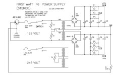
First Watt power supply for stereo F6 attached - excerpts from the F6 article by Mr. Pass:
"It's the same thing except that you can split the RC networks out to each channel separately.
These sorts of filters are very effective in lowering the noise, particularly the higher order
harmonics of the ripple noise."
"It's the same thing except that you can split the RC networks out to each channel separately.
These sorts of filters are very effective in lowering the noise, particularly the higher order
harmonics of the ripple noise."
Attachments
The LT4320 calls for a combination of 1.0 uF ceramic + 10 uF minimum electrolytic. I used 22 uF caps on the rectifier boards.
The 1.0 cap needs to have a low impedance at high frequencies to support what is essentially a miniature SMPS with an internal oscillator in the 8-dip package.
The 1.0 cap needs to have a low impedance at high frequencies to support what is essentially a miniature SMPS with an internal oscillator in the 8-dip package.
Regarding a power supply as mentioned by zman01 above:
This can be built using a pair of the Universal PSU boards from the store and a single 400VA transformer. The trick would be to populate just three of the big capacitor locations on each side, leaving C2 and C3 empty. The boards may then be stacked vertically (in a 4U or taller), or arranged side by side. The two boards are then electrically connected using some nice 16ga wire between the corresponding C2 and C3 mounting pads. I would populate R1 through R3 and R8 through R6 with the recommended 0.47 Ohm, 3W resistors in each board. This will have the effect of a quasi dual-mono PSU as outlined by N. Pass for use in the F6. I tend to prefer the large snap-in caps from CDE (SLPX series) or EPCOS in 18,000 uF.
This can be built using a pair of the Universal PSU boards from the store and a single 400VA transformer. The trick would be to populate just three of the big capacitor locations on each side, leaving C2 and C3 empty. The boards may then be stacked vertically (in a 4U or taller), or arranged side by side. The two boards are then electrically connected using some nice 16ga wire between the corresponding C2 and C3 mounting pads. I would populate R1 through R3 and R8 through R6 with the recommended 0.47 Ohm, 3W resistors in each board. This will have the effect of a quasi dual-mono PSU as outlined by N. Pass for use in the F6. I tend to prefer the large snap-in caps from CDE (SLPX series) or EPCOS in 18,000 uF.
If we were to add an option for an Edcor transformer, this would be the one.
https://edcorusa.com/products/pcw-t...balanced-tri-filer-line-matching-transformers
This is a tri-filar model that may be used in the same way that the Jensen is used in the F6. It would be wired the same way as in the F6m presentation. It is not the same model as used in the M2, and is about half the cost of the Jensen at ~ $24.
Need to check the viability of a dual footprint layout, but I don’t foresee big issues.
There are 2 versions on that Edcor, I assume it is the 600ohm variant. A dual footprint would be good for selection of either brands.
For the JFet input, what Idss did you settle on for these?
Even though the schematic shows IRFP240 for the output devices, as you say the lower voltage IRFP048 will be fine here - as I will be placing an order soon with Mouser, just want to make sure.
What is the adjustment procedure for P1 and P2?
For the JFet input, what Idss did you settle on for these?
Even though the schematic shows IRFP240 for the output devices, as you say the lower voltage IRFP048 will be fine here - as I will be placing an order soon with Mouser, just want to make sure.
What is the adjustment procedure for P1 and P2?
First Watt power supply for stereo F6 attached - excerpts from the F6 article by Mr. Pass:
"It's the same thing except that you can split the RC networks out to each channel separately.
These sorts of filters are very effective in lowering the noise, particularly the higher order
harmonics of the ripple noise."
Looks like diyAudio member Jeff Young has done a power supply PCB:
https://www.diyaudio.com/community/...r-supply-schematic.332356/page-2#post-5670701
Please note that the rectifiers will be off board for this PCB.
- Home
- Amplifiers
- Pass Labs
- The F6 Revisited