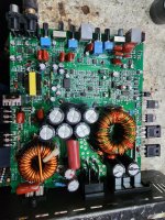
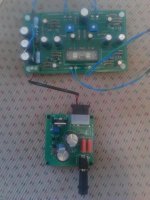
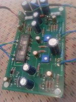
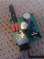
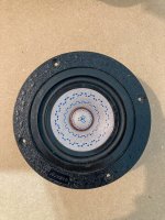
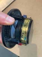
Thanks To Michael Chua

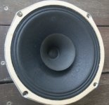
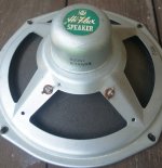
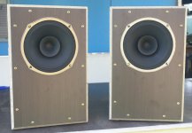
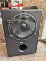
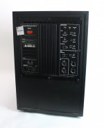
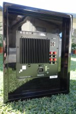
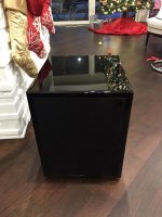
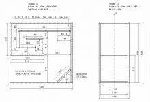
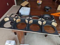
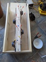
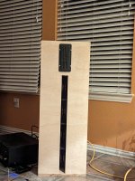
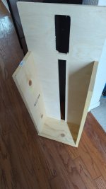
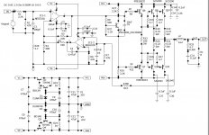
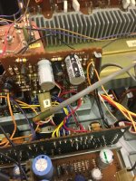
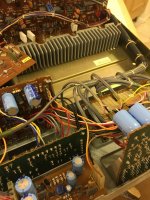
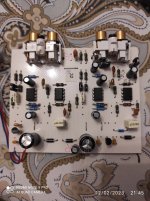
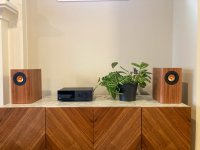
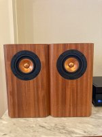
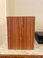
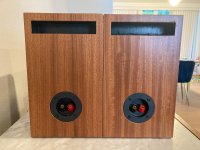
Thanks to Michael Chua for his well documented Kingfisher III design. I made the bandpass sub taller while keeping the same volume. I went a little more exotic and built a trapezoidal enclosure for the mid/HF drivers. The XO is fairly involved but it sounds great!! Great detail without being overly bright and really tight, fast bass. Thanks to Michael for all of his DIY contributions.

Attachments

  • IMG_0505.jpg
    IMG_0505.jpg
    431.2 KB · Views: 162
  • IMG_0506.jpg
    IMG_0506.jpg
    493.6 KB · Views: 153
  • IMG_0504.jpg
    IMG_0504.jpg
    537.3 KB · Views: 142
  • IMG_0502.jpg
    IMG_0502.jpg
    643.4 KB · Views: 179

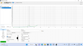
Audiotester and PSU noise measurement

Hello, I ask someone who is well versed in electronic measurements. I would like to roughly measure the noise of a psu and was wondering what WIN software was adequate beyond a high def oscilloscope.
Among various searches I found this article where the author describes the measurement in question, but does not specify in detail. Anyone have any advice on performing like this?
I tried this Audio Tester V3.0 and it seems to me a good software.
I thought of interfacing it to a suitable external sound card and a simple DC blocking circuit for the purpose.

No sound from one of the Rotel RL 870 Speakers?

Hi All.
Hoping for some help.
I have a pair of Rotel RL 870 Speakers.

When I first set them up for a listen, there was no sound out of one of the enclosures.
The only way in was via the woofer hole on the baffle.
As well as the fixing screws the woofer appeared glued on. I couldn't budge it so this project sat around for 6 months.
I recently re focused and was able to budge the woofer from the baffle with a piece of timber and a mallet.
I carefully tapped the woofer around its circumference, and without damage was able to break the grip of the glue.

I tested both the woofer and tweeter with the battery (1.5v) method on the terminals.
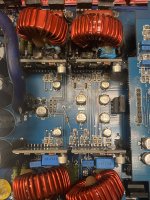
Both drivers are alive and moved outward when +ve terminal aligned with +ve battery.
A careful look at the crossover and solder points hasn't revealed any obvious broken joints in the wiring.

Any thoughts for further tests?

Also the thick internal cabling is marked "SUPRA".
Should I replace this with the CAT5 solid core wiring while I'm at it?
Also the capacitor might need to be replaced?

Attachments

  • Rotel RL 870 1.jpg
    Rotel RL 870 1.jpg
    155.1 KB · Views: 225
  • Rotel RL 870 2.jpg
    Rotel RL 870 2.jpg
    234.7 KB · Views: 255
  • Rotel RL 870 3.jpg
    Rotel RL 870 3.jpg
    269 KB · Views: 253
  • Rotel RL 870 4.jpg
    Rotel RL 870 4.jpg
    329.7 KB · Views: 242
  • Rotel RL 870 5.jpg
    Rotel RL 870 5.jpg
    310.2 KB · Views: 247
  • Rotel RL 870 6.jpg
    Rotel RL 870 6.jpg
    445.9 KB · Views: 238
  • Rotel RL 870 7.jpg
    Rotel RL 870 7.jpg
    424.6 KB · Views: 245
  • Rotel RL 870 8.jpg
    Rotel RL 870 8.jpg
    380.9 KB · Views: 273
  • Rotel RL 870 9.jpg
    Rotel RL 870 9.jpg
    522.1 KB · Views: 253
  • Rotel RL 870 10.jpg
    Rotel RL 870 10.jpg
    450 KB · Views: 242

SNR from noise density

A bit if a gap in my expertise here.
OK, My amp has an output of 22V RMS
Spice tells me my noise density is 112 nV/sqrt Hz
Divide 112 by sqrt of 20K or 141, I get .794nV

Here is where I go wrong. I am off by a factor of 1000.
If I plug this into 20 log (22/.794 ee-9) I get 208.

Of I do 20 Log (22/.794 ee-6) I get 148 dB which is the believable value.

I tried to follow Cordell in his spice section and I believe his example is off by 10, so even more confused.

Maybe I am totally confused. 😕

HK Citation V schematic?

Neither Google nor the forum search is my friend today.

I've been looking around for a REAL Harman Kardon Citation V amp schematic, but all I can find in the Sams Photofacts version (like this one). It's everywhere. ...and no power supply included.

I also have the assembly manual that is floating around the internet, but curiously, it does not contain a schematic or any diagrams other than a drawing of the bottom plate, which isn't too exciting. The schematic is mysteriously absent, like Watergate minutes.

Anyone got the real schematic kicking around?

..Todd

Creek Destiny: Right channel thuds on switching inputs and Right channel DC Servo offset increases with volume

Hi Folks,

Any help is appreciated. I'm seeing two issues in the Right channel that seem to be related. However, without finding the root cause I cannot be certain and have listed them separately.

1. There's a slight thudding sound in the right channel upon switching inputs. The thud gets louder when switching inputs at higher volume levels. The thud is barely audible at my typical listening volumes. I can hear the thud through the headphones when the speakers are off, and through the speakers when they're turned on. I can corroborate the thuds with spikes in DC offset measurements across the speaker terminals.
  • For the left channel, I'm detecting a much much lower DC Offset spikes, and the thudding is mostly inaudible.

2. The DC Servo output (pins 8 and 9) increases when I increase the volume. For instance, the voltage from U101 (pins 8 and 9) WRT Ground = 100 mV at minimum volume (7 o'clock), and 130mV when volume is increased to 11 o'clock. DC Offset measured at the speaker terminals stays below 5mV, this tells me the DC Servo is still doing its job in spite of the voltage increase in the DC Servo.
  • The left channel DC Servo U1 (pins 8 and 9) WRT Ground = 1mV and does not change when increasing the volume.

Recent troubleshooting and work I've done on the amp
  1. Replaced the mute relay - No change.
  2. Right channel: Replaced all diodes and the IC (TL074CD) in the right channel DC Servo.
  3. Right channel: Replaced input transistors, diodes and zener diodes.
  4. Issue 1 happened before changes 1-3. I just recently stumbled on the issue 2 after changes 1-3.

Do issues 1 and 2 fall under what is considered normal for this amp? Both don't really impact my listening experience. But the concern is something is awry somewhere in the right channel from the input to the output.

Schematics attached.

Attachments

Help identify 3.5mm connector

Hi, can anyone help identify the female 3.5mm connector based on a couple pics?
Sony xb950n1

I wanted to try replacing it but can't find a 4 pin for sale, matching the pic.
Hoping 3.5mm repairs are somewhat common, I'm in the process of removing it.
Could I use PJ-321? https://www.amazon.ca/PJ-321-Stereo-Female-Connector-Headphone/dp/B07SMZCXKW
Thanks

Attachments

  • 20221205_202644.jpg
    20221205_202644.jpg
    573.5 KB · Views: 120
  • 20221205_202745.jpg
    20221205_202745.jpg
    424.5 KB · Views: 115

JVC H810 Dead

I just found a pair of JVC H810 headphones in what appear to be mint condition. Plugged them in to a known source and…nothing. No static, no super quiet sound, nothing. I peeled back the plug and all seems fine, worked the cable from plug to phones listening for sound. I’ve never had both sides of a pair of phones go completely dead….I’m stumped. I’m not sure how to open the cans and online info is sparse. I know these to be really nice sounding phones, really advanced for their time. Thoughts, ideas?

Interest for GB for MarcelvdG valve DAC

[special=]%[/special]This thread is to gauge interest in PCB's and/or major parts for MarcelvdG's valve DAC as published in Linear Audio 13.

Discussion thread here:
Valve DAC from Linear Audio volume 13

Article for purchase here:
Linear Audio | your tech audio resource

Design package download here:
Downloads | Linear Audio

Pictures here:
http://www.diyaudio.com/forums/digital-line-level/166807-dac-gallery-12.html#post5065812

Note that this is a relatively expensive project, the Jensen signal transformer is $USD137 for 1 piece, and the FPGA board is $EUR225 for 1 piece, let alone all other components, so please consider that before expressing interest.

At this point, just please cut and paste the following text into your post and add your name and quantities desired:

Member PCB set Transformer FPGA
leadbelly 1 1 1

PP 6V6s in Class AB2

6V6s in Class AB2

Here is a similar version of the amplifier proposed by Miles P back in 2007 (Tee-Vee T00b Amp). This one from the Summer of 2001. Altho the project results were posted on RAT at that time I never authored an article for publication. Real work got in the way. The transient results did appear in the Nov 2003 issue of AudioXpress later as part of another project. And here on DIY from time to time.

This amplifier was not built with listening in mind. Or as a work of art. It is strictly experimental & satisfied some of my curiosities.

I had certain objectives in mind for this project.

  • PP 6V6s in Class AB2
  • NFB to the upper grids of a differential cascode stage
  • Transient performance of the amplifier while powered by a limited power supply
At that time 6V6s were still plentiful. And I had several in my stash. To run in Class AB2 the PP 6V6 loadline has been adjusted to 6.8K running thru a Hammond 125E Universal OPT. The 6V6s are driven by CFs in a 6BQ7. The top 4BQ7 of the Cadscode avoids H-K problems by running on its own 5V supply. The B+ is 338V.

The idea for the internal NFB originated with Bill Perkins of PEARL. On a business trip to Calgary I made a point of visiting Bill. He was working on many projects, one of them included NFB from the output plates back to the screen grids of a earlier stage.

I reasoned that NFB back to the screens would be loaded by the pentode screens, why not try instead the upper grids of a PP cascode stage. The cascode stage is a differential pair of 6BQ7s with a long tail of 100K down to -150V. So the internal NFB is taken from the 6V6 plates. And the resultant internal NFB is ~8 db.

A Hammond 271X power transformer is sufficient to run the 6V6s in Class A. The rectifier is a full bridge of 1N4007 diodes so that both +ve & -ve voltages are available. The +ve filter is a CLC of 10 microF, 5H & 100 microF. The –ve filter CRC of 10 microF, 1.5K & 10 microF. Then 25K & a VR150.

I ran tests both using the amps internal supply & with an external regulated supply.

What would happen in the PS if the amp suddenly was required to pass a large transient signal? In some ways this was similar to what happens to a guitar amp when driven hard.

Attached are some of the test results I got recently when I pulled the amp off the shelf for another look. The Scope/SA is a PicoScope 3224. I used a Differential Probe for most of the measurements. For the burst traces the PS sag is the blue trace, the test signal One KHz at 10 Watts.

And it does sound very good. Bench tests are a very good predictor of success.

Attachments

  • 026 Cascode Amp A.JPG
    026 Cascode Amp A.JPG
    710.7 KB · Views: 293
  • IMG_1383 Cascode Amp Bottom A 14W E Flash  Labelled.jpg
    IMG_1383 Cascode Amp Bottom A 14W E Flash Labelled.jpg
    437.1 KB · Views: 385
  • Cascode Amp H.jpg
    Cascode Amp H.jpg
    74.1 KB · Views: 376
  • 6V6GTA 14W 4 PushPull C 6W.jpg
    6V6GTA 14W 4 PushPull C 6W.jpg
    60.4 KB · Views: 352
  • 20220102-0003 Burst.jpg
    20220102-0003 Burst.jpg
    104.3 KB · Views: 247
  • 009 One Watt 345V Int Supply D%.JPG
    009 One Watt 345V Int Supply D%.JPG
    94.8 KB · Views: 230
  • 007 10W 324V Int Supply D%.JPG
    007 10W 324V Int Supply D%.JPG
    91.7 KB · Views: 218
  • 006 15W 311V Int Supply D%.JPG
    006 15W 311V Int Supply D%.JPG
    102.5 KB · Views: 227
  • IMG_1383 Cascode Amp Bottom A 14W E Flash  Labelled.jpg
    IMG_1383 Cascode Amp Bottom A 14W E Flash Labelled.jpg
    437.1 KB · Views: 214
  • 001 SMPTE at One Watt w IMD Sidebands Identified C.jpg
    001 SMPTE at One Watt w IMD Sidebands Identified C.jpg
    54.5 KB · Views: 254
  • IMG_6383 to 6384 Work Bench 12W E.jpg
    IMG_6383 to 6384 Work Bench 12W E.jpg
    621.8 KB · Views: 261

AD825 module from LC Audio

Hello everybody,

I am new in here. Nice to meet you all. I have question regarding to the AD825 module from LC Audio. For analog circuit in cd player, does the module really superior to the AD825 opamp? I mean comparing between the module and the AD825 opamp (just only the chip) Is it worth more money to spend? AD825AR from Newark is about $4 each which AD825 module from LC Audio is about $14.

Thanks

RCA tube amp (7199 & 7027A) 30W - NFB question

Hello Guys!

After some years I would like to assemble a tube amp again. I would like to rebuild an "old" RCA circuit 1:1 and listen to it.

Now I have everything necessary for this at home. I see on the schematic that a feedback connection is hooked to the 16ohm connection of the OPT.
My OPT here has "only" an 8 Ohm output. My question to you tube experts: how do I have to adjust the values of the feedback parts so that it also works "correct" at 8 ohm ?
Your much appreciated help on this is higly welcome 😍

1643124219479.png


1643124233818.png

TAJ's Harman Kardon Citation V rebuild thread

This thread will chronicle the rebuild of a 1961 Harman Kardon Citation V I picked up cheap on eBay a few years ago. There's not a lot of quality documentation available on the internet for this amplifier, so part of the intention here is to help fill that gap for future rebuilders. Your feedback and participation is of course essential.

Speaking of poor documentation, if anyone has a decent copy of the *complete* original assembly documentation for a Citation V, I'd like to chat with you. There's only one copy floating around the web and it's missing all the assembly diagrams and pictorials, which makes it tedious to identify and trace all the parts. There's also a Sams Photofacts guide floating around but it looks like a low rez scan of a fax of a photocopy, all done with 1970's equipment, the pictures are pretty difficult to read. And there is an error in the Sams schematic which doesn't inspire (in me at least) much confidence in the rest of the information.

Before anyone mentions it, yes I know about Jim McShane, and his offerings will likely be an important part of this rebuild as it progresses.

About this particular amp, its chassis is not in great condition, it has some rusted areas on the front of the deck that has damaged the silkscreened text in places, and the faceplate has a heartbreaking set of deep scratches across it that will be challenging to deal with. I'll be looking for ideas there. The guts have already undergone some (poorly executed) minor updates and/or repairs by the looks of it. The transformers all look like they are in great condition, thank heavens.

The plan is to completely strip the amp down to its essentials and refresh and renew as much as possible. I have photographed the guts from every possible angle, but I won't upload all those photos here unless there is some specific need to show something. I used to be a technical illustrator, and I like to draw using Adobe Illustrator almost as much as I enjoy working on tube amps, so expect plenty of drawings and diagrams where appropriate.

If this thread is of any interest, stay tuned...

..Todd (TAJ)

Attachments

  • pic1.jpg
    pic1.jpg
    58.3 KB · Views: 643

Sydney's AMP Center

Just reading a little about this project today. Anybody here work on it? Very exciting to see an existing structure modified to a more modern one in this way. Would like to see this or similar approaches like this used around the world. Really cool indeed ... must has been pretty great to be working on such a project from a labor standpoint.
https://www.cnn.com/style/article/australia-quay-quarter-tower-skyscraper/index.html

SMSL DO200 MKII don't read file DSD

Good morning everyone.
I recently purchased the wonderful SMSL DO200 MKII DAC.
This DAC mounts the brand new XMOS xu316 usb chip.
I need to ask you for help because it doesn't read native dsd files.
Up to Dsd256 files it reads them only as DoP, while Dsd512 files it doesn't read them.
I connected it via USB port to an Asus mini pc with Windows 10 and I use Foobar2000 as a player.
I describe below the complete configuration I made: Installed dac drivers downloaded from SMSL official site. I have downloaded and installed the latest version of Foobar2000 (v1.6.14). I have downloaded and installed the Asio software version 0.9.4. Start Foobar2000, install the following addons (foo_input_sacd.fb2k (v1.5.1)), (foo_out_asio.fb2k) and (dsd_processor).
I pretty much followed the guide on the SMSL site. https://www.smsl-audio.com/portal/news/detail/id/697.html
Why doesn't the dac work well with dsd files?
I hope someone can help me.
Thank you.

Moode Bluetooth - no audio ?

Hi all,

I'm new to Moode, having only set it up a few days ago. Dead impressed.....

Raspberry Pi 3 Model B Rev 1.2 / HiFiberry Digi+ All works perfectly out of the box with the Digi+ - So moved on.

I have a pair of Bluetooth Speakers, they appear to connect., (they announce as such..) but no audio? (JVC XS-D629BM)
(my BT soundbar has the same synptoms)
Other info: Speaker pairs with my phone and work perfectly....

mpd output is changed from local to Bluetooth. I then start to play a radio station, - but no audio...


Is there any other debug I can use/any ideas what's going on ?

Many thanks
Mark

Dec 11 22:36:58 moode systemd[1]: Started Music Player Daemon.
Dec 11 22:37:00 moode upmpdcli[1134]: :3:src/mpdcli.cxx:148::MPDCli::startEventLoop: already started
Dec 11 22:37:32 moode bluealsa[7458]: /usr/bin/bluealsa: D: dbus.c:59: Called: org.bluealsa.Manager1.GetPCMs() on /org/bluealsa
Dec 11 22:37:32 moode bluealsa[7458]: /usr/bin/bluealsa: D: dbus.c:59: Called: org.bluealsa.PCM1.Open() on /org/bluealsa/hci0/dev_17_1A_F3_97_EB_06/a2dpsrc/sink
Dec 11 22:37:33 moode bluetoothd[7449]: /org/bluez/hci0/dev_17_1A_F3_97_EB_06/fd6: fd(32) ready
Dec 11 22:37:33 moode bluealsa[7458]: /usr/bin/bluealsa: D: ba-transport.c:868: New transport: 14 (MTU: R:672 W:716)
Dec 11 22:37:33 moode bluealsa[7458]: /usr/bin/bluealsa: D: bluez.c:1068: Signal: org.freedesktop.DBus.Properties.PropertiesChanged()
Dec 11 22:37:33 moode bluealsa[7458]: /usr/bin/bluealsa: D: bluez.c:1104: Signal: PropertiesChanged: org.bluez.MediaTransport1: State
Dec 11 22:37:33 moode bluealsa[7458]: /usr/bin/bluealsa: D: ba-transport.c:750: Starting transport: A2DP Source (SBC)
Dec 11 22:37:33 moode bluealsa[7458]: /usr/bin/bluealsa: D: sbc.c:114: SBC setup: 48000 Hz JointStereo allocation=SNR blocks=16 sub-bands=8 bit-pool=51 => 345000 bps
Dec 11 22:37:33 moode bluealsa[7458]: /usr/bin/bluealsa: D: ba-transport.c:1032: Created new thread [ba-a2dp-sbc]: A2DP Source (SBC)
Dec 11 22:37:33 moode bluealsa[7458]: /usr/bin/bluealsa: D: a2dp-audio.c:644: Starting IO loop: A2DP Source (SBC)
Dec 11 22:37:33 moode bluealsa[7458]: /usr/bin/bluealsa: D: ba-transport.c:789: PCM resumed: 10

Resample dev modules.

I'm building a DIY digital path router. It's not a mixer, although it will down/up mix. It's not a DSP although it will do basic EQ. It's not really even about music, although music will be played through it. It's just a big hub for connecting the plethora of USB, 3.5mm jack and Optical devices into a common set of buses ending up with an N to N digital router.

I can feel the hatred already, but I'm not even going "High Fidelity" from the start. V1.0 will be 48K 16bit across the board. Which brings me to my question.

Given that audio clocks, well, I'm not going to go chasing baller xtals and trying to make clocks play nicely. Life is too short. I have been well advised by those "in the know" in such aspects that clocks can't really be simplified away.

So, unless I want to handle all the potential nasties that clock skew and drift WILL cause in software, or I want to invest a decade learning to program a "real" generic DSP, my best option seems to be Jelly bean resample ICs. In my case they won't be resampling, same format both sides, but what they will do is resample across clock domains.

I see a few posts in here around similar, but usually either buying audiophile preassembled units with DAC/ADCs and/or all the high end stuff in tow.

I'm wondering if anyone has any experience with the basic reclockers/sample convertors. I'm looking for the consumer grade market, similar to, say the level of the PCM5102 or PCM2706, which is basically just setting some pins for your preferred format and/or let it auto detect as slave on both sides, whatever.

I won't exclude chips that do highend formats, as long as they also do basic DVD quality 48K. If V1.0 works, then V2.0 may well have a specific "music" path for a bit higher, like 24/96.

I've tried trawling through Farnell and TI's site, but browsing datasheets is never easy. I also tried trawling AliExpress for clones of other modules, but I found too wide a range on price and functionality, so .. I came here to ask.

Crown PZM mics and their benefits

I will introduce this subject by offering what I have found so far:

https://drive.google.com/drive/folders/1orfIKUxQK18SwvABKMz07LF0Le8HiHgi?usp=sharing

The file Crown_Mic_Memo_issues_over_22_years.pdf in there is an archive of an informative discussion held over many years on the benefits of PZM mics.

I bought two of these mics new, and I have been testing them both in my home studio https://goo.gl/maps/2C8uA2abQhG3tQ5E6 and in an open field, and also comparing them against the Vanguard v44s gen2.

I will post those test tracks later if there is interest.

I have found that the stereo effect using only interaural time delay by placing the two mics on the floor with capsules 18 - 20cm apart is very good in my very non-reverberant studio. Recording with that mic placement in an open field, as long as it's quiet enough with low wind, yields even better results.

The mic capsule spacing in the ORTF style of microphone placement is usually 18cm. Experimentally, I have found 20cm to be just right when I put the two mics on the floor, both pointing the same direction. The PZM mics are omnidirectional, so my mic placement does not enhance the stereo separation like ORTF does when it aims the two cardioid mics in different directions, and yet, the stereo effect is still convincing and sounds natural.

The mic placement used in https://en.wikipedia.org/wiki/The_Trinity_Session is not the same, as it uses directional mics placed very close together on the floor, so it solely relies on inter-channel amplitude difference to establish the stereo effect like a pan pot on a mixer, and not interaural time delay in what I'm doing. What it does have in common with what I described above of putting two PZMs 20cm apart on the floor is the rejection of floor bounce, hence it picks up only long time delay echoes from the church's walls and ceiling, and avoids short time delay echoes that come from sound bouncing off the floor.

Are these mics used still in the recording industry or small scale non-commercial efforts like mine?

Is there interest from folks in my area in Orange County in southern California in doing further tests with these mics in configurations different from what I have done above?

Is there interest in doing recordings of small ensembles using my mic placement or some other placement using the PZM mics, either in my home studio or in an open field?
  • Like
Reactions: kevinkr

Power calculations for class B amplifiers

I'm working on a few class AB amp designs at the moment and got tired of having to rifle through references to find these. So, I decided to put things together into one set of notes. I'm hoping it's useful for others as well.

This is a pretty standard derivation of the formulas, but the presentations by Dr. Cristina Crespo referenced in the article made things a lot easier. If you're looking for a good introduction to electronic engineering, you could do a lot worse than check out Dr. Mateo Aboy's YouTube channel, where Dr. Crespo's videos are hosted.

This is also the first time I'm using asciimath. Yeah, you can generate prettier results with TeX, but asciimath is about a billion times easier to write!

Bitten by the bug.

Hello,
i recently refurbished a pair of Revolver Purdey speakers for someone else. I replaced everything as they were twenty years old and the woofers were visibly cracked and worn. Having completed this project and getting a lot of satisfaction from it I am tempted to take on a new challenge; build a set of speakers from scratch. ( I am good at woodwork and there was very little woodwork in the last project). The tweeters, Vifa D19TD-05, from the last project look to be perfect. They are twenty years old though. Are they still good, or would it be foolish to put them in a new build?

I plan on making a set of bookshelf speakers, the Classix II, https://sites.google.com/site/undefinition/bookshelf-speakers/classix-ii with the Dayton DC160 and the above mentioned Vifa tweeters. The last project involved floor standing speakers but the consensus was that the whole configuration would work better in a smaller cabinet which is why I want to make bookshelf speakers this time.
Is MDF the best material to use? What about solid hardwood like oak or beech?
If it's MDF do you use veneered MDF or do you apply veneer to the finished product?
Can I use the same crossover I used in the last project?

Regards
Talksome

RTR SSR Speaker Protection GB 4

I have been getting a bit of interest lately for the Gen 2 RTR SSR’s to be available again now that they are sold out.

Schematics for Gen4 here: https://www.diyaudio.com/community/threads/rtr-ssr-speaker-protection-gb-4.378742/post-6971387

Description of the project is here:
Ready-to-Run (RTR) SSR DC Speaker Protection and Delay GB

891926d1604979168-ready-run-rtr-ssr-dc-speaker-protection-delay-gb-58344f39-83d0-4306-b8a0-95dfbb8b2c42-jpeg


I would like to start a pre-order list for the 4th group buy. Once we reach 10 people ordering a pair of 20 units, I’ll take pre orders and get these manufactured again.

Please add your name and number of boards you are interested in below.

For example:
Code:
Name      Qnty       Country
xrk971      2             USA

For folks who sign up for the pre-order, price will be $50ea and free shipping in the USA.

For those who buy later after the pre-order phase, price will be $60ea. I’m sorry prices have gone up due to parts shortage.

Update Nov 12, 2021: order 3 pairs and get free shipping worldwide.
Pre-order for 3 Pairs of GB4 for RTR SSR Speaker Protection | Etsy

Restoration and modding of a vintage FT75B tranceiver.

A friend gifted me this antique ham radio rig several years ago. It has been stored at home by those years, more. It is dated about the early 70's.

I restored it and modified it replacing several of the BJT's in the signal path and crystal oscillators enhancing the sine wave by them generated and reducing the noise and a slightly increase in its sensitivity. Note that this set ISN'T A HIFI DEVICE. It has been designed for ham radio use mainly, as a SSB (Single Side Band) or CW (Morse code) and the audio BW is severely reduced in order to limit the RF BW thus increase the number of channels in a ham band and concentrate the output power in only one of the dual AM sidebands. The unwanted sideband and the carrier is eliminated increasing the overall efficiency. Audio BW is restricted to spoken words and is from 300 to 3000Hz at best. A powerfull crystal filter is included at the IF stage to cancell out the unwanted SB and the carrier at TX and reducing the noise at RX. Unfortunatelly one of the front knobs was lost prior to own it.

Already I posted here the modification of the audio amplifier inside the rig and replace the original AN214 (burnt) with a pushpull of 2SK941 small power MOSFET's.

The tube final power amplifier is still inoperative. I need to build a multivoltage power supply including 250V for the 12BY7, about 500V for the 6DQ6's plates (paralleled), regulated 150V for 12BY7 & 6DQ6's screens and -100V for the biasing of the grids. The relay below depicted switchs the antenna to RX or TX stages and simultaneously maintain both grids bias well below the cutoff level in order to avoid interference in RX and tubes overheating. The front panel includes a switch that power up the heaters if it is wanted to transmit.

Originally the rig has 3 crystal channels per ham band although only one was provided by factory, installed. There is a switch that enables a rear input for an external VFO (Variable Frequency Oscillator), a means to cover the wide of each ham band.

The rear connectors are obsolete and difficult to find. So they were removed and replaced with commonly available ones. One of them has a free contact to ground in common to the band selector, on each band which enables an external power amplifier or VFO to act in synchronizity with the rig and a free changeover from the TX/RX relay. This has been replaced by a sub D 9 pin unit, and as I win some free pins, I hook a regulated 9V to it to power the VFO stage alone. The input of the external VFO now is carried by means of a DIN connector 5 pin where I added a 12V out for the VFO amplifier and adder. The jack for the CW key was removed as I hate Morse code, and in its place, a 100K pot is fitted to ajust externally the mic gain. Such a control was inside the mic amp and not available for the user. A 3.5mm mono jack was added too to use an external speaker, not included in the cabinet. A speaker terminal was included in one of the changed connectors but I prefer it separately.

I designed my own VFO using the 3 FM sections of it for each ones of the 3 Clapp oscillators made about 3SK40 dual gate MOSFET's. The rig is so designed that with 3 oscillators it can cover 5 bands, sharing part of the oscillators for two bands. A secondary winding in each oscillator coil (made inside of new TOKO 10mm cans) are serial wired and added to feed a 4th 3SK40 that decouples the oscillator from rig and the cable linking them. Each source is choosen by the connections in the 9 pin connector above mentioned. The 2nd gate of all MOSFET are all tied together to a voltage divider giving them about 4V stabilized, the point where usually those devices gives its best transconductance. There isn't risk of oscillator's mutual interference as only one of them is powered at a time.

The schematic of the entire apparatus, is of course, very large and available in the web in the scans of the original user manual. Those for the VFO, PSU and for the audio amp will be available soonly.

Attachments

  • Rig.jpg
    Rig.jpg
    409.9 KB · Views: 94
  • Rear.jpg
    Rear.jpg
    298.1 KB · Views: 99
  • VFO_proto_left.jpg
    VFO_proto_left.jpg
    408.3 KB · Views: 88
  • VFO_proto_right.jpg
    VFO_proto_right.jpg
    420.2 KB · Views: 86
  • Xtal_Filter.jpg
    Xtal_Filter.jpg
    301.4 KB · Views: 87

Aleph 2 project burning problem

Hello,

i am building an Aleph 2, and have a problem:


At the moment i power up the amp:

R11 and R12 are burning up in flames.
Q3 breaks, Z5 also.


The rest of the board seems to be ok.

I tested this two times, thought i had a defect Q3 while assembling the board. But it was the same effect.

The schematics (and the part numbers) are the same as in the original Pass documentation. I checked everything about 5 times and can´t see the mistake i made.
My rail voltages are a bit higher than in the originals, i have +-49V instead of the +-45V. Can this 4V more cause the Problem? (I don´t think so)


Now i am absolutely out of ideas what the problem could be and ask you for your help.


I attached my schematics and board layout.


Regards, Martin

Attachments

LEDs and amp draw

Does anyone know about LED strip and amp draw?

I have a 5m strip and it says it draws about 900mA per meter. So for a 5m strip it should draw about 5A at 12v.

I've put it onto 12v and it only draws .8A

Am I measuring it wrong?

See photo:

Put meter in series with the positive wire. Which I have done countless times with other things. I'm just confused it saying about 5A when it draws .8A

Cheers

Attachments

  • 20221210_233136.jpg
    20221210_233136.jpg
    365.1 KB · Views: 96

Vintage Henry Kloss Advent Loudspeakers

I've just inherited a pair of 1970's Henry Kloss Advent Loudspeakers.
They're in original condition, but with the cabinet veneer & covers missing.
Also the crossovers (iron core inductors, sandcast resistors and electrolytic caps) appear original.
I've done a battery test on all drivers and they're all live.
As I need to downsize I'll be making them available to a collector.
Should I just clean them up and offer them as is, or should I freshen them up with walnut veneer, and poly caps?
Looking for your ideas.

Cheers C

Attachments

  • Advent Loudspeaker 1.jpg
    Advent Loudspeaker 1.jpg
    268.8 KB · Views: 507
  • Advent Loudspeaker 3.jpg
    Advent Loudspeaker 3.jpg
    497.1 KB · Views: 493
  • Advent Loudspeaker 4.jpg
    Advent Loudspeaker 4.jpg
    427.9 KB · Views: 1,224

Ultra-steep crossovers (like 100dB/oct) - smart or crazy?

I was casually reading about the Joseph Audio Pulsar out of curiosity based on someone's strong endorsement on ASR. In the review they mentioned the crossover was around 100dB/octave or more. The idea has occurred to me, since with DSP, you can do that as easily as any other filter... but I was under the impression that a smooth handoff was preferred to avoid jumps in directivity. I have seen few posts talking about more than 48dB/oct before.

But if directivity is a good match at the crossover frequency... any other reasons you wouldn't want a sharp transition like that? According to the reviewer, they did a stellar job with the xover so that you couldn't tell where it was by listening.

Assuming you nail the FR match and directivity... (a big assumption, certainly) am I missing anything? Seems like an interesting way to stop worrying so much about center-to-center distance, at least...

Brionvega "RR 126" Radiofonografo stereofonico from 1965 schematic wanted

Attachments

  • Castiglioni RR-126 front left.jpg
    Castiglioni RR-126 front left.jpg
    36.9 KB · Views: 462
  • Castiglioni RR-126 front wood.jpeg
    Castiglioni RR-126 front wood.jpeg
    21.3 KB · Views: 437
  • Castiglioni RR-126 front.jpg
    Castiglioni RR-126 front.jpg
    58.2 KB · Views: 422
  • Castiglioni RR-126-front-II.jpg
    Castiglioni RR-126-front-II.jpg
    123.9 KB · Views: 449
  • Castiglioni RR-126-top.jpg
    Castiglioni RR-126-top.jpg
    117.8 KB · Views: 420
  • Brionvega ts502.jpg
    Brionvega ts502.jpg
    27.5 KB · Views: 336
  • brionvega_ts502_schema1.jpg
    brionvega_ts502_schema1.jpg
    76.8 KB · Views: 645
  • brionvega_ts-502_1964_zanuso_sapper.jpg
    brionvega_ts-502_1964_zanuso_sapper.jpg
    10.7 KB · Views: 445

Power Pack for Dual CS 415-2 Turntable?

Hi All.

I have a Dual CS 415-2 Turntable with missing power pack.
This model features external power pack rather than onboard.
The Dual specs for their power pack is: 12V DC, 150 mA

I picked up a non Dual Power Pack with the specs: 12V DC 1.25A

I listened to a video on power packs.
It was indicated that with mA/A values, there is a pull rather than a push.
If the power pack has greater mA/A than the end device requirement, the device will only pull what is required.

Bottom line, the turntable plays records at incorrect (slower) speed.
Do I have a power problem or is the turntable malfunctioning?

thanks C

MA12070p Schematic Review

Hi guys,

i am currently creating a small Wifi Amp. I want to ask if someone can review my Schematic. The Board itself does work already. Rev.2 i currently in progress. I changed the DCDC to something with a higher Frequency. Do you have some Ideas or Improvements?

Rev 2:
  • Via stitching for ground plane
  • DC/DC to higher Frequency
  • Route the output signals on one layer [without Vias, if possible]
  • PBTL Jumper
  • More Via for audio line
  • Add better cooling vias for the amplifier IC, it overheats, improve thermals with a proper ground plane
  • Switch the Power regulator (XC6220)
  • Remove the unnecessary logic level converter
  • Implement reverse polarity protection
  • LED: WS2812B
  • Change layout, from left to right: DCDC ESP32 AMPLIFIER, and not DCDC AMPLIFIER ESP32, or move the dcdc to the bottom right far away from the amplifier.
1651527743278.jpeg

Attachments

  • Like
Reactions: ricyuyc

Premium SRC & PCM to DSD converter AK4137EQ Evaluation Board (DIY)

Hi All,

Recently, on the market is available premium SRC AK4137 from AKM (Asahi Kasei Microdevices).
The chip is interesting since it is not only the SRC but also converter from PCM to DSD and DSD to PCM
I wanted to test it, but AKM don't have any Evaluation board or Starter kit for this chip.
So I decided to design my own Evaluation board.


AK4137 features:
-PCM / DSD conversion function
-conversion from 2.8/5.6/11.2MHz DSD to PCM format, and vice versa.
-Maximum Sampling Frequency, Bit rate: PCM768kHz/32-bit, DSD256(11.2MHz)
-DR: 186dB
-THD+N: -150dB
-Sound Color Digital Filter: 4 types

Evaluation board features:
- hardware or software configuration mode
- SPI or I2C mode
- galvanic isolation of I2C bus (option)
- gerenal purpose I/O (I2C extender)
- low noise LDOs (LP5907 or LP2985)
- separate LDO for XOs
- different option for master clock (External clock, crystal, XOs )
- clock sourse can be selected by I2C extender
- serial termination rezistors (I2S bus and clocks)
- IDC or U-FL connector for clocks an I2S bus
- different footprints for decoupling capacitors (SMD and THT option)
- reset by switch or I2C extender
- PBfree

Schematic, render of PCB and real PCB photos in attachment.
I received PCBs yesterday and I didn't have time to assemble the first piece.

If anyone is interested I have some spare PCBs.
Chips are now avaliabie in DigiKey.

Best regards
JarekC

Attachments

  • jc1001render.jpg
    jc1001render.jpg
    363.7 KB · Views: 1,998
  • jc1001pcb.jpg
    jc1001pcb.jpg
    862.2 KB · Views: 1,917
  • JC1001sch.pdf
    JC1001sch.pdf
    46 KB · Views: 889

Blaupunkt BEA80 / TA7270P ic

Hello.
On my desk I have Blaupunkt BEA80 car eq with 4ch amplifier.

I did the recap and it sounds much better than it did before (2 channels, other 2 have bad ICs).

I want this unit in my 91 Camaro because it fits it's time period nicely by the look.

I have some scenarios planned, final will be decided based on your anwsers and further testings.

Now I'm deciding between:
1.) Using this unit only for looks and feeding input signal in just for the vu meters.

2.) Using this unit only as eq, just feeding signal thru the eq part.

3.) Replacing TA7270P ics to get all channels working.

4.) Removing all amplifier components from the PCB and modify with different IC. There isn't much space so I was thinking about using single car hifi 4ch ic, something from the early 2000s, on it's own pcb.


Now my questions are:

1.) Did anyone had such unit and can tell me what it's sound quality should be?

2.) Can anyone tell me about TA7270P sound quality?

3.) Do TA7270P tend to get bad like STK for example?

4.) Are there TA7270P chinesse knockoffs online like for STK?

5.) Can anyone tell me about the quality of eq section?


My plan would be to use it only for the looks, but I don't want to feel like idiot when someone will try to move the faders and nothing will change 🤣😗😗

I'm leaning the most towards using this unit only as eq and to use another amplifier to power the speakers... but again I don't know if it will harm sound quality.


I'm attaching the schematic and photo of the unit:
Screenshot_20221211_095629_Drive.jpg


16707518661217170870400755568581.jpg

Attachments

PCF 802 KIT - PHONO RIAA Preamplifier - for sale

PCF 802 KIT - PHONO RIAA Preamplifier

Kit for building PHONO RIAA Preaplifier with tubes. Is a stereo variant - for two channels one single boards

Variants:
  • only tubes - 25EURO + 15 Euro shipping to EU. I am sending to EU only.
  • PCB - tubes - sockets - 50EURO + 15 Euro shipping to EU. I am sending to EU only.
  • complete - all components and tubes - assembly - 65EURO + 15 Euro shipping to EU. I am sending to EU only.

Note: NO power transformer, NO soft start function, no power supply module

Attention, electronic tube mounts work with dangerous voltages that can cause death if you are not careful and do not know how to use them.

For more details, please send me PM.

Link with photos: https://postimg.cc/gallery/yHGGGJB
  • Like
Reactions: Airhead

Seas CA26RFX vs A26RE4 as 10 in woofer for Acoustic Suspension 2way?

Any experience on Seas driver CA26RFX as a 10 in woofer in an acoustic suspension build? I’ve searched but not had great yields. Seas does note a sealed box volume of 1.35 cu ft for it - at least in the Madison’s page. That’s fairly well in line with the cabinet volume I’d like to use it with, pairing with a Seas exotic tweeter crossing at 1500Hz. I've seen numerous threads on the A26RF4 from the Seas A26 kit in discussions, including as a basis for a Devore O/93-96 clone, but am wondering if there's any background on this other 10 in.

Windows 11 includes WSL (Linux) with audio system access

I've been working under Linux to do audio processing, e.g. DSP and loudspeaker crossovers, for some years now. The Windows Subsystem for Linux (WSL) has always been interesting and I played around with previous versions, but the deal breaker was always that there was no (native) access to the audio devices on the computer. Evidently Windows 11 is changing that.

This is great news. Some things are just easier to do under Linux, and then some software is only available for Windows. Now I can get both, the best of both worlds so to speak, with one OS.

Supposedly Windows will create a Linux environment for the Linux app to run in, currently using kernel 5.10, which a very recent one. Not sure how they solved the audio link, but I hope to test it someday.

The only negative I see is that for Win11 to run on the computer, the hardware must include a type of security chip, the "Trusted Platform Module" (TPM) version 2.0. I doubt that my gaggle of Linux Intel miniPCs include it, which is kind of a bummer.

Anyway, I thought I would start this thread to talk about audio under Win 11 via the Windows Subsystem for Linux. If anyone does get some first hand experience with that, please post about it here.

JC2 preamp board clone please help me bias it

Hey guys I'm stop pre amplifier module here that claims to use the original second-hand transistors and fetes from the original amplifiers whether that's true or not who knows but it was stated in the seller's add and description now this board is way different to all the other boards I can find on the net first impression I thought it sounded a little harsh hurt the is a little bit and was just not all there so some spark or moment of clarity I suddenly had at the time told me to run a 6 J1 12-volt tube buffer after it and somehow it really cleaned up the module I've tried using the tube buffer on other boards and preamplifiers I've got and for some reason this buffet and this JC to clone board just go together like milk and coffee but upon my first board arriving left and right channels were a little uneven having a cyst that it was not my volume pot I decided it was the borg and should possibly try to give biasing and adjusting the DC offset ago as I would imagine the way these things are put together in China and by who is putting them together that they just let them together hope it works and post it to the only reference or instructions I can find for biasing the jc2 board is from a different design similar circuit just slightly different but same principle I will include the picture and diagram of that method and as you can see in pictures below of my board on trying to adjust if anyone could point out which resistor I should be measuring my voltage drop across and maybe give me a little bit of insight into the configuration differences between these two boards and what I should do to mind to achieve what I have to thank you
16707862951713810980404180777912.jpg
16707864989717763047394164774922.jpg
16707861860585846921852297832451.jpg

Help

I'm an old guy with lousy hearing and little knowledge in audio electronics. To watch TV I have to use wireless headphones. Right now I use Sony bluetooth headphones connected to my Samsung TV. Trouble is every time I need to use them I have to click and scroll through several steps (25 clicks) to connect. Secondly, the bluetooth signal range is awful. If I wander far from the TV I lose the signal and have to go through the whole connection process again. I want to get an audio transmitter that will connect to the TV from an optical port. Am I correct in thinking that I will only have to pick up the headphones from the pedestal and turn them on to listen and the signal range will be much improved? The greater the range the better. And lastly, if I connect the transmitter to the optical port will the TV speakers be disabled? I don't want that. I will be grateful for suggestions..

Hi all. Digital Audio routing box w/ MCUs.

First post! I joined here as I think I'm wearing my welcome on the electronics forum 🙂

There may be more experts in here to maybe nudge me away from peril or my own stupidity and in the more correct direction.

I set myself some requirements for how I personally want my audio served up.

A desktop system which will provide
  • multiple USB digital inputs,
  • a single 3.5mm/RCA analogue 'aux' in.
  • multiple 3.5mm/RCA analogue outs.
  • Option of a single digital output, tos, spdif TBC.
  • Have 2 (or more) internal 'buses' with EQ, minimal processing (mix/balance/eq).
  • nice to have, knobs, buttons and a LCD screen UI.

Without building anything I can find cheap rubbish for about £150 that will work for 75% of those requirements, but will end up fissiling and scratcing an failing after a month. I can also find studio grade monitor/cue routing boxes for 1U racks with multiple inputs and outputs and EQ + 4 or more headphone amps. However these cost £3k +

I'm not looking for "professional grade audio" or even a "professional grade mixer". Just something that allows me to maintain pure digital audio until the last possible second when it's off loaded at the best quality reasonably achievable to an amplifier. In the case of the headphone amp that will hopefully be a PCB trace away from the DAC.... if I can't find a beefy enough I2S headphone amp with more than 500mW power.

To that end. Unless required to "cast" up in bit width for calculations all audio will remain 16 bit. Unless there is a good reason, such as word alignment, buffer alignment or other prevalent reason, all audio will be 48K stereo.

This is cheating. Yes. It's the only reason I consider it achievable. If I wanted to do this to support all the possible bit widths, sample frequencies and all manor of formats and endpoints ... it would be better off just using a massive DSP chip and becoming long term friends with it's datasheet by the bed side!

By standardising all streams to the single 48k 16 bit stereo, and cutting the buffers to be the standard 1ms from USB and I2S I can treat audio buffers as cookie cutter items. All of them will be 192 bytes containing 96 samples. 48 left, 48 right. <- this is subject to a trade off between efficiency/stability of processing larger buffers versus latency (and increased synchronisation requirements) of the same.

Ideally, running a SINGLE I2S clock on the project will prevent buffer creep/clock skew on all but the USB end points which will need realignment from time to time. (present test setup loops the buffer in about 30 minutes with a 24.576Mhz clock on a breadboard, not ideal as that includes about a minute where both DMAs are reading/writing the same frame!).

The current outline architecture is really hinged on one question. Do I want to continue to use an MCU as the USB endpoint. I have had far, far too many issues with the driver code surrounding USB Audio Class on STM32. I still haven't solved the fact it will not respond to the incoming audio stream about 4 times out of 5. I have to continually reset the MCU to get it to pick up the stream. Obviously a driver timing issue there, it's missing an important packet or it's receiving it when it's not ready for it and the PC does not send another. I expect forcing an endpoint reset on power up or on USB cable insertion may help sync them. The other option is using a hardware IC like a PCM2706. That has the issue where "consumer audio" ICs, tend not to like 24.576Mhz clocks. They tend in fact to have a max I2S MCLK of 12Mhz. So until I can get my hands on one (shipping and IC supply issues) and test a few prototypes out I can't know if it will be worth seeking an alternative slower clock or continue with the MCU approach. The ideal here would be for the PCM2706 to be running with an external I2S master clock, and for it to do the USB sync'ing or asking the host to respond to ITS clock. That would completely free me from doing any reclocking / reframing of audio streams - a huge bonus.

The decision above knocks on to the internal bus architecture. I2S is great and all, but it's slow as it forces you down to the sample frequency domain for transmission. I mean that kinda is the point of it. However the I2S ports are really just SPI ports with a few additional signals. For the internal bus I am free to use SPI at a MUCH faster rate than the I2S. A 48K@16bit stereo I2S stream is about 1.3Mbit/s The native hardware SPI bus on even the small STM32F411 runs at 50Mbit/s. (well, 48Mbit/s if you need USB 48MHz clocks too). A single frame of I2S can be transmitted and received in less than 250us on that bus.

High level: Multiple input end points can "dump" their audio packets (pre-gained) to one or two internal buses. These buses are mastered and processed by a more beefy MCU such as a STM32H7. Processing will include down-mixing - simply mixing two streams together, parametric EQ per bus, not per channel, not unless I have LOTS of free horsepower, which I doubt. I won't be writing perfectly optimised filter code and will probably be re-calculating biquad coefficients on the fly.

Finally, of course, output routing. Each internal bus can be assigned to any output.... or more practically the buses will send their audio out regardless and each output endpoint is free to pick up that bus or not.

4 x Input - i2s -> 2x Bus mixer STM32F411 - 50Mbit SPI -> 2x Bus processors STM32H7 -> 4 x i2s output.

If the PCM2706 avenue hits a dead end, I can drop the i2s bus and just use SPI bus there. The exception would be the aux analouge in which will have to have it's i2s stream rebussed to SPI.

I already have breadboard prototypes of mixing an ADC stream with a USB stream, including buffer alignments. I have a list of prototypes to put together and test. Each sub component or bus topology has a set of prototypes to test it works as expected or not as the case might be. Each helps me decide which path to take.

The hardest part is steming from my lack of formal mathematics training/study. I just don't speak maths. That creates an issue when you come to researching EQs and filters, which the main populus in that field are electrical engineers who insist on calculating everything from scratch every time and forcing you to sit through listening to them explaing it in derivatives each time. I can find OS libraries I can pilfer/borrow, it's just finding the easies to port to ARM DSP biquads.

FS: tubes, pcb and components for Pete Millett's DCPP Amplifier

I have those for years, realize will not be able to finish it, so it's your chance to have it, for less.

include:

PCB (the big red one), 4 big sockets
10 6HJ5, 6 6GU5
resistors and caps to stuff the pcb (can't guarantee all of them, but >95% at least)

I know the 6HJ5 is getting quite expensive now, so how about US$300 for all the things above? Shipping exclude.

Magnavox CDB473 CDM-2 mechanical clacking noise

Hi All:

The CDM-2 mechanism in my Magnavox CDB473 has started making a single acoustic CLACK noise when the PLAY button is pressed after inserting a disc. The noise doesn't seem to affect the unit's operation however, and I am able to easily set the laser power and focus offset adjustments as documented in the Service Manual. The noise is due to the pickup swing arm hitting its end of travel as it moves toward the center of the CD. The pickup has what looks like a small grey bumper next to the lens that seems intended to cushion the end of travel, but it doesn't seem to be doing its job. It is possible this bumper has broken and is missing the piece that would do the stopping, but I haven't been able to find any photos of this detail online. Does anyone have any insight into what the CDM-2 inner end stop bumper is supposed to look like?

Incidentally, I'm only using the player as a transport to deliver S/PDIF to a Museatex (Ed Meitner = EMM Labs) Bidat DAC.

Thanks!
DC

Thick Film Hybrid (not monolithic) Integrated Circuit Amplifier - Overview

Sanyo's STK series knows everyone - there were and are still a number of other types and brands, that are not as well known:

1) BC SVI3505A (BC Power Module - no exact informations)

2) Kenwood TA2030/TA2031
Eugen Gurskij Elektronik - ICs
Kenwood TA100WA
Audioklinik: Die Meisterwerkstatt für HiFi Klassiker ob Transistor oder Röhre in Düsseldorf.
Kenwood Hybridendstufen - und es gibt sie doch

3) Matsushita/Panasonic STK8040 (Technics new class A)
http://i14.ebayimg.com/01/i/07/4d/58/db_2.JPG
http://www.maxdat.eu/_data/Random/STK8040.jpg
audio-technics.fm.interia.pl/technika/amptech.htm
Amp model - hybrid model
Matsushita/Panasonic "RSN 36S5 A" "RSN 36S5 B" (Technics)
eBay Österreich: RSN36S5B RSN36S5 B Amplifier IC NEU (Artikel 130368471680 endet 19.06.10 13:13:41 MESZ)
data sheet information for RSN36S5A from www.ecadata.de

Attachments

  • Kenwood TA2030-2040JPG.JPG
    Kenwood TA2030-2040JPG.JPG
    12 KB · Views: 2,012
  • Kenwood TA2031.jpg
    Kenwood TA2031.jpg
    143.5 KB · Views: 2,070
  • kenwood_ta-100wa open.jpg
    kenwood_ta-100wa open.jpg
    136.9 KB · Views: 2,086
  • Kenwood TA100-200 W-WA six pack.jpg
    Kenwood TA100-200 W-WA six pack.jpg
    887.5 KB · Views: 2,244
  • Kenwood TA100WA.jpg
    Kenwood TA100WA.jpg
    104.5 KB · Views: 1,904
  • Sanyo STK850 Technics newClassA.jpg
    Sanyo STK850 Technics newClassA.jpg
    6 KB · Views: 747
  • Technics Hybrid RSN36S5B.jpg
    Technics Hybrid RSN36S5B.jpg
    131.8 KB · Views: 655

GB: Round #9; Fo-Felix AC Filter

We're on round #9!!!

5x20mm fuse option added for Euro buyers

Prices have increase some, but luckily it's minor


So over the years people have asked about the old version, made by someone else.

It's probably time for an updated one. This one is a bit different. You may notice it does not have following capacitors after the choke. I have tried both ways, and my preference is strongly without the following X2 capacitors. Also the capacitors prior to the choke are not varied in size because overall capacitance is more important - and they won't randomly resonate with each other.

The other major change is the addition of bypass resistors for the chokes. These don't ruin the filtration, but they do a good job of quieting the chokes that can get excited by different combinations of things on the mains.

fo9unnamed.jpg


Gen1 w/comoco's
IMG_1974_1_22.jpg


Here's how it is different in settling time from the original.
Fo_felix_vs_felix.png


Here's a comparison between resonances.
Fo_felix_vs_felix_resonance.png


*2oz copper PCB (1oz is standard)
*Weco 983ZD terminals, copper alloy and can accept 2 wires for daisy chain. These are also safer, particularly if you use solid core wire that otherwise likes to make cold solder joints you can't see.
*X2 rated capacitors for safety, 4x 0.47uf. They are alternated for CFC (capacitor field cancellation).
*Discharge resistor for X2 capacitors
Coilcraft Comoco choke w/fuse or Bourns 8120/8121-RC choke w/o fuse & 15/16A/20A() max sockets
*Fuse clips are beryllium copper 3AG & 5x20mm options
*120/230v operation (parts & pcb)
*Mounting holes are sized to work nicely with M3 screws and standoff kits
*Size: 2.25x4.25in

The Weco 983ZD are preferred terminals, but not always available as individual sale. For this reason I'm going to include them in the price of PCB, so that I can meet min order requirements for them and save everyone the shipping.

Price: $14ea ($10 per filter board, $2 per Weco, 2 needed per board)

Shipping: $11 US, priority USPS box
$20 CAD
$22 General international padded envelope (prices may vary due to a crazy world)

If ordering over 4x boards there may be an additional $10, depending on destination.

Need 32 filter board commitments to order.

#10

danbmellow 10​

B&C DE250 on Dayton H812

Was looking at some horns allowing a low ~800 Hz crossover for the DE250.
Came over this French site which shows fantastic extension and linearity with the Dayton H812 horn:

Grand Comparatif de Compressions 1 pouce - JustDIYIt !

FR-DE250.jpg


But Ampslab (Michael Chua's) measurements of the same combo doesn't give the same picture at all... Even if you look past the smoothing differences.

https://ampslab.com/blog/2020/06/12/dayton-h812/

H812_B3.gif


The measurements of the D220TI matches up pretty good tho :scratch2:

Any experiences with this horn out there?

Alpair 12pw Fullrange?

Hi Guys
Just wondering if anyone has tried the Alpair 12pw on its own. I can see it is discribed as a Mid woofer but the treble seems to roll off fairly gently.
Also I have a pair of A6P which I found to be too lifted in the upper regions for my taste, can anyone compare these to the regular fullrange A12p in terms of smoothness and character.
Thanks Simon

Classic monitor designs?

Hi.

Post here if you have constructed or found designs on internet about classic monitor designs.

Here is couple of what I have found.

http://www.troelsgravesen.dk/3WClassic.htm

http://www.troelsgravesen.dk/CSM_KIT3.htm

I don't seek for slim floorstanders or small monitors but bit larger monitors which have bass grunt by their bigger cabinet volume and wider baffle. And yes, they can be bigger than those examples. 8-12" bass would be fine 🙂

If you have seen cabinet construction with thin walled enclosures, please post here. I think some british speakers are made of thin material and they sound lively.

GE 8136 OTL tube headphone amp idea

Hello,

Was looking through my assorted tubes and found a handfull of GE 8136 Beam Tetrodes that i would like to build an OTL headphone amp with.

Not sure if anyone has actiually used this tube for an audio amp before but looking through the datasheet they seem to me at least like they could work.

First things first, i am not looking to make something necessarily objectivly good.

This is just to have some fun by designing an amp of my own with something thats not been done to death already like the 12A-whatever/ECC tubes. They make for great amps but thats not what this project is about 😛

The goals with this are:

  • To be able to drive my 50 Ohm headphones
  • Having a good time designing and building
  • Learning about general tube amp design
  • Learning about the specific design conciderations for Beam Tetrodes
  • Designing and building a clean PSU that can be used in this and later projects

I'm fairly new to designing amps, especially tube ones(Done a small amount of solid state stuff as cource work) so i expect this to need a lot of work. I havent gotten much further than looking at the datasheet and speculating but i threw together a sketch of what i am thinking so far.

I have no idea what to do with the screen with an OTL tetrode so for now in the sketch its just voltage divided to sit at ~125V plucked from the datasheets typical operation.

Other than that i am thinking of a V+ = 200V-300V and Grid Bias = -1.5V as these regions seem fairly linear with regards to the expected input amplitudes( <50mVrms / <0.14Vpp ).

Looking this over one last time before posting i realise that this might have a "huge" voltage output(~70V) and that Ra should be shrunk to something much smaller but i am not entirely sure, its late here so please enlighten me on this matter... 🙂

I have attached a sketch of the topology that came to mind first but it is probably going to need quite a bit of work. Happy to hear your thoughts on it as long as its not "wow this is dumb" or "why would you build this" but do feel free to point out any flaws in a constructive way!

Attachments

  • 8136_tubes.jpg
    8136_tubes.jpg
    211.9 KB · Views: 245
  • OTL_8136_v0.82.jpg
    OTL_8136_v0.82.jpg
    236.9 KB · Views: 260

Esoteric D02 Does not work usb

Hi! Help with troubleshooting the usb receiver on the esoteric d-02 DAC. The problem is that it is not detected by the computer. The drivers don't help. Windows writes that an unknown device. Everything works on another DAC of the same type. I called the whole board, all of it. I checked all the voltages and found different voltages at two points, otherwise everything is absolutely the same in voltage. I attach a photo of the board. In the photo, I marked in pink near the chip where there are voltage discrepancies. Also yellow and pink are marked relative to each other, the voltage with the working board is also different. I also checked nec 2801c-4 by moving it from one board to another, it works, the problem is not in it.

Attachments

  • IMG_20221209_211715_edit_145038490544671.jpg
    IMG_20221209_211715_edit_145038490544671.jpg
    808.4 KB · Views: 77
  • IMG_20221209_211729_edit_145317874852897.jpg
    IMG_20221209_211729_edit_145317874852897.jpg
    487.1 KB · Views: 73
  • IMG_20221210_220013_edit_144624245728370.jpg
    IMG_20221210_220013_edit_144624245728370.jpg
    516.2 KB · Views: 69
  • IMG_20221210_220120_edit_144792036099035.jpg
    IMG_20221210_220120_edit_144792036099035.jpg
    526.1 KB · Views: 63
  • IMG_20221210_222010.jpg
    IMG_20221210_222010.jpg
    488.1 KB · Views: 61
  • IMG_20221210_222024.jpg
    IMG_20221210_222024.jpg
    536.7 KB · Views: 71

3 way utilizing C-note drivers

Hello all. Long time lurker, first time poster. I've had this account for quite awhile but decided to try and utilize the knowledge that some folks may give me in constructing a new speaker.

Long story short, I grabbed a pair of C-notes from PE this year and while I quite enjoy pretty much everything coming out of them, I feel bass and mid bass isn't rendered quite as well as I'd like, and frankly I think I'm just not that big of a fan of small speakers. I think I mostly purchased these out of boredom rather than to fill a use case. I've gotten to the finishing stage and it's been a disaster, the first time I'm attempting to paint a speaker. I have lost all interest in finishing the cabinets as I know they will not come out to a satisfactory level, I very much prefer wood veneer and have great luck in applying it, unfortunately do to the rounding I did over the whole cabinet veneer isn't really an option anymore.

Anyway, I'm at the stage where I'm considering woofers to take over the lower end of things and utilize the DSA135 and ND25fw for the mid and top end. I have a measurement mic and DATS, so far only utilized to make crossover modifications to already built DIY kits by importing measurements into Vcad.

Right now I'm looking at the peerless 830668 as a great candidate. I'm curious to hear your guys thoughts on a this idea and if you have any recommendations for 8"-10" woofers to utilize in this build.

Turntable RIAA preamplifier, old turntable upgrade

turntable Arija-102 upgrade, dont have distortion analyzer to confirm spec.
Phono RIAA Preamplifier
POWER SUPPLY
VsSpecified Voltage
±18​
V
IQQuiescent Current
13​
mA
IMPEDANCE
ZIInput Impedance(MM*)
47​
kΩ
ZIInput Impedance(MC*)
100​
ZOOutput Impedance min.
600​
INPUT NOISE
Input Voltage Noisef=20 Hz to 20kHz
4.3​
µVPP
GAIN
MM*1kHz
40​
dB
MC*1kHz
60​
dB
AUDIO PERFORMANCE
THD+NTotal Harmonic Distortion
0.001​
%
Amplitude Deviation from RIAA Response
0.2​
dB
* MM(moving magnet cartridge) / MC(moving coil cartridge)
can get one here : https://www.ebay.com/itm/304526368495

Attachments

  • 20220521_121043.jpg
    20220521_121043.jpg
    798.3 KB · Views: 79
  • 20220614_074546.jpg
    20220614_074546.jpg
    317.7 KB · Views: 80

Gate drivers HS shorting G-S after power up

Good day folks,
I have two different amplifiers with different output FETS and drivers but similar symptoms.
  • Firstly i have a Soundigital 8k, older silver unit, uses IR2010 gate drivers and IRFGP4072 outputs, came in with burnt power supply.
  • Secondly a Soudigital 3k, silver unit, uses IRS20957S and A2 outputs. came in with burnt output filter caps.

Both amplifiers, no shorts found , both were repaired. when powered up they both go into protect, when checked the HS outputs are shorted G-S, all other outputs test fine. After the rails are discharged, the HS output test open. i've replaced the drivers in both to no avail.

Anyone came across a similar problem?

Question on trouble shooting opamps, pre-amps, and tone control.

Im still pulling my hairs out trying to get some boards I purchased to give a clean signal out. Last night I had this thought maybe its in my approach.
Im feeding a signal say 1V 1Khz into the input and tracking it thru the circuit.
So far only one board has given me a clean output signal.

My questions.
1. Maybe my mistake i that Im not connecting anything on the output of these boards. Im confused. would putting a load on the output help stabilize the signal.
What kind of load should I put ?. A speaker ? A resistor ? A working amp ? I was using a speaker but then a friend told me you never put a speaker on the output of an opp amp. Or if you do it should be a tiny speaker say from a headphone. What if the design has already taken care of this i.e. it has a 100 ohms resistor on the output.
2. What contributes to the oscillations. Power supply op amps or poor component choices with the op amps.
How to I separate my quest i.e. power related noise vs circuit noise. One way I feel is to find a circuit where there are zero oscillations and use the power from there to drive the circuit that is acting up.
I found a nice circuit on a op-amp tester in Elektor.
In fact last few weeks have been going thru old elektor mags. Looking at their articles on filters, amps, speakers etc.
Found this link you guys may enjoy. Good articles on Frequency filters, op amp testers, various amp and pre amp designs. Some good OG articles by Self.
https://ia600804.us.archive.org/20/items/ElektorMagazine/
  • Like
Reactions: alighiszem

High Power Hybrid Amplifier

I would like to share with you the result of my new hybrid amplifier.

The my first version of this my amplifier was made in 2010 then i made some improvements.

The new version uses a very simple and cheap tube driver with 6Z51P or D3a that can deliver 40Vrms with a single tube.

The distortion is about 1.5% at 33Vrms so about 150W on 8ohm.

This project collects all the experiences made in these years then it born with all these characteristics:

  • no global feedback design
  • passive components without any compromise on any section
  • only few parts on the signal path, only 3/4 active components
  • very short signal path
  • very low output impedance (near to 0.1ohm) for high damping factor (near to 80)
  • very high output current, output devices able to manage 60A
  • high output power to drive any loudspeakers including ESL, 140W on 8ohm and ?W on 4ohm
  • very good slew-rate
  • large frequency band, near to 1.5MHz for the IRF820 configuration
  • high separation from power supply for all the sections
  • power supply separated for each channel
  • zero noise
  • ultra low distortion in the current amplifier
  • zero dc offset, dc servo loop
  • no fuse on the signal path
  • no relay on the output signal
  • only a single vacuum tube for the voltage amplifier
  • only one interstage capacitor on the signal path
  • high input impedance 110Kohm
  • high voltage gain able to be driven directly by any source
  • voltage stage and driver stage working in pure class A operation
  • high efficiency near to class AB
  • compact chassie

Attachments

  • Sch2022b.gif
    Sch2022b.gif
    20.5 KB · Views: 190
  • Ibridone_2022_thd1_8ohm.jpg
    Ibridone_2022_thd1_8ohm.jpg
    51.4 KB · Views: 175
  • Ibridone_2022_freq_8ohm.jpg
    Ibridone_2022_freq_8ohm.jpg
    71.1 KB · Views: 166

Best 15 inch woofer for my system

Good day
I’m building 3 way system :
Hf- faital hf10ak+ sth100
Mid- radian 950 + k402 horn
And LF i can’t choose between AE TD15M and Faital 15pr400
There is faital dealer in my country, so i can buy pair of 15pr400 for 460 usd
AE is 750usd for pair + 300 usd shipping to Ukraine with tax
I can pay the difference between them but i need to know does it worth it?
Are AE woofers much better?
Thanks in advance and happy New Year!

Schematic for Logitech Z Cinema

Hi

I've got an old Logitech "Z Cinema model: 980-000085) and despite the cheap looks it appears to be fully active system.
There´s separate amps for tweeters (AB?), mid/lows (TDA8920) and sub (TDA8922).

Its born with and USB-interface and I would like to convert it to analog inputs.

The central ADC is 4-channel and I'm pretty sure thats 2 channels for sub and 2 channels for satellites.
I have not traced all circuits, but there is a PCB-section that look a lot like an active cross-over implemented with opamps.
I'm hoping that all cross-overs are implemented in HW, -and that DSP-functionality can be bypassed completely...

I would say that based on HW this system must have some potential, but it would be VERY helpfull to have complete schematics.
I've tried all my normal goto-sites for schematics and service-manuals with no luck.

Any ideas?

Kind regards TroelsM

7.1 or 5.1 amp\receiver

Hi there,

I would like to know if there's anything out there that must have 7.1 or at least 5.1 minimum outputs and with 7.1\5.1 analog inputs that is class D and must be dirty cheap, don't need too much quality or too much power, just something OK as it's only mostly for gaming to connect to my PC soundcard analog outputs.

And I need it to have separate volume control per channel and crossover settings pear each pair of speakers (Front, Side, Rear and center separately).

I have a Receiver that does this all but it's way too big for my room, it's inside my wardrobe for years since I bought it and I don't need any of the TV and many other extra inputs\outputs that the receiver has...

ps: I don't even know what I'm looking for but never found such thing yet and like I said must be super cheap like around 100€ max even if I have to buy used and must be from EUROPE.

Thank You
guily

Acoustic Research tonearm...

Acoustic Reasarch tonearms. Made by Jelco, not sure which model, were used on Acoustic Research turntables like EB-101 and similar.

Purchased 10 years ago by some closed USA audio repair store. New, but not complete, without lift. ( Jelco JL-45 fits perfectly.) Otherwise totally functional, antiskate, wiring, mounting base..good bearings, all metal aluminum/bronze.

Have a few of them, god price for DIY, if someone is interested, send me a PM.

Regards

Attachments

  • DSC_0934.JPG
    DSC_0934.JPG
    570 KB · Views: 371
  • DSC_0935.JPG
    DSC_0935.JPG
    721.6 KB · Views: 383
  • DSC_0936.JPG
    DSC_0936.JPG
    679.2 KB · Views: 357
  • DSC_0937.jpg
    DSC_0937.jpg
    338.7 KB · Views: 376
  • blogar eb101j.jpg
    blogar eb101j.jpg
    14.1 KB · Views: 394
  • ODg0MDEzYjlmNGU2YWQ4ZDg2MGVhMjAwMzA2MGQyNGaTVZGkeya9vblSOqEQxa13aHR0cDovL21lZGlhLmFkc2ltZy5jb20v.jpg
    ODg0MDEzYjlmNGU2YWQ4ZDg2MGVhMjAwMzA2MGQyNGaTVZGkeya9vblSOqEQxa13aHR0cDovL21lZGlhLmFkc2ltZy5jb20v.jpg
    37.5 KB · Views: 270
  • Like
Reactions: yogiDIYbear

Maybe low Q speakers don't suck as bad as it would appear in sealed cabinets.

Yes Qts below 0.5 yields a start of roll off that is higher (given the same Fs) than higher Q which results in a higher -3dB frequency. But looking a response simulations the difference in -10dB points is not as great and I suspect that the -10dB point is really the more pertinent figure especially when room gain is taken into account. But on top of that many times the low Q drivers tend to have lower fs which further mitigates the issue. It may even be that the low Q slope more closely matches the slope of room gain in normal "leaky" rooms.

I may need to do a bit of experimentation. Have you guys found the bass extension of low Q sealed enclosures to be really lacking or not as bad as it looks? Thoughts?

Es9038pro DVDD help

Hello,

Need some help understanding what i do wrong here.

Long story short.
We have made some PCB for the 9028PRO chip. Works perfect and sounds good.
For 1.2V DVDD we use this: input 5V -> 1uF X7R-> ADP-151 1.2V -> 1uF X7R. This provide the 1.2V to chip and we have some 0,1uF around the legs of the chip.
ADP-151 can provide 200mA output current and input volt can be up to 5.25V and 9028PRO spec say 82mA at the DVDD. I have looked at DimDIm's post and I know that higher input kHz takes up to 200mA, But we only use 44.1kHz.
All fine up to here.

Anyway, we tried to put in a 9038PRO in the same PCB (AVCC is ok and can handle up to 600mA).
With the 9038PRO the ADP-151 can't provide to output 1.2V, We get something like 0,9V.
So our first ide was that for some reason 9038 need more then 200mA current for DVDD. In the spec it say something like 128mA.
But if we "break" the PCB circuit and lower the input volt to ADP-151 to around 3.7V (from 5V to 3.7V) it's working ok and we have 1.2V.

How can that be? Lower input gives ok output (1.2V), but 5V input only gives 0,9V output.

Sorry if the "story" is impossible to understand....

BR//

Daniel

Salas L Adapter circuit on Raspberry Pi footprint Board

I made some Salas L adapter circuits on placed them on a raspberry pi board outline for my music servers that run Moode Audio. I have made some new ones with a changed component footprint positioning to better suit the other boards in my stack, So the old ones are for sale if anyone is interested. I will list them as I swap out my old ones.
The 2 white connectors supply 5VDC. one has a ptc fuse on it. My Pi running Moode only drew about 500mA. If you were drawing more you might need a bigger heatsink. It was supplied by 9v dc by an old linear wall pack. It has a toggle switch on the 9v input for off and on.

Attachments

  • 1.jpg
    1.jpg
    164.2 KB · Views: 282
  • 2.jpg
    2.jpg
    197.8 KB · Views: 258
  • 3.jpg
    3.jpg
    203.8 KB · Views: 221
  • 4.jpg
    4.jpg
    166 KB · Views: 262
Projects by fanatics, for fanatics
Get answers and advice for everyone wanting to learn the art of audio.
Join the Community
507,484
Members
7,873,799
Messages

Filter

Forum Statistics

Threads
405,559
Messages
7,873,799
Members
507,484
Latest member
Giuseppe1971