Take a look at the mfr data sheet for good information.
https://www.ti.com/lit/ds/symlink/lm1875.pdf
https://www.ti.com/lit/ds/symlink/lm1875.pdf

What's wrong with data sheet layout? Why build 30 years old chip amp? Especially when the chip you got is likely fake?
Maplin-Electronics-1.. - World Radio History https://worldradiohistory.com/UK/Mapelin/Maplin-Electronics-1989-02-03.pdf
Maplin-Electronics-1.. - World Radio History https://worldradiohistory.com/UK/Mapelin/Maplin-Electronics-1989-02-03.pdf
I got 2 IC's from TME (Europe) they seem to be original, paid about 4.5 euro 1 IC.
As for the question why a 30 year old chip amp? i want to make a 30 w (maybe a little more if possible) amp for the sub.(i also have some A2030V IC's)
Thanks for the PDF 🙂. i will read it.
The link here :
https://www.tme.eu/ro/details/lm1875t_lf02/circuite-integrate-rtv-audio/texas-instruments/
As for the question why a 30 year old chip amp? i want to make a 30 w (maybe a little more if possible) amp for the sub.(i also have some A2030V IC's)
Thanks for the PDF 🙂. i will read it.
The link here :
https://www.tme.eu/ro/details/lm1875t_lf02/circuite-integrate-rtv-audio/texas-instruments/
Also to use a TDA2822 or 4558P? for a basic preamp. Thanks for taking some time to answer my questions.What's wrong with data sheet layout? Why build 30 years old chip amp? Especially when the chip you got is likely fake?
Maplin-Electronics-1.. - World Radio History https://worldradiohistory.com/UK/Mapelin/Maplin-Electronics-1989-02-03.pdf
Jim, take a look at this link which composes a simple PCB that fits many of the older chip amps. The fake board issue is discussed.
The LM1875 and the newer TDA units are available on Mouser. There is a family of these amps, pick one that is best fit for your requirements. Chip amps are fussy about layout so maybe not the best for NewBee if that is what you are.
The LM1875 and the newer TDA units are available on Mouser. There is a family of these amps, pick one that is best fit for your requirements. Chip amps are fussy about layout so maybe not the best for NewBee if that is what you are.
tda2050 datasheet .
or if not happy take a look here: https://www.circuitbasics.com/video-how-to-design-and-build-an-amplifier-with-the-tda2050/
or if not happy take a look here: https://www.circuitbasics.com/video-how-to-design-and-build-an-amplifier-with-the-tda2050/
Attachments
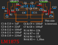
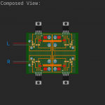
Hello, took 2x LM1875T/LF02 for a BTL configuration as seen in the PCB design.
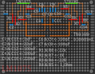
I "baked" the PCB today and works pretty well, i dont know how to calculate the noise tho. (barely audible on tweeter)
The LM1875 has less bass than the A2030V IC's. (The A2030V is 40 or more years old and i did not found any datasheet for it so i used 30v and 40v on the LM1875 IC's).
Yes the heatsink is grounded and yes both IC's are isolated from the heatsink.
Conclusion :
IDK someone with more knowledge and a little time to spare has to check the board design. For me works more than fine.
Attachments

I'd be careful with those long leads to the ICs.
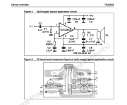
The reason your thread saw little action is likely that your board layouts are hard to read. The LM1875 will work well if you build the circuit shown in the data sheet. It's available from TI: www.ti.com Make sure to follow the recommendations for decoupling and layout in the applications section of the data sheet.
Tom
Jim, in order to share your design you need to present a schematic, a layout, and explanation of your design goal. Unfortunately, the official layouts in the TI docs are just blurry copies of PDF images .. no good. But there are plenty of examples on the WWW.someone with more knowledge and a little time to spare has to check the board design. For me works more than fine.
None of them are using grid boards which are unsuitable for chip amps, IMO. If you want to be a pioneer, you can try soldering vias together to match the tracks shown in a reliable layout.
1875, 2030,and 2050 are interchangeable, except for the difference in supply voltage, so you will get thousands of PCB designs on the web.
And in all those years, the kinks would have been ironed out.
And the populated, ready to use boards will cost you only about $ 1.25 here in India, with 'equivalent' 2030...they work well enough at about 18-24 V.
No ties to seller, just a net image to show the item.
I would get a few, test and see, and change out components till satisfied.
Extra in case one gets blown up, shipping is cheaper for a slightly larger shipment, not much difference in shipping cost for one or three boards.
Last edited:
Hello and thanks for reply.Jim, in order to share your design you need to present a schematic, a layout, and explanation of your design goal. Unfortunately, the official layouts in the TI docs are just blurry copies of PDF images .. no good. But there are plenty of examples on the WWW.
None of them are using grid boards which are unsuitable for chip amps, IMO. If you want to be a pioneer, you can try soldering vias together to match the tracks shown in a reliable layout.
My bad, i will remake it and add more info. (thanks for pointing out errors)
I know there are plenty designs but i want to make one of my own.
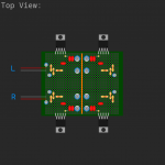
With this design i can fit 4x LM1875 in BTL mode for 2 channels.
Edited:
Forgot to mention the 4 IC's on the same PCB.
Last edited:
Hello.1875, 2030,and 2050 are interchangeable, except for the difference in supply voltage, so you will get thousands of PCB designs on the web.
And in all those years, the kinks would have been ironed out.
And the populated, ready to use boards will cost you only about $ 1.25 here in India, with 'equivalent' 2030...they work well enough at about 18-24 V.
No ties to seller, just a net image to show the item.
I would get a few, test and see, and change out components till satisfied.
Extra in case one gets blown up, shipping is cheaper for a slightly larger shipment, not much difference in shipping cost for one or three boards.
View attachment 1141550
Here 1 board is 1.42 euro not a big difference, but aren't SMD components bad for the sound quality?
"1875, 2030,and 2050 are interchangeable, except for the difference in supply voltage" yes i know.
"but aren't SMD components bad for the sound quality?"
Given the same properties of parts and their inherent parasitics and given the proper part for the proper job has been picked, I would always choose an smd part over a through hole part with regards to "sound quality". For example in your case of working with a TO220 package it is possible to put SMD decoupling capacitors and the feedback R directly onto the pins to minimize parasitics.
Given the same properties of parts and their inherent parasitics and given the proper part for the proper job has been picked, I would always choose an smd part over a through hole part with regards to "sound quality". For example in your case of working with a TO220 package it is possible to put SMD decoupling capacitors and the feedback R directly onto the pins to minimize parasitics.
See an example here of a voltage regulator I built. The 1206 programming resistor fits between the pins. Compact build.
I think you are right, i will give it a shot."but aren't SMD components bad for the sound quality?"
Given the same properties of parts and their inherent parasitics and given the proper part for the proper job has been picked, I would always choose an smd part over a through hole part with regards to "sound quality". For example in your case of working with a TO220 package it is possible to put SMD decoupling capacitors and the feedback R directly onto the pins to minimize parasitics.
Thanks for the info.

- Home
- Amplifiers
- Chip Amps
- LM1875