Hello everyone. I found a Project Phono Box mm/mc phono preamplifier at a garage sale, the model that is powered by an external 16v AC source.
Since I already have an IFI ZEN Phono, I want to experiment with modifying the Project towards the Actidamp II, just to see how it sounds.
I have found the thread of said modification, but when I look at the circuit board I see that as IC it has TL 071 CP.
I have searched for information and I see that this integrated is not dual.
How could they use it as a dual IC? Or is there a dual version of the TL 071?
Since I haven't bought the transformer yet, I haven't been able to test it, I don't know if it's working.
Another question. Is it convenient to spend time in the modification towards the Actidamp?
According to what I have read, it would be the original scheme of the designer.
Greetings.
Attachments
TL072 is a dual 071 but lacks compensation and balance pins. You rarely need them in such a circuit. But your schematic demands single opamps like TL081/071, etc.
Cordial saludo Botija.
Cordial saludo Botija.
How are you Osvaldo? I write in English because I think the forum requires it.
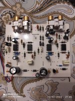
I bought this item very carefully at a neighborhood fair (less than 2 dollars = $uy 70).
I haven't tested if it works, but the circuit has a TL071 and I see that the pin out on one side is connected to the pin in+ on the other side on the same IC through a resistor network and cap, as if it were a TL072 .
Could it be badly assembled from the factory?
In any case, I think I will replace it with NE5532. It would be good?.
Silly questions, don't forget I'm an amateur, not a technician.
Greetings.
All nets I see are between #2 (inverting input) and #6 (out) as in very most single device in a package.
One of them (unit #3) has a null compensation that imo in this job is useless.
I'm engineer and very happy of help you.
One of them (unit #3) has a null compensation that imo in this job is useless.
I'm engineer and very happy of help you.
Last edited:
Do not recommend replacing anything, it is just fine as-is.
Please not not damage the circuit, this is a nice unit. You do not understand how it works.
You can be certain that the factory knows exactly what they are doing.
Please not not damage the circuit, this is a nice unit. You do not understand how it works.
You can be certain that the factory knows exactly what they are doing.
I had found this post. I wanted to do it as stated here. A friend of the designer of the original circuit, Dr. Sykora, intervenes in the subject. Apparently Project took the original circuit and modified it.
https://www.diyaudio.com/community/threads/schematic-for-pro-ject-phono-box.21833/
https://www.diyaudio.com/community/threads/schematic-for-pro-ject-phono-box.21833/

I apologize. As a result of my ignorance I confused the place of the operational amps.
Looking closely at the circuit, the main operational is a LM833 that is dual and the TL071 operates as a DC corrector. It may be so?.
What I have read is that the passive components in the Project would not follow the RIAA correction tightly. That is why they suggest the substitution of some resistors and some capacitor.
I don't know whether to put the TL071 the preset to calibrate the cc to zero.
Sorry. I think the TL071 acts as a DC corrector.
Attachments
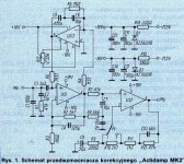
José, in your schematic are depicted three single opamps. All #7 pins are positive supply and all #4 is negative. No double opamps in it. LM833 is dual.
The TL071 and the resistors and capacitors around it both act as a DC servo loop and as an electrically cold input resistor (as the inventors of electrically cold input resistors called it in 1939). Thanks to R5, the signal voltage at the output of US3 at audio frequencies is -28 times the input voltage. As a result, you get an input resistance of R6/(28 + 1), but with less thermal noise than with a normal resistor.
José, in your schematic are depicted three single opamps. All #7 pins are positive supply and all #4 is negative. No double opamps in it. LM833 is dual.
You are correct, of course. The schematic in the pdf file attached to the first post is very similar, but with a dual op-amp and with some drawing errors.
Osvaldo. Sí, en el esquema hay tres operativos. Es el esquema del Actidamp, supuestamente diseñado por Sykora, y que Project tomó para hacer el Project Phono Box mm/mc.José, en tu esquema se representan tres amplificadores operacionales individuales. Todos los pines #7 son suministro positivo y todos los #4 son negativos. No hay opamps dobles en él. LM833 es dual.
El Proyecto es algo diferente, tiene 1 LM833 integrado, que actúa como primera etapa y segunda etapa de la pre.
El tercer IC es un TL071 que creo que es algo para compensar la salida DC.
Attachments
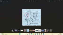
Yeah. I have seen some error compared to Actidamp diagramYou are correct, of course. The schematic in the pdf file attached to the first post is very similar, but with a dual op-amp and with some drawing errors.
R7 is connected to the wrong side of R6 in the pdf. I don't know if there are any other errors, but the way C7 and R9 are connected seems a little peculiar.
Actually, in the PDF they wanted to reverse engineer the Project circuit and they made that mistake.
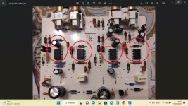
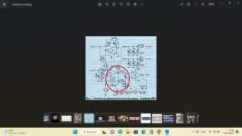
The reality is that the circuit of the Project is similar to that of the Actidamp II as seen in the photo.
There are differences in values of some resistors and capacitors and the other difference is that the IC that operates as a DC servo has a variable resistor between pin 1 and 5 with + centered.
Attachments
- Home
- Source & Line
- Analogue Source
- Question about Project Phono Box