I built this Tangent Pimeta2 over decade ago:
https://tangentsoft.com/audio/pimeta2/
It has worked fine for years, even surviving many daily road trips and errand runs. Sound quality is first rate!
BATTERY POWER, IEMs and CURRENT DRAW :
I have been using an external battery pack comprised of 10 AA 1.25v NiMH batts. So I have about 13-14 v of power for my PIMETA2. The charge lasts about 7 hours (I built a multi-hue battery health LED ckt for the front of the PIMETA2; this provides very good insight about how the PIMETA2 uses batts).
As an experiment , I recently switched to two 9v alkaline in series (18v).
Music played as normal, perhaps a bit more beefy and dynamic given the extra voltage.
HOWEVER...
My PIMETA2 drained two new Ray-o-Vac 9v alkalines in less than two hours. I noticed this symptom rather quickly: music went from sounding ok to very distorted over the span of only, maybe, two minutes. This is when I checked the batt. LED: Indeed, the PIMETA2's batt indicator was almost not visible anymore (it was beyond hue change--- very dim).
I switched the PIMETA2 off for about a min. Turned it on. Same batts inside. All LEDs green again, but same battery-draining thing happened -- only now after perhaps 5 min of use. Seems as if the 9v battery chemistry was beyond recovery!
All these years of uneventful use, I never wondered/guessed how much current the PIMETA2 draws (idle or playing music thru IEMs) until the two 9v alkaline in series incident.
I measured PIMETA2's current draw at batt terminal with my Fluke 87.
Idle (no input or IEMs plugged in): ____ mA.
Music, normal volume, with JVC IEMs: ___ mA.
I assume this ____ mA is draw NORMAL given that I opted for buffers. (I did bias into class A; my L, R and G channel opamps: all AD825). And I also use this completely passive xfeed board. Modified Linkwitz Crossfeed https://tangentsoft.com/audio/mlxfeed.html
I only use IEMs with this and all my portable headphone amps. I have a 2006 Go-Vibe portable amp that uses a single 9v batt. The GoVibe also has an op-amp ground channel. It draws: only 6-7 mA (idle or with music into IEMs)
Try to guess " ___ mA" based on the info provided above, as well as links to the device -- theory of oper., topology, schematics, BOM, etc -- on the original Tangent website.
Reason for asking: believe it or not, the original designer has no clue about his own creations' specs. And he seems to avoid all queries about such topics. The whole PIMETA project was group-forum effort on the orig Headwize site, so Tangent may genuinely be clueless about many specs.
The idle draw is pretty easy to calculate from the schematic. The complete amp contains one AD8610, one AD8620, and three LH6321. Perusing the respective data sheets reveals the total idle draw should be around 2.5 + 2*2.5 + 3*10 = 37.5 mA (typical).
It'll draw more current if you enable the Class A bias for the controlling opamp. I don't know what the bias is supposed to be, but if we assume the trimpot (RBIAS) is set to the midpoint of its travel, you'll have about 1 mA running in each of the three branches of the current mirror. That brings the total idle current draw up to about 40 mA (typical).
Worst case will be higher. You can look those up in the data sheets and do the math.
9 V batteries tend to not have the greatest capacity. A string of Eneloop AA batteries will outlast the 9 V types by a fair margin.
Tom

40 mA is a good, educated guess based on what Tangent suggests for using as opamps.The idle draw is pretty easy to calculate from the schematic. The complete amp contains one AD8610, one AD8620, and three LH6321. Perusing the respective data sheets reveals the total idle draw should be around 2.5 + 2*2.5 + 3*10 = 37.5 mA (typical).
It'll draw more current if you enable the Class A bias for the controlling opamp. I don't know what the bias is supposed to be, but if we assume the trimpot (RBIAS) is set to the midpoint of its travel, you'll have about 1 mA running in each of the three branches of the current mirror. That brings the total idle current draw up to about 40 mA (typical).
Your calculations are quite a bit off from my own metrics, but not by orders of magnitude.
I am not using AD8610, and one AD8620. I orig. noted I'm using AD825 for all except buffers. The buffers are indeed: LH6321
So: 3 * 6.5 + 3 * 10 =49.5mA
Also: Two LEDs (always-on for bias[see schematic], and a third always-on bi-color LED for battery voltage [will turn from green to orange to red as voltage sinks below ~8.4 v]. 12-20 mA for each LED, . Let's keep this number to a reasonable total LED draw: 3*15 = 45
Another thing forgot to mention (apologies -- major oversight) is that the PIMETA2 amp draws current based on how much input power it receives. That is, if I used a 9v, 14v or 18v batt pack, respectively, the current draw also increases respectively : the more I give it, the more it'll take. Not sure about what is causing this????
The sound fidelity on the PIMETA2 is fantastic, with very little noise and hiss. Turns onn/off w/o thumps. Output DC offset voltage (at phones out) is and has been about 1.0 mV dc . And has been that way since I built it over a decade. No re-biasing or component replacement. No electro cap issues (4x 680 uF 50 v Pana FM). No sign of heat damage or corrosion.
So .... what is the total measured current draw of my Pimeta2, using 18v ?
(HINT: the current at idle -- nothing plugged in, input / earphones -- and with music driving IEMs is identical even at moderate volume)
It is time for somebody to invent the Ampere Meter and start including it in multi-meters.
Meanwhile a 1 Ohm resistor and a common DMM can read current.
Meanwhile a 1 Ohm resistor and a common DMM can read current.
I noted my Fluke 87 in the OP.
Anyway ...
Supplied 18v; Draw: 107.00 mA (idle or music @ moderate vol with IEMs)
Supplied 12.5v; Draw: 95.00 mA (idle or music @ moderate vol with IEMs)
Supplied 9.0v ; Draw: 75 mA (idle or music @ moderate vol with IEMs)
Anyway ...
Supplied 18v; Draw: 107.00 mA (idle or music @ moderate vol with IEMs)
Supplied 12.5v; Draw: 95.00 mA (idle or music @ moderate vol with IEMs)
Supplied 9.0v ; Draw: 75 mA (idle or music @ moderate vol with IEMs)
100mA will drain a 9V fast.
Aren't most IEMs like 110dB and 16 Ohms? Seem like many-many times more voltage than you could need.
Aren't most IEMs like 110dB and 16 Ohms? Seem like many-many times more voltage than you could need.
Use an old laptop battery, and put new LEDs, with drop resistors.
They will drain less current, being more efficient.
Old batteries from cell phone will happily run your headphone amp, 4000 to 6000 mAh are common now, and they work nicely, they get dumped because they cannot supply the comparatively high current needed during boot up.
More compact than a lap top battery.
Or simply rig up secondary 18650 cells in series, 4 will give you nearly 15 volts....enough.
Like I noted, the current draw doesn't change when I plug in IEMs and play music at moderate volume.Aren't most IEMs like 110dB and 16 Ohms? Seem like many-many times more voltage than you could need.
That said: The audiophile headphone community is in bit of flux. It seems that clean speaker power may be ideal to drive some cans. Including IEMs.
Wireless / Bluetooth headphones are going for less than $10 here, for use with cell phones. Starting price.
YMMV.
YMMV.
Too much work with new LEDs and drop R's. Many reasons; one being that 2 of the 3 LEDs are specifically chosen for biasing the circuit.Use an old laptop battery, and put new LEDs, with drop resistors.
Or simply rig up secondary 18650 cells in series, 4 will give you nearly 15 volts....enough.
About 18650 cells ... yes, for some time I have been looking at those for amp use, especially in packs for drones and RC.
What I was hinting. This idle power is so huge that the audio does not matter. And any audiophile community can be stirred into a flux.Like I noted, the current draw doesn't change when I plug in IEMs and play music at moderate volume.
I'm looking at this schematic: https://tangentsoft.com/audio/pimeta2/misc/sch-2.01.pdf If you're using a different one you might want to share it.Also: Two LEDs (always-on for bias[see schematic], and a third always-on bi-color LED for battery voltage [will turn from green to orange to red as voltage sinks below ~8.4 v]. 12-20 mA for each LED, . Let's keep this number to a reasonable total LED draw: 3*15 = 45
I only see two LEDs. One indicates ON. The other is used for the current source for the class A biasing.
LED1 runs at (18-3.7)/10 = 1.4 mA.
LED2 runs at (3.7-Vbe)/6 = 0.5 mA to (3.7-Vbe)/1 = 3 mA, depending on the setting of the trimpot, assuming Vbe = 0.7 V which is reasonable for room temperature operation and silicon devices.
So where do the 12-20 mA come from? Running double digit mA in an LED in a battery operated amp is a waste of power.
Tom
Whaaaaaaatt?? 🙂And any audiophile community can be stirred into a flux.
Tom
As we get older, we get resistant to change.
Audiophiles can be extreme about many things, and I found the video quite pretentious.
Audiophile headphones do not come across as a good idea...
Audiophiles can be extreme about many things, and I found the video quite pretentious.
Audiophile headphones do not come across as a good idea...
Tom: Please read my earlier comments; some of those comments contain answers to your queries above.I'm looking at this schematic: https://tangentsoft.com/audio/pimeta2/misc/sch-2.01.pdf If you're using a different one you might want to share it.
I only see two LEDs. One indicates ON. The other is used for the current source for the class A biasing.
LED1 runs at (18-3.7)/10 = 1.4 mA.
LED2 runs at (3.7-Vbe)/6 = 0.5 mA to (3.7-Vbe)/1 = 3 mA, depending on the setting of the trimpot, assuming Vbe = 0.7 V which is reasonable for room temperature operation and silicon devices.
So where do the 12-20 mA come from? Running double digit mA in an LED in a battery operated amp is a waste of power.
Tom
I am not using AD8610, and one AD8620. I orig. noted I'm using AD825 for all except buffers. The buffers are indeed: LH6321
So: 3 * 6.5 + 3 * 10 =49.5mA
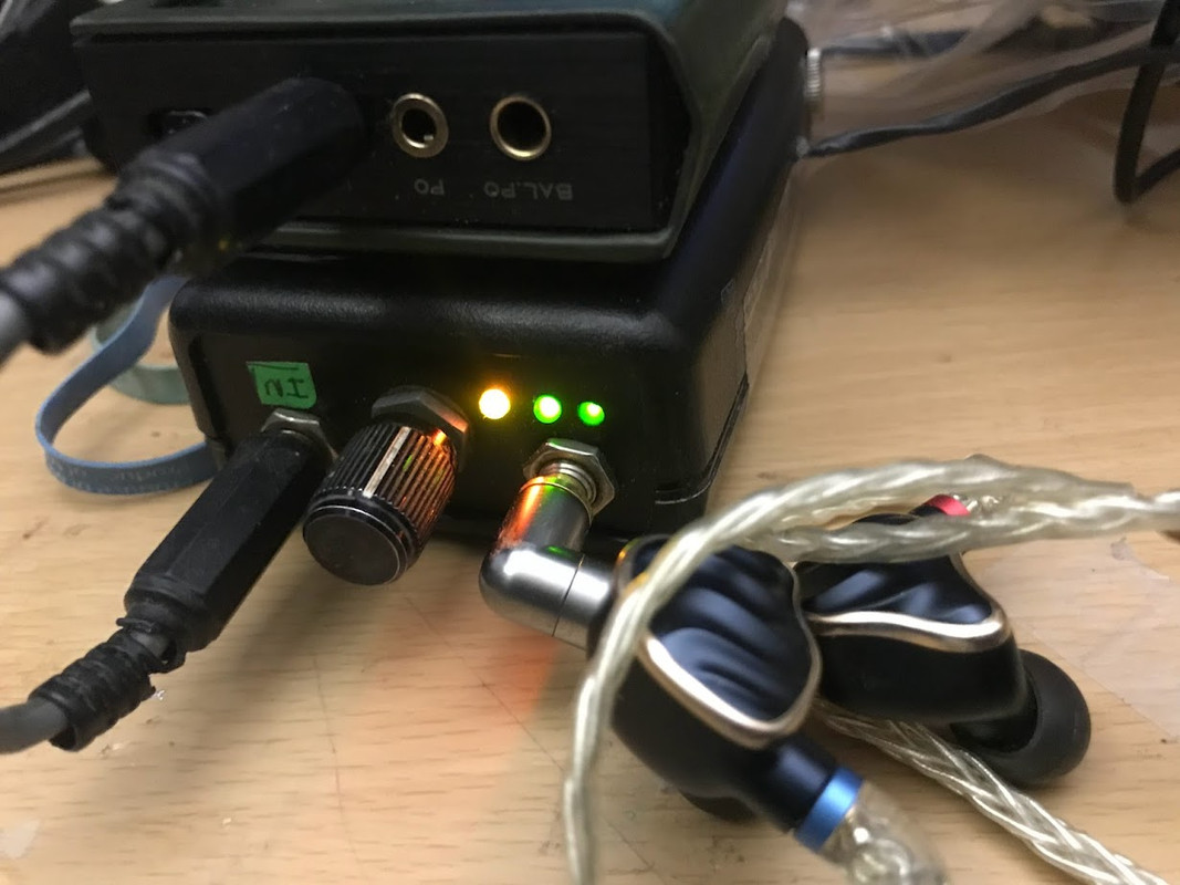
As I noted, Post 3: "and a third always-on tri-color LED for battery voltage [will turn from green to orange to red as voltage sinks below ~8.4 v]."
All three LEDs -- two biasing; one batt. heath -- of my 12-year-old Pimeta2 can be seen in this recent photo:
About ... "where do the 12-20 mA come from?"
Several sources and LED datasheet refer to this range:
https://www.electronics-tutorials.w...n LED's require a,being the most common range.
http://www.learningaboutelectronics.com/Articles/What-is-the-forward-current-of-an-LED
Also, no-one has speculated about my measurements in Post 5.
I don't understand your attitude. I'm actually trying to help you understand where the current goes. Maybe we could work to reduce it. Is that your goal?
Your 49.5 mA is off by the way. You state in your rambling first post that you're using Class A bias, but don't disclose what you have the bias set to. So I guess we're free to guess. As I calculated in Post #12, the Class A bias can be anywhere from 0.5 mA to 3 mA. There're three branches that run at that current, so you need to add 1.5-9 mA to your 49.5 mA. That brings you to 51-58.5 mA. Still well below the 100 mA you measure.
As I mentioned in Post #12, we could provide better help for you if you posted a schematic of the circuit you're using. You might even be able to learn a thing or two. But maybe you're not into receiving help. Or learning. Your call!
Tom
That's great. But what is the current draw of the LEDs in YOUR circuit? Low-current LEDs do exist, ya know. Some will glow brightly on 1 mA.Several sources and LED datasheet refer to this range
Unfortunately that says nothing about the current draw except that it's greater than 0 mA.But the two biasing LEDs do glow moderately bright.
What's there to speculate about? The circuit draws a lot of current. More than is expected from your calculation of 49.5 mA.Also, no-one has speculated about my measurements in Post 5.
Your 49.5 mA is off by the way. You state in your rambling first post that you're using Class A bias, but don't disclose what you have the bias set to. So I guess we're free to guess. As I calculated in Post #12, the Class A bias can be anywhere from 0.5 mA to 3 mA. There're three branches that run at that current, so you need to add 1.5-9 mA to your 49.5 mA. That brings you to 51-58.5 mA. Still well below the 100 mA you measure.
As I mentioned in Post #12, we could provide better help for you if you posted a schematic of the circuit you're using. You might even be able to learn a thing or two. But maybe you're not into receiving help. Or learning. Your call!
Tom
The schematic is the same as that on the Tangent site you linked earlier. As I've noted several times in this thread," I am not using AD8610, and one AD8620 [suggested in the schema]. I orig. noted I'm using AD825 for all except buffers. The buffers are indeed: LH6321"As I mentioned in Post #12, we could provide better help for you if you posted a schematic of the circuit you're using.
Also, that tri-color LED battery health circuit was an add-on. Not sure where I found that ckt, but it's on small veroboard inside the case, just behind front panel.
About class-A bias ... not sure ... I went thru the calibration procedure on the Tangent site:
https://tangentsoft.com/audio/pimeta2/tweaks.html#class-a
But as Tangent notes and as you speculate, the biasing current is quite trivial to my "mystery".
Again, the bottom line question is why this:
Supplied 18v; Draw: 107.00 mA (idle or music @ moderate vol with IEMs)
Supplied 12.5v; Draw: 95.00 mA (idle or music @ moderate vol with IEMs)
Supplied 9.0v ; Draw: 75 mA (idle or music @ moderate vol with IEMs)
Incidentally --- the high current draw might not be problem or flaw, per se. Just an unsolved mystery, until proper analysis can be outlined. As I noted, it has been this way for over a dozen years. Sonics and reliabilty are first-rate. I have heard many diy and commercial designs, and the Pimeta2 outperforms many of them. (I also have a Tangent PPA-2 running daily, also for about 12 years -- the Pimeta topology is based somewhat on the PPA).
It clearly isn't. You added the battery monitor circuit. Perhaps you could measure the current draw of that circuit. That's likely where the excess current is flowing. Alternatively, disconnect the battery monitor and measure the current draw at idle.The schematic is the same as that on the Tangent site you linked earlier.
The "calibration" basically says "adjust to taste". Either way, as you point out, 1.5-9 mA in the Class A bias circuit is a drop in the bucket compared to the 50-60 mA that we're trying to find.About class-A bias ... not sure ... I went thru the calibration procedure on the Tangent site:
I agree to an extent. If you're happy with the circuit as-is life is grand. If you'd like your batteries to last twice as long it would be worthwhile to track down where the excess current goes so we can fix it. Or you could approach this as a learning exercise. All are valid approaches. However, without a schematic of the full circuit, i.e., everything that's connected to the battery a proper analysis is impossible.Incidentally --- the high current draw might not be problem or flaw, per se. Just an unsolved mystery, until proper analysis can be outlined.
Tom
About the tri-color LED battery health circuit.... it's based on the LM358 opamp. I diy'd something I found on the web over a dozen years ago.
78.4 mA (batt health in situ)
74.5 mA (batt health ckt disconnected)
Increasing to 12.4 v, my Pimeta2 draws:
94.1 mA (batt health in situ)
Circuit analysis is tricky stuff. Not as simple as Kirchhoff or Matrix Linear Algebra or even SPICE simulations. A lot of synergistic things going along that are difficult to isolate.
In the meantime, lets call this dreamy Pimeta "possessed".
Photos of interior of my Pimeta2 with diy batt-health ckt. And other interior photos.
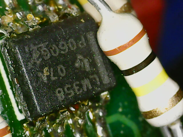
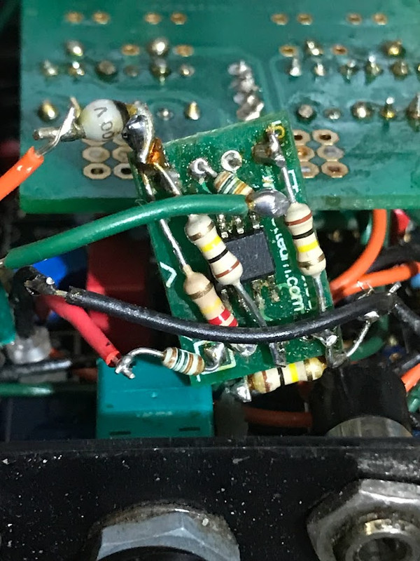
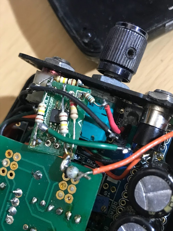
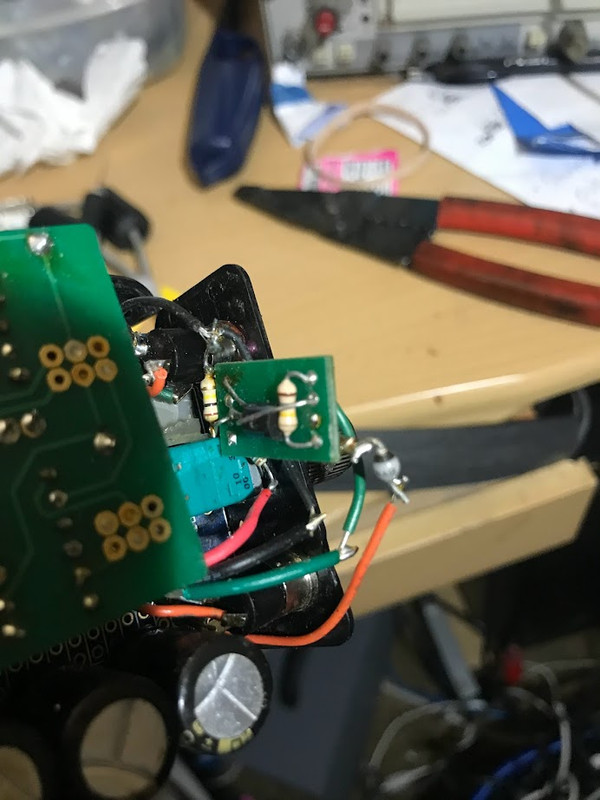
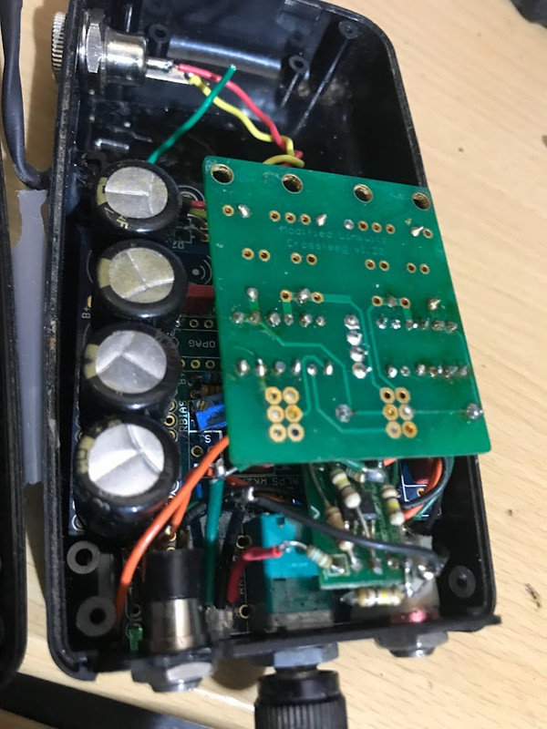
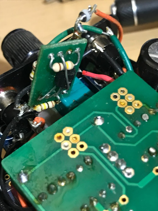
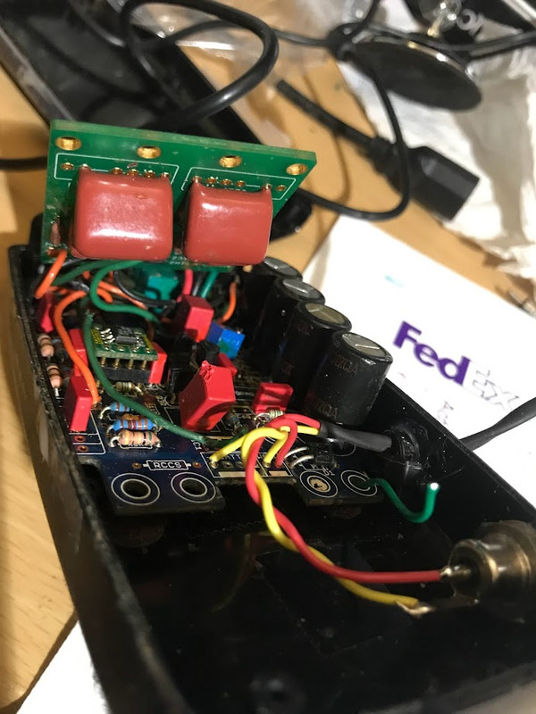
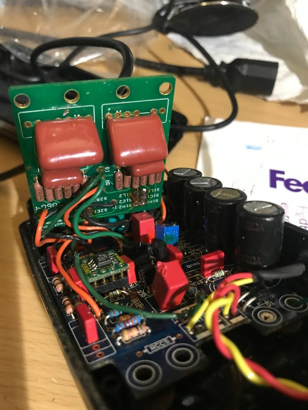
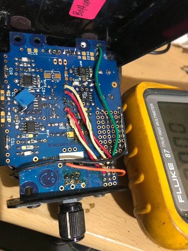
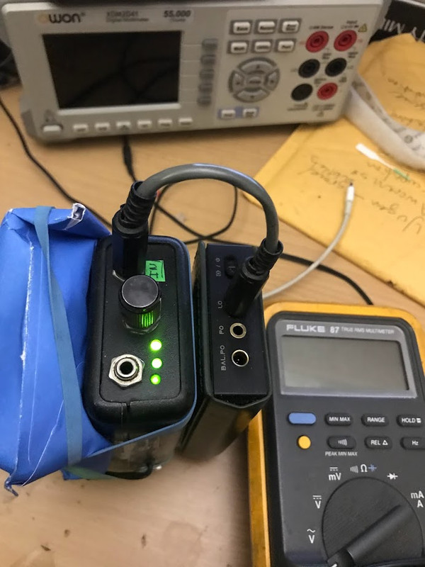
Photo (below) of exterior of my Pimeta2, with batt-health LED in "amber mode" (below 8.4 but above 7.5 v, I think).
Using a somewhat depleted "9v" Ray-o-Vac (no-load voltage: 7.97 v) my Pimeta2 draws:tomchr: Perhaps you could measure the current draw of that circuit. That's likely where the excess current is flowing. Alternatively, disconnect the battery monitor and measure the current draw at idle.
78.4 mA (batt health in situ)
74.5 mA (batt health ckt disconnected)
Increasing to 12.4 v, my Pimeta2 draws:
94.1 mA (batt health in situ)
Circuit analysis is tricky stuff. Not as simple as Kirchhoff or Matrix Linear Algebra or even SPICE simulations. A lot of synergistic things going along that are difficult to isolate.
In the meantime, lets call this dreamy Pimeta "possessed".
Photos of interior of my Pimeta2 with diy batt-health ckt. And other interior photos.
Photo (below) of exterior of my Pimeta2, with batt-health LED in "amber mode" (below 8.4 but above 7.5 v, I think).
Last edited:
- Home
- Amplifiers
- Headphone Systems
- Guess current draw for a portable headphone amp?