This amp has no output.There is no rail to rail oscillation on the output FETs.I see a square wave on the output of the Lm211 and pin one of the IRS chip.
Using the ground tap of the 7812 regulator vcc voltage looks ok for the chip.I install a new on but no change.
Any suggestions?
Using the ground tap of the 7812 regulator vcc voltage looks ok for the chip.I install a new on but no change.
Any suggestions?
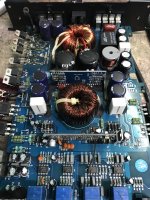
Attachments
That's too low. Check the mute/delay transistor that drives that terminal. It's generally marked 1302.
Transistor connected to that pin has MAX marking on it.I pull one from a donor board and replace it .Voltage is still low.On the other pins of that transistor I don’t see no voltage.
That's for the over-current protection. It's driven by the LM293 on the driver board. There should be a transistor that drives pin 2 of the 21844 on the main board (driving the SD pin on the header).
If you talking about the TO92 transistor that the larger amps have close to the drive board there is none in this amp.
There is nothing to drive the SD pin of the 21844 high. It's pulled high internally.
Are there any outputs in the amp as of now?
What connects (on the main board) to the SD terminal of the header on the driver board?
Are there any outputs in the amp as of now?
What connects (on the main board) to the SD terminal of the header on the driver board?
All outputs installed.
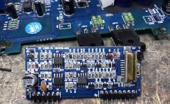
Pin 2 is not directly connected to any pin on the header.It’s directly connected to the points I mark red. D2 L2 and Q6 which is the max transistor .
Pin 2 is not directly connected to any pin on the header.It’s directly connected to the points I mark red. D2 L2 and Q6 which is the max transistor .
It's sometimes risky to power up without the startup delay but you need to lift terminal 2 of the 21844 to see if it goes up to about 5v without being connected to the pad.
I did not lift pin 2 because this was my last 21844 but I cut a trace and lift the inductor ,Now I see 3.8v on pin 2 and now there is rail to rail oscillation on the outputs.
With everything connected and the max out no oscillation .With D2 out there is oscillation .The other end of D2 is directly connected to Q1 mark BR.If I remove Q1 there is oscillation .Q1 test good out of circuit .
With the black probe on the emitter of Q1, what's the DC voltage on the other two terminals of Q1?
- Home
- General Interest
- Car Audio
- Crunch class D