Hi Guys,
Im doing my first build of a Hiraga 30 Watt class a . I put all components right and checked them all, but appearently my powerstage does not go 1,5 amps current.
I did some measurements, maybe you can give me some direction where to look / what might be wrong?
There is no load, input shortend, and it does amplifie, all be it crooked class B with a lot of distortion. Im puzzled !
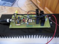
Are the transistors in the final stage (2sc5200 and 2sa1943) properly mounted?
I.e. fully isolated from heatsink using proper mica and (less) goop. Photo appears showing round mica?
Please perform continuity check from collector (middle pin) to bare metal on heatsink.
If there is a short, than that's the problem. While you are at it, measure the drivers as well.
Hope this helps
Tnx, rion, Ill check those triple time. (just did, no shorts) It looks a bit messy indeed, its my first build in 30 years. Im a bit worried about the currents in the separate driver stages. first driver stage: 0.08V on 180 R thats only 0.4 mA ? Second stage , 0.61 V on 1K , thats only 0.6mA to drive the 634 and 1096. ?
And why the 5.3V on the 5200 BE ?
And why the 5.3V on the 5200 BE ?
Last edited:
If there is 5.3Vdc on the 5200 Vbe, the amp (feedbackloop) is trying to correct the output to the desired stable setpoint. But it can't manage to do so!. 14/15mV over the E33 resistors yields 42/45mA through the drivers,so the 5200/1943 combo are closed.
Check pinning, continuity, wiring, solderings &c. It's not about shortings.
What dc voltages on both sides of the 300R feedback resistor?
(You did not swap/mirrored accidentally the 5200/1943 on the pcb???)
Check pinning, continuity, wiring, solderings &c. It's not about shortings.
What dc voltages on both sides of the 300R feedback resistor?
(You did not swap/mirrored accidentally the 5200/1943 on the pcb???)
@Smaragdkade
For the super Class A 30W, I had the same problem. I lowered the values of the bias resistors from 47K to 27K (original Hiraga has 33K) and now the amp sounds divine.
I get ~1.4A class A bias.
For the super Class A 30W, I had the same problem. I lowered the values of the bias resistors from 47K to 27K (original Hiraga has 33K) and now the amp sounds divine.
I get ~1.4A class A bias.
Last edited:
Exactly! Here is my build:Mounting the drivers on the same heatsink as the 5200/1943 is not a good idea: thermal run off!
Have the drivers on separate heatsinks whatsoever!
Attachments

Tnx guys, good suggestions thanks ! Getting the drivers off the cooling is a good one. Will do that. Furthermore, what antoine said, the 47K had to be lowered. I have them now at 33K and the amp stabelise @ 900mA/35V. (40 C ) But !!!!! I am now running into a new (sortof) problem..

I have mounted the pcb vertical, so the lower output transister is better cooled than the upper.... its 5 degrees C difference. And that means drift/offset....
I have mounted the pcb vertical, so the lower output transister is better cooled than the upper.... its 5 degrees C difference. And that means drift/offset....
Last edited:
sure, you are right. electricaly its ok, but it looks awefull.....but this is my first prototype.....there will be a version 2, wich will look much more neat.Its probably not going to help much, but I'm very suspicious regarding the power transistor mounting.
And maybe a bit too many bare wires in the power supply (not explaining your issue).
Last edited:
The heatsinks i used are from two deceased audioanalyse amps....i stacked themfor now , but thermally they are not snug connected. I might reconsider the whole setup, side by side instead of stacked. hmm...maybe a square amp with a heatsink on all four sides....
Attachments
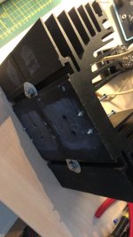
I just talked to my son. He's 21 and he works at a metalworking company. He's very good in cutting cnc and stuff. Soo tomorrow he will cut 2 pieces of 5 or 6mm thick aluminum to thermally connect both heatsinks. see picture. This makes it possible to mount both transistors horizontal and thermally equal. Have to move the pcb's from vertical to horizontal, but that doesnt seem to be a problem. Bonus is that those ugly 8mm bolts go away ;-)

Last edited:
Oh, i just did a full sweep 0-->200 khz (no load) but all seems fine on my scope for now. -3db roll off is at 180 khz. Horizontally mounted and @ 800mA current the heatsink stay mildly warm, tomorrow ill try 27K instead of 33k resistors for the drivers to get a +1A current on the sc5200 etc.
Last edited:
Well done pcb setup, reliable and condensed.Exactly! Here is my build:
Sziklai's should be separated thermally unconditionally always whatsoever. It's the very only restriction for these compound configurations.
some progress, changed the setup. Put both drivers on their own cooling element. Joined both endstage coolings with thermal epoxy. Maybe not 100% conductive but I'll give it a shot. Tomorrow the wiring and testing. The layout of this print is a little tiny for all components. Also i put all the components a couple of mm from the board for easy acces of my measuring pins. Als changed the 1W resistors from 47K to 27K to get +1 amp current through the endstage. Thast will be a 60+ watts of heat !


Last edited:
- Home
- Amplifiers
- Solid State
- Hiraga 30Watt build… can't get it right (help!)