changed the 27k driver resistors back to 33K/1W , after a half an hour the amp settles @ 0,82A @32V , output 10mv DC (+/-), it wobbles a bit up and down, but so does my mains. Temp @ 2SC5200 = 44C
Last edited:
I have the second half of the amp running now, looks stable . But while checking the signal path with my scope i noticed this. on the base of the output transistors and ouput itself.

Time is 10ms so 100Hz, Vpp is 80mV. My supply has a 100Hz 300mVpp ripple @ 32V while running 900mA current through SC5200, which doesnt seem too bad i guess? (no load/input shorted) . Is this something to worry about ?

Time is 10ms so 100Hz, Vpp is 80mV. My supply has a 100Hz 300mVpp ripple @ 32V while running 900mA current through SC5200, which doesnt seem too bad i guess? (no load/input shorted) . Is this something to worry about ?
Last edited:
My best guess is that you can see the charging spikes from the supply rails: first a small dip when the rectifier diodes starts to charge the supply caps, and after 2msec the caps are full and the bridge closes. A spike from inductors (?) feeds the caps a little bit more.
Is the supply CLC or CRC smoothed? Hiraga used CRC. There is a simple but very smart supply application on the web (other members here have the link ready... I haven't, sorry) to determine if the supply setup is susceptible for this ringing.
Can you post a circuit diagram of your supply?
Is the supply CLC or CRC smoothed? Hiraga used CRC. There is a simple but very smart supply application on the web (other members here have the link ready... I haven't, sorry) to determine if the supply setup is susceptible for this ringing.
Can you post a circuit diagram of your supply?
Addition:
These spikes (dips) are injected into the signal path through R19/R20 easely.
Q3/Q4 are close to the rails surrounded by (relative, current speaking) low value resistors, so I don't expect susceptibility there.
Curious to observe these alternating spikes actually while typing this. It should be mirrored on the circled nodes. Hmmm...
Sounds plausible. My supply now is plain C 3*10.000uF, so per channel 60.000uF + 2uF foil per rail. No R or L yet. Per channel 2 bridge rectifiers.
Last edited:
I would recommend the original C-R-C//C setup here, so a split between the first 10mF cap and the last two 10mF caps with a high power resistor in between. What value did Hirage use again?
There is some serious inductance in the transformer also.
There is some serious inductance in the transformer also.
4 to 8 Ω / 10W
original (en) publications attached (if allowed, not sure)
it's with distance my most favourite design
and I own a little monster!
original (en) publications attached (if allowed, not sure)
it's with distance my most favourite design
and I own a little monster!
Attachments

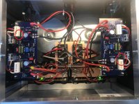
Put both halves on the main chassis, a lot of wiring to do , an do it neatly also. Quite a challenge ;-)
Also, both outputs keep drifting up and down, +/- 100 mV . It might not damage any speaker but it doesnt feel ok.
So i tried to figure out where this drift comes from. Its the driver transistors. The are not thermally coupled. If i blow just a little bit, on one of the drivers the output swings to a 250 mV DC. If I put the lid on the housing drift stays within 20mV DC.
Last edited:
Both drivers run some 28mA (from R19/R20 + 0.82A/ß = 8mA) times 36Vdc supply voltage sums 1W which should be ok with given bipolars and heatsinks. The 1943/5200 part adds/draws 8mA, so rather a significant value (28%).
Knowing that the Sziklai is a thermal challenge, larger heatsinks for the A634/C1096 are an option here to prevent 'blowdrift'.
Knowing that the Sziklai is a thermal challenge, larger heatsinks for the A634/C1096 are an option here to prevent 'blowdrift'.
You are right, current heatsinks are a tad tooo small, 60C . For now ok, this is just my first proto. If this monstre sounds as good as my 6L6 SE than there will be a next version ;
Bigger housing (more room for Capacitors)
Different print layout / component placing
With the complete assembled housing drift is within 10mV.


Lets see if we can beat this one ;-)
Bigger housing (more room for Capacitors)
Different print layout / component placing
With the complete assembled housing drift is within 10mV.
Lets see if we can beat this one ;-)
Expand the drivers heat sinks - the final amp looks good (superb symmetric) and 10mV is way closer then my little monster (on planars).
Do you sell?
Do you sell?
Where is the point I circled in red located? I mean the exact physical location inside the amplifier build. I am asking this because sometimes the spikes you have shown in post #22 could be corrected by choosing the feedback signal pickup point as close as possible to the actual binding posts... which in this case could work really well due to the non-existent Zobel filter. I learnt this many decades ago when I was playing with Japanese amplifiers.
I suppose you could give it a go and see what happens with those spikes..?
Another approach is what was already mentioned above... tackle the root cause by reducing the PS ripple and possibly by using fast-switching soft recovery diodes.

I suppose you could give it a go and see what happens with those spikes..?
Another approach is what was already mentioned above... tackle the root cause by reducing the PS ripple and possibly by using fast-switching soft recovery diodes.
Beautiful. It looks like a flat four! Put a fan and carbs on it and you’ll be burnin’ rubber out the back of an air cooled VW!
Attachments
That point is on the PCB's, see picture . Can you explain what you exactly mean with binding posts ?Where is the point I circled in red located? I mean the exact physical location inside the amplifier build. I am asking this because sometimes the spikes you have shown in post #22 could be corrected by choosing the feedback signal pickup point as close as possible to the actual binding posts... which in this case could work really well due to the non-existent Zobel filter. I learnt this many decades ago when I was playing with Japanese amplifiers.
I suppose you could give it a go and see what happens with those spikes..?
Another approach is what was already mentioned above... tackle the root cause by reducing the PS ripple and possibly by using fast-switching soft recovery diodes.
View attachment 1135671
Attachments
First impression ! Overall better than my 6L6 SE ! Good soundstage vertical/horizontal, goed placing. Slightly more detailing. But most amazing is dynamics. I mean the difference between the less loudest and most loudest sounds is MUCH bigger than my 6L6 SE amp. (maybe something like subjective loudness?). if i put my ear close to the speakers i can hear the ringing though, no hum, so there some work left. Happy camper!. I have no special audio components used so i guess it can only get better from here. (and im gonna call my brother, i want my LS3/5A's back 🙂 )

setup = Modified Philips CD380/disabled oversampling /6N1 output/volume pot , speakers are oldies KEF reference 01 with new crossover components. Cables all audioquest.
setup = Modified Philips CD380/disabled oversampling /6N1 output/volume pot , speakers are oldies KEF reference 01 with new crossover components. Cables all audioquest.
Last edited:
Placed (16 total) 47nF capacitors on the rectifier diodes. Ringing on power rails and output is almost gone. Still some 5mV PS hum....will put a 4Ohm resistor to make a CRCC supply. Also, after running in the whole weekend the endstage current increased from 859mA to 1.1A....on both left and right. Still running in I guess !

Last edited:
et voila ! 2 Ohm/5W CRCC , hum is practically gone. 1 mV max. Now only thing to do is better cooling for the drivers and put a mains filter in.

Last edited:
- Home
- Amplifiers
- Solid State
- Hiraga 30Watt build… can't get it right (help!)