There is a legend that exists among a small circle of people who lived in Sydney in the 1970s. The legend of the Magic Amplifier. The story begins ...
Most of you have heard of Allen Wright (1947-2011) whose final company,
VacuumState Electronics, is still being run in Switzerland by his ex-wife. In the early days Allen gained a reputation for the most amazing AM radio design anyone had ever heard, which was important at the time since Australia hadn't yet gone FM. He once told me that if I ever saw one (only about 200 were ever built) that I should snap it up immediately. I did actually see one for sale about 12 months ago, but let it go - I have done SDR since then and nothing beats SDR. Besides, it would have the wrong whistle filter, we changed to 9 kHz spacing years ago.
Allen was obsessive about finding the best designs possible, and would spend long listening sessions with each audio product he repaired or built. But since there was very little money in audio gear he also worked in other areas to make a living. His company Haltronics made digital test instruments. He also contracted to the Snooper Company in Castlereagh Street to repair radar detectors for cars, and a second contract had us set up a company in Drummoyne to build 1000 video games from kits supplied from the USA. I was his stand-in whenever he needed to go overseas, which happened twice. I also got very good at playing video pong.
🙂
It is a little-known fact that in the early days Allen didn't design his own amplifiers. In fact the shop in Wentworth Avenue was dedicated mostly to modifications of name brands, and Allen gained a solid repuatation as someone who could repair or improve almost anything. He also had a listening room with stacked Quad panels with a (then fashionable) live-end/dead-end setup. But most of the stuff that came through, the bread-and-butter work, was instrument and PA amplifiers. Old valve stuff, with brands like Playmaster and Orange and Phase Linear.
Anyhow, I digress. His book "The Tube Preamp Cookbook" mentions a character called "The Guru" who is a shady, ethereal character living just out of the limelight. In truth Rowan McCombe was even stranger than that. He lived in a Darlinghurst terrace house which was the home of Ellis D. Fogg, well known stage lighting guy who was a family name around the inner city area. You have to remember this was the mid/late 70's, the era of weekly bands touring from overseas and there was a huge demand for his services, as there was for Allen's amplifier repair services. Another close friend of mine, ABC journalist Peter M - who I've known since he was a photographer with ANU travel in 1972 - also lived at the house in Darlinghurst with The Guru, but he was often overseas on assignment.
So there was the little clique of people I knew from different places who had all somehow managed to also know each other. In fact it got so weird that one day that I rang Allen and Peter answered. I asked why he was at Allen's place and he replied that he wasn't, but that he had also dialed Allen and we had gotten a crossed line!
So anyhow, The Guru is the focus of this tale because he had designed the Magic Amp. It was the unkillable reference source, the standard by which all proposed designs and all equipment manufactured by other companies was to be judged, and judged harshly. There was only one Magic Amplifier, and it looked like a rats' nest, but it was allegedly amazing. I never heard that prototype but I know three people who did and they concur that it was unbeatable; or at least it was until one day Allen made a modified tube amp that finally knocked it off the pedestal, as is inevitable with standards.
But before that sad day, Allen was in the process of commercializing the design, and he laid out a PCB to make several copies to ensure that they matched the original. The Cookbook goes into an interesting story about how he messed up the first one, and how The Guru had roasted his @ss about it. But the time between these prototypes being built and the tube amp mod knocking the Magic Amp off its pedestal was very short, and it never went into production.
So, there were three Magic Amps in all; the hand-wired original, the one Allen made for himself and the one that Peter M got. Of the three in existence, Rowan's original probably went to the tip when he passed away, Hanni probably still has Allen's original in Schuffhausen, and Peter M has been promising to send me his copy for years so I can reverse engineer it. The trouble is, he lives on a tiny island off the coast of New Zealand and the amp is in a box somewhere under his son's house in Sydney. Not to mention Covid19.
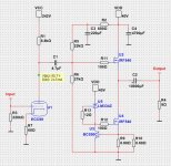
So, when I finally twigged that the circuit on page 8 of the Cookbook was the exact same design a couple of days ago, I became very excited indeed. In fact, I immediately simulated it in Spice and it's good enough that I will be building a replica. Because CURIOSITY, that why. This is the amp of legends, and legends have to be either killed off or made to live on in glorious perpetuity.
Watch this space.

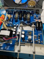

![20230114_084145[1].jpg](https://www.diyaudio.com/community/data/attachments/1038/1038321-d78bdd37d46beed69eab5234deb0242e.jpg?hash=14vdN9Rr7t "20230114_084145[1].jpg")
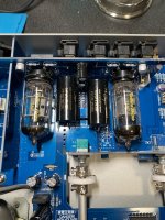
![20230114_093311[1].jpg](https://www.diyaudio.com/community/data/attachments/1038/1038322-00370b0a6b9d2a3c9e6210f7087424fe.jpg?hash=ADcLCmudKj "20230114_093311[1].jpg")
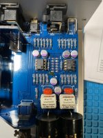
![20230114_195325[1].jpg](https://www.diyaudio.com/community/data/attachments/1038/1038326-106ec87ea5c0195b235e1d3fdc61cedc.jpg?hash=EG7IfqXAGV "20230114_195325[1].jpg")
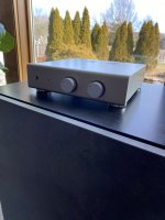
![20230114_195345[1].jpg](https://www.diyaudio.com/community/data/attachments/1038/1038327-6079bbca6b31d2b5bbe4bc7cbc37c442.jpg?hash=YHm7ymsx0r "20230114_195345[1].jpg")
![20230114_083808[1].jpg](https://www.diyaudio.com/community/data/attachments/1038/1038329-dcf00787803f6b6a8fe417d679851094.jpg?hash=3PAHh4A_a2 "20230114_083808[1].jpg")


