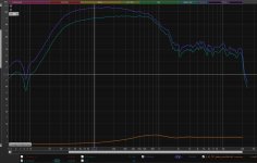
Hi, please I'm completely confused with REW (5.20.13) basic A*B operation result. I'm trying to multiply my response (nierfiled + port) with bafflestep response (generated by Diffraction & Boundary Simulator 1.30 aka DBS). All each freq. responses seem to be ok, as well as DBS .FRD output - see attached pic. But when I make A*B - (NF+port) * BF.frd the result is strange. It's not possible to have more then -6dB difference in final response, but there is more, about -8dB@100Hz. What's wrong here ? It seems, there is an 3dB offset - very suspicious number, isn't it ? 😉
Thanks a lot.
Edit. For ex. here is using the same method to join responses.

Thanks a lot.
Edit. For ex. here is using the same method to join responses.

Last edited:
It depends on the offsets of the individual plots. I'd go ahead and take that 3dB away and see if it looks right.
Member
Joined 2003
You can see in the response >2kHz where you should see near 0 difference, you have about 3dB difference. Check offset values used. Problem likely in step 4 of the linked instructions if that's what you're trying to follow. Quick fix would be just to adjust the amplitude to overlap original response at 10kHz, however it may be useful to determine where you went wrong in your steps.
The link is a rather silly instruction FWIW, overly complicating what could be a simple process, splitting work between REW, Jeff B's old diffraction spreadsheet, then eventually bring into VituixCAD. All tools required are in VituixCAD and will result in a much easier process. As well, the brick wall window (tukey 0.1) shown is step 3 will result in a fair bit of overshoot on the low end of the far field response as well.
The link is a rather silly instruction FWIW, overly complicating what could be a simple process, splitting work between REW, Jeff B's old diffraction spreadsheet, then eventually bring into VituixCAD. All tools required are in VituixCAD and will result in a much easier process. As well, the brick wall window (tukey 0.1) shown is step 3 will result in a fair bit of overshoot on the low end of the far field response as well.
Last edited:
I don't know anymore what to do for that kind of posts. Feedback is ignored and too complex and partly wrong instructions continue forever as sticky threads. REW is needed for measurements and exporting time-windowed far field and near field frequency responses. VituixCAD has Diffraction, Merger and main program which can do the rest in every case. So the process has six phases:The link is a rather silly instruction FWIW, overly complicating what could be a simple process, splitting work between REW, Jeff B's old diffraction spreadsheet, then eventually bring into VituixCAD. All tools required are in VituixCAD and will result in a much easier process.
1) Measure far field IRs in hor and ver planes with REW
2) Time window and export far field FRDs
3) Measure near field IRs
4) Export near field FRDs
5) Simulate and export baffle effect response with VCAD Diffraction
6) Load all FRDs to VCAD Merger, set parameters and Save with Feed speaker checked.
5) Simulate and export baffle effect response with VCAD Diffraction
Sorry for the confusion, but I thought the baffle effect is included in the measurements?
Member
Joined 2003
Okay so this is only for the nearfield response below say 3-400hz, and only applicable if the baffle is large enough to support frequencies in the nearfield range?
Member
Joined 2003
Applicable for all baffles for neafield measurement, standard procedure for merging nearfield and far field responses. It's what the merge tool in VituixCAD is for in step 6.
Nerfield measurement provides half space (4pi) measurement data, up to the frequency limitations of the driver size. See auxillary -> near field section of VituixCAD for some specifics on neafield frequency limitations.
Nerfield measurement provides half space (4pi) measurement data, up to the frequency limitations of the driver size. See auxillary -> near field section of VituixCAD for some specifics on neafield frequency limitations.
Thank you Dcibel, I was not aware of that tool. Very nice!
Is max nearfield frequency where baffle step starts to have an effect?
Is max nearfield frequency where baffle step starts to have an effect?
Member
Joined 2003
Member
Joined 2003
- Home
- Design & Build
- Software Tools
- REW a*b offset issue ?