Source for a good Tripath 2020 amp board

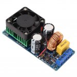
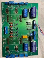
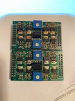
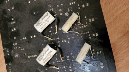
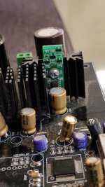
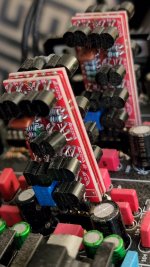
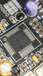
Can anyone suggest a good source for a good Tripath 2020 amplifier board ?
I went to the diyparadise.com site and tried to contact them about the Charlize 2 board .
I was unsuccessful in trying to create a user account there .
Their web page showed their captcha icon as not working and my Safari browser showed the term "unsecured web site" in red in the top pane.
Maybe they are closed down ?
I own a Topping MK2 amp that works and sounds great with my Seas very efficient full range speakers...... but all it's connectors are crammed right next to each other on the rear panel .
I want to make my own 2020 amp with a better layout in a slightly larger chassis with a fused power inlet, larger PS jack and better potentiometer.
I am downsizing from a large and very excellent tube amp for a number of reasons .
Small grandchildren around ; excess amp heat ; Wife wanting to dust the tubes while they're operating (( ::< O ....etc.
Any tips appreciated.
I also have a Dayton DTA 2050 amp but input connectors loose and has hiss galore . A SMSL 3118 with less hiss but fatiguing treble . The 2020 sounds best and NO HISS.

thanks
Modifying an Adcom GFP 555 then adding a DSP, am I insane?

First real post here so please be gentle.

Background is I been ruminating for 6 months or so on building a budget Frankenstein rack-mounted vinyl system out of components I mostly already have. I picked up a couple of decent commercial amps from a store that was upgrading and was thinking of using a pair to separately power some full range speakers and subs using a mini-dsp as a crossover.

I realize i need a phono-stage for riaa and signal gain from the turntable, I'd also like a volume control and an input selector. I dug out Adcom gfp 555 i got some years ago thinking I'd find some cheap Adcom gfa 555s some day, it never happened.
Now I think this is a well regarded pre-amp and in particular the phono stage and I've read a few threads about recapping, rebuilding the PS and opamp swapping which I think is all within my capabilities. It's also rack-mountable so fits with what I'm trying to do. However, there's a lot of extraneous stuff on the amp that i don't need and am thinking of stripping out.
I'd like to remove the headphone amp, bypass all tone/mono/filter controls and remove relevant control knobs and buttons, remove the recording selector and possibly the switched and unswitched ac outlets. All I want and need is the phono stage, preamp, selector and volume.
Is this a crazy idea? To me it seems a doable project and a cost effective way to achieve my goal.

Secondly, I was going to use the mini-dsp 2x4 hd kit and put it in a rackmount enclosure but the enclosure costs just as much as the kit and seems to be overkill for a 4"x5" pcb. I have the idea to mount the dsp inside my pre-amp, routing the connections to the relevant inputs and outputs internally and reconfiguring the rca outputs at the rear of the amp. Possibly powering from the adcom PS. Maybe.
https://www.minidsp.com/products/minidspkits/minidsp-2x4-hd-kit-detail

Am I in danger of men in white coats throwing a butterfly net over me?
Should i waste anymore time thinking about any of the above?

Source for FRD and ZMA files?

Hi;
Does anyone know a good source for .FRD and .ZMA files for drivers (to use in f4ier's Crossover simulation program)?
I know some would say - just measure your own - I will do that once purchased but I would like to do some initial sizings to get in the ballpark before purchasing drivers.
There were several threads out there from people who were starting pages for catalogs of such files, but several were dead links and one was in french.
Any good sources?
Thanks
Topping TP60 schematic?

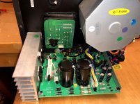
Does anyone have a schematic of the TP60, v15.2? It would make troubleshooting easier for me.

My TP60 suddenly quit on me a week ago. It went off while I was listening, a little slowly (like turning the volume down quickly) as if the power had died rather than suddenly as if the amp chip had just quit. The power light was still on though, and the output relay clicked as expected when powered off/on.

Oddly, when I turned it back on to investigate today, the right channel worked but not the left. I'm sure both went dead when it first died. I've tried the obvious things like swapping the speakers and inputs around and trying the other inputs.

Shame I sold most of my electronics kit a year ago; all I have left now is a couple of good multimeters.


Edit: Typical... I spent 20 minutes searching before I asked, and I just found one now. V11, but it's probably close enough.

Dayton DC-250 and TB W4-1337SDF for a 3 ways

Hi,

my old HT system died after 18 years, it was used as a 2.1 system with 2 (almost) subs built with a Dayton DC-250.
They worked very well as subs with plenty of bass so I never had the need to replace them with a "real" sub speaker.
I would like to build a 2 ways loudspeaker to "join" with the 2 existing subs.
Since I'm not interested to build an HT system, I bought a Yamaha A-S301 that is equipped with a subwoofer pre-out (active low pass at 90 Hz).
So...the 2 DC-250 will be driven by an amp that I built some years ago (a project of Rod Elliott) connected to the "subwoofer out" of the A-S301 and the other "2 ways" would be driven by the power out of the A-S301.
The A-S301 doean't include an active high pass filter so the power out where the "2 ways" would be connected is not filtered.
Now the question....for the "2 ways" I already have a couple of TB W4-1337SDF (full range): in your opinion could they be used as a midrange (they should cross the woofer around at 100/120 Hz I think) and coupled with a tweeter?
The "final" configuration for the single channell should be:

  • tweeter (driven by the A-S301)
  • TB W4-1337SDF as midrange (filtered with the tweeter through a passive crossover in the range 100-3000, driven by the A-S301)
  • DC-250 (subwoofer out of the A-S301 cut at 90 Hz 12dB/oct.)

Could that work on paper?
I'm open to any suggestion.
Thanks
For Sale Buy my Schiit

Schiit Magni 3 Heresy headphone amp/preamp
$80 without shipping

Excellent condition. Comes in the original box with the original wall wart and instruction manual.

To figure shipping, my US zip code is 66213 and the 2.75-pound shipping box is 11"x8"x6". The original box is packed inside this larger box to keep it safe. I can help confirm rates through PM.

Cheers,
Chris

Attachments

  • IMG_4400.JPG
    IMG_4400.JPG
    517.6 KB · Views: 111
  • IMG_4399.JPG
    IMG_4399.JPG
    437.4 KB · Views: 114
  • IMG_4396.JPG
    IMG_4396.JPG
    477.3 KB · Views: 119
  • Like
Reactions: Bas Horneman

Sato/WE long Tractrix vs expontial

I'm going to make a midrange Sato style horn for one. Unlike all other horns I've seen, mine will be round becauce it is turned on a lathe. However, a part must be made manually, as it is not a straight horn, but curves like a Sato/WE or a Fibonacci spiral. My way of doing it, if I can, means that I don't have to blend round and square. His current horn is shown here. I have seen that WE/Sato has an exponential flare, but the horn he has now is quite long compared to the area of his mouth. It is 1.6 m and the mouth is 58x58 cm. I have not calculated exponentially, but if you have a Traxtrix horn, then a round Traxtrix horn with a diameter of 58 cm will be approx. 60 cm long if the throat is 2". If the throat is 1" it will be longer. The person I am making the horn for would like it to be long (approx. 1.6 m) because it goes deeper, he says, if it is that length. My question then is if I can make a tractrix horn that I just stretch to get that length or will it be some DIY nonsense. It should go down to 200-300 hz. A straight tractrix horn of 58 cm has a cut off of approx. 200 hz, but it only works effectively down to maybe 300-400 Hz. But will the extra length make it go deeper.

The new horn doesn't need to curve like the old/shown horn, but because of the length it can't be straight so it has to curve somehow. I know I just posted about this horn, but that was a different issue.

Attachments

  • JH fra siden.jpg
    JH fra siden.jpg
    162.7 KB · Views: 121

Noise floor modification

It is possible somehow, e.g. Setting a noise floor with VST? So I don't want a noise gate so that nothing or everything can be heard, but that sounds below XdB are cut out. So it would have the same effect as if I replaced the microphone with a microphone with a lower sensitivity. So when I speak loudly, it would not let everything through, including the noise, but it would also cut out the soft sounds, that is, the noise. Why can't this be done? Or is there such a thing, I just don't know about it? Yes, and it should be live. But one of these would be good for editing as well.

Swap (only!): SemiSouth SJEP120R100 for Exicon ECW20N/P20

Finished! I found a new home for the SemiS


I´m looking for 2 pairs ECW20N20-S+ECW20P20-S or
2 pairs ECW20N20+ECW20P20 closely matched for an USSA-5 build.
I offer 2 pieces SJEP120R100 for this.
I bought a bunch of them directly from SemiSouth in 2010.
These are 100% originals!
I have no commercial interest and am only interested in an exchange, so please no offers to buy!
  • Like
Reactions: tonimxp

Sato/WE horn and high frequencies

I have had a request to make a slightly nicer version of this horn. I have a number of questions that I've tried to get answers to on FB, but I haven't gotten what I'm specifically looking for. I know there are many issues around time arrival, so you don't need to comment on that. My very specific question here is.

What happens to the high frequencies in a horn that is twisted, i.e. a Sato/WE horn?

My own thought is that the curvature will act as a low pass filter (HF wants to go in a straight line) so that the very highest frequencies do not come out of this midrange horn.

The system
Specifically, it is a Vitavox GP1 driver that sits in the horn small Sato horn. The horn is 1,6 m long and the mouth is 58x58 cm. The driver should naturally roll off at the top around 12-14K Hz. Then a super tweeter takes over. But will it play up in that frequency range (out off the horn) at all because of the curvature, that's what I want to hear about. And I've never heard the horn myself or the system must simply make the horn but can't help but try to understand the horn.

Attachments

  • JH fra siden.jpg
    JH fra siden.jpg
    162.7 KB · Views: 306

Old school earthquake

I have an old school earthquake 6 channel amp (power house) that has two channels down.
Power supply section is good so I removed the D998/B778 combo on one of the bad channels to find the input is negative rail volts. If I put a 50hz sine to the RCAs for those channels I get a 50hz square wave at the removed transistors input (Full rail voltage) and when stopped its sits at negative rail volts. I cant find the schematics for the board and Im just starting out in amp repair as a hobby, so any help is greatly appreciated.
Thanks guys
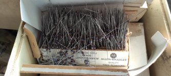
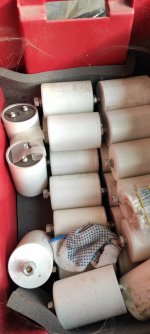
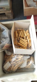
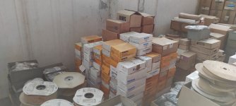
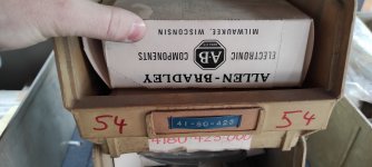
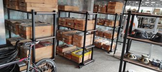
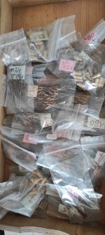
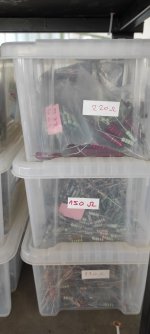
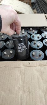
For Sale Large stock of NOS resistors, capacitors (Allen Bradley, Iskra, Rifa, Vishay, Siemens, Sprague)

Hope this is not against the forum rules, I read the rules and this is not a commercial sale. Friend of mine is going out of business (retirement) and I bought big stock of tubes from him, but have no use for resistors and all other passive components.

All components are NOS, legit and the real deal.

There is about 1 million of Iskra resistors (carbon and metal), 300 000pcs Allen Bradley resistors, very large stock of capacitors etc.

If someone is interested, stock is in Croatia. You can contact me here.

P.S. if this is against forum rules, I am sorry. Just want to help someone if they need some really good parts.

Attachments

  • IMG_20220212_102405.jpg
    IMG_20220212_102405.jpg
    252.6 KB · Views: 360
  • IMG_20220212_102407.jpg
    IMG_20220212_102407.jpg
    274.1 KB · Views: 372
  • IMG_20220212_102417.jpg
    IMG_20220212_102417.jpg
    307.1 KB · Views: 370
  • IMG_20220212_102421.jpg
    IMG_20220212_102421.jpg
    246.5 KB · Views: 370
  • IMG_20220212_102506.jpg
    IMG_20220212_102506.jpg
    217.8 KB · Views: 356
  • IMG_20220212_102511.jpg
    IMG_20220212_102511.jpg
    278 KB · Views: 341
  • IMG_20220212_102538.jpg
    IMG_20220212_102538.jpg
    219.4 KB · Views: 336
  • IMG_20220212_102552.jpg
    IMG_20220212_102552.jpg
    188.5 KB · Views: 329
  • IMG_20220212_102626.jpg
    IMG_20220212_102626.jpg
    356.8 KB · Views: 327
  • IMG_20220212_102916.jpg
    IMG_20220212_102916.jpg
    297.5 KB · Views: 333
  • IMG_20220212_102927.jpg
    IMG_20220212_102927.jpg
    164.3 KB · Views: 392
  • IMG_20220212_113845.jpg
    IMG_20220212_113845.jpg
    253.9 KB · Views: 403
  • IMG_20220212_102456.jpg
    IMG_20220212_102456.jpg
    281.8 KB · Views: 399
  • Like
Reactions: bOTL

Inrush limiter to Amp

Howdy. New guy here. No training, but have been regularly attending YouTube U, and am building an amp just for fun. And trying to figure out how to limit inrush current.

The transformer I'm using draws a bit of a spark from the receptacle when I plug it in, and I'd like to make sure I don't damage any components. This is the transformer I'm using. 40v to the power amps.

Transformer.jpg

It's also got some ±15vdc outputs, which I'll use to power a preamp. Kind of hard to see, but here it is.


15v± output.jpg


My question is, if I want to limit inrush current when I plug the transformer into the wall outlet, do I need the circuit between the wall outlet and the transformer? Between the transformer and the other components? Or both? I'll be building a dual voltage regulator to step down the ±15v to ±12v, which the preamp requires, so I assume if I used an inrush limiting circuit between the amp and the components, I'd place it between the transformer and the voltage regulators. Is that a correct assumption?

Many thanks.

PassLabs X350.5 repair and adjustment

Hello everybody.
I'm from Russia. And since 2014 I own Pass Lab X350.5. I bought it from an authorized dealer in St. Petersburg. It was a show piece that I auditioned before purchasing. All these years he only made me happy. Recently, the sound began to disappear in the right channel after 20 minutes of warming up. After a light Siberian strike, everything returned to normal. But today it stopped working altogether. I decided to open it and saw a very sad picture, it turns out that it had already been repaired by someone ... But I bought it new!
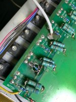
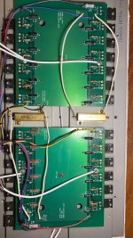
The resistors on the power boards are twisted, they are not in denominations, in several places under the resistors the board even burned out. In general, I decided to replace these Chinese resistors with good ones. Stopped at Mills mra 05 and Audio Note Tantalum Non magnetic. Now I have collected all this, but I do not know how to configure it correctly. I see descender resistors in several places labeled 5k p4-p7 bias; DIFF; OFFSET; P1 500. Please tell me how I can make the correct amplifier settings step by step.

Attachments

  • WhatsApp Image 2021-04-27 at 19.16.19 (1).jpeg
    WhatsApp Image 2021-04-27 at 19.16.19 (1).jpeg
    219.3 KB · Views: 1,188
  • WhatsApp Image 2021-04-27 at 19.16.19.jpeg
    WhatsApp Image 2021-04-27 at 19.16.19.jpeg
    155.5 KB · Views: 812
  • WhatsApp Image 2021-04-27 at 19.16.20 (1).jpeg
    WhatsApp Image 2021-04-27 at 19.16.20 (1).jpeg
    168.8 KB · Views: 771
  • WhatsApp Image 2021-04-27 at 19.13.50 (1).jpeg
    WhatsApp Image 2021-04-27 at 19.13.50 (1).jpeg
    164.5 KB · Views: 802
  • WhatsApp Image 2021-04-27 at 19.04.16.jpeg
    WhatsApp Image 2021-04-27 at 19.04.16.jpeg
    173.4 KB · Views: 839
  • WhatsApp Image 2021-04-27 at 19.13.49.jpeg
    WhatsApp Image 2021-04-27 at 19.13.49.jpeg
    145 KB · Views: 565
  • WhatsApp Image 2021-04-27 at 19.13.51 (1).jpeg
    WhatsApp Image 2021-04-27 at 19.13.51 (1).jpeg
    221.2 KB · Views: 630
  • WhatsApp Image 2021-04-27 at 19.13.52.jpeg
    WhatsApp Image 2021-04-27 at 19.13.52.jpeg
    212.6 KB · Views: 564
  • WhatsApp Image 2021-04-27 at 19.16.20.jpeg
    WhatsApp Image 2021-04-27 at 19.16.20.jpeg
    135 KB · Views: 599

Would this work to make a HT bypass?

Hi, I have a Denefrips Athena passive/active preamp (passive for signal path and active for solenoids. The problem is I want to have my HT go through it... I currently am taking the XLR preouts on my Marantz AV8805a preamp and feed them into one input on the Athena stereo preamp. In order to do this I need to raise the level on the Athena preamp to 38 on the volume (the volume goes from 0-60 with 60 being maxed). if I forget to reduce the volume on the Athena to no higher than 14...it could blow a driver when switched to listen to Roon.

So I was wondering if I inserted a XLR mic gain box between the Marantz and the Athena...would that solve my gain issue?

like this one...

https://www.amazon.com/Cloud-Microp...fos.f5122f16-c3e8-4386-bf32-63e904010ad0&th=1

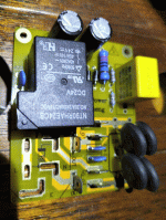
Normally shorting time delay board

I'm not sure where this belongs, but I had someone ask about this type of circuit for a tube line amp that peaked higher than solid state voltages on start up.

This circuit is as simple as I could make it. 12VDC to run it. Land R are shorted to 12VDC- (usually tied to ground in my builds). After about 11 seconds, the relay opens and sound plays.

It uses two resistors, a cap, and a 9014 transistor as an emitter follower. That drives a relay with a flyback diode across it.

Here's a pic. I have 4 boards left from the prototype run, and I can populate them if anyone wants...
1674794298490.png

CPU-COOLER for CHIPAMP

I know it is not usually nor widely done but that does not mean it is bad , or can not be a good option. Provided one´s case allows for the space and the used CPU-cooler fits nicely inside then : WHY NOT ? I would like to start a thread on this subject , using a nice chip-amp ( TDA7293 ) which needs a very good and efficient heatsink. These things are big and bulky anyways , apart from quite expensive as well , and if they are in the range of a degree/w of less than 1,5 they oblige to use a rather high case , see the Dissipante series casings .

I like to get "the most" out of things so that applies to chip-amps as well. To achieve a case which is of low height , say up to 3 inches =# 7,5 cms , and which fits in with other "normal" hihi-gear blending in with it is not easy at all having to use traditional large radiators.
Which brings me to the use of suitable CPU-coolers. Heatpipe-versions can easyly get rid of 100 watts or more od heat and come in all shapes and sizes so as an example have a look at this one :
1674571573296.png


Compatible CPU: Intel and AMD
Heatsink Material: Copper & Aluminum
Product weight: 1 Fan 410g 2 Fan 480g
Type: 2 Heat pipe TDP: 100W Fan
Size: 90x90x25m

This thing ( only as an example ) is under 17 dollars at Ali-express and is about 3 inches in thickness including the fan which can be taken off and either be substituted by 4 smaller 2" fans which would reduce the height by 1,5 cm ( 3/5 of an inch ) or by placing two fans at the back of casing channeling air to back side , using 2 2" fans side by side (intake from bottom in both cases ) . see here :

https://www.aliexpress.us/item/3256804444035466.html?spm=a2g0o.productlist.main.47.24f950afi1KlID&algo_pvid=de44c6f0-a3c9-46fb-be7f-f2aaf11d2e10&aem_p4p_detail=202301240544064528510827017250020440333&algo_exp_id=de44c6f0-a3c9-46fb-be7f-f2aaf11d2e10-23&pdp_ext_f={"sku_id":"12000029911056072"}&pdp_npi=2@dis!EUR!29.34!17.61!!!!!@2145280e16745678462392948d0708!12000029911056072!sea&curPageLogUid=QSRSNuH17WDz&ad_pvid=202301240544064528510827017250020440333_24&ad_pvid=202301240544064528510827017250020440333_24&gatewayAdapt=esp2usa4itemAdapt&_randl_shipto=US

I would love to resd lots of your opinions here .

Crossover Feedback please!

Hi everyone! I am designing my first ever crossover for a 2.5way speaker using VituixCAD. I know these are all hypothetical and that real world response is affected by the room and baffle design, but I wanted to have a good starting point. I feel the frequency response looks reasonable as a good starting point, but wanted any feedback in a few areas that could improve its design:
Drivers being used: DA RST28F-4, and DA RS150-8 x2.

1. The response north of the crossover has multiple peaks and valleys with a spread of 3-4db. Is that a big deal? If so, is there a design that can flatten it out more?
2. The tweeter I am using seems to take a dive north of 17kHz. Is there a way to bump that up without simply raising the volume of the whole driver?
3. I integrated a highpass filter for the two woofers because I intend on integrating a subwoofer crossing over at around 80hz. Is this necessary? Or should I simply cross the sub and speaker using the avr/amp that will be used?
4. There is some sizable cone break up for the woofer past the crossover starting at 3300hz. The overall response is relatively flat however. Should I try a high order crossover to try and eliminate it more?
5. Lastly, I am over thinking this a bit too much? Is it reasonable to use this as a starting point and make adjustments later with further modifications/simply using a DSP to smooth things out?

Looking forward to everyone's thoughts!

1674338982261.png

PMA 925

I recently purchased a cheap Denon PMA 925R. Problem is, there is no sound in it.
It turns on, and the (not original) remote works perfect and can change input like a charm. Volumecontrol is moving too.
with a multimeter I have checked the transistors I could reach from the top, the seems like working.
what would be the next to check?

I have never done anything like this before, so please tolerate some beginner questions.

How to EnABL

16-April-2022: After many inquires i have pulled the most important posts that describe the EnABL process to encourage people to pick up the technique


Tutourial #1 -- Materials

3 posts by Bud copied from the Hawthorne forum:

Materials:

The block paint I use comes from Polly S corporation, a division of Floquil / Testors. Any of their flat paints will do. But, if you do not want to stare at this lacy pattern every time you listen to music, use the flat clear paint. This is a bit more difficult to use, and I will cover what and why a bit later. Quite a wide variety of substitute materials have been tried successfully, by other people.

Next is Micro Scale micro gloss coating. Please do not substitute other materials for this one.

Both of these materials should be available from a decent hobby shop that sells primarily plastic models and trains. Both are also available on line, but there are box lot's you must buy. You will use it all, since EnABLing appears to be addictive, but it can look like a lot to purchase initially.

Next are speedball lettering pens. A-1 through A-5 in size and style. These will be in an art supply store, office product store or on line. You will also need a tip holder or two.

A useful addition to the arsenal are Rapidiograph technical pens. They make placing tiny dots on domes and whizzers much easier, for some and more difficult for others, like Dave from Planet 10, who uses them only under duress. Sizes from .02 through .085 are useful, but spendy.

Without the technical pens, and you can do without them with practice, you can expect to spend about $30 US.

Next go here and look over the pictures for the Fostex FE 127e. This is the stock EnABL configuration, for plain cone drivers, no whizzer. I will post the PDF data packet with conic sections and pattern rings in the next installment.

http://picasaweb.google.com/hpurvine/Fostex127ETreatment

Then here for a visual teaching aid, showing how to judge pen tip width Vs block pattern width, as the paint does spread a bit. Also shows how to use the pens for best flow and application control. Incidentally, you must burn the wax coating off of the tips before using them, or they will not work. If you roll the finger over the pics a little window of more or less pertinent commentary will pop up.

http://picasaweb.google.com/hpurvine/LowtherPreTreatment?authkey=VnmOeDveOOk

Look over the Fostex pics, note that you can combine the voice coil edge patterns for cone and dome into a three ring set, rather than four. Also note the weird dome center pattern. This, plus a drop of PVA on top of the center spot, controls dispersion for the entire driver and eliminates high frequency beaming.

PVA is poly vinyl acrylic, Parts Express sells it as surround to basket glue, Elmer's sells it as white wood glue and craft stores have it in their paper/scrap book sections. That dot is applied with a round tooth pick, with the point cut back to the barrel body, so about an 0.050" diameter droplet will do.

Go looking for the paints locally and if you are not finding them we can likely set up a group buy for a supplies packet, though I am not keen on being the distribution point.

The real thing to notice here is that the applied pattern, though neatly done, is not comprised of uniform sized, hard edged blocks, as the computer generated patterns would lead you to believe are needed. The inner rings are just sort of round blobs, with no attempt made to get them rectangular. This is another one of those very human endeavors, where close is good enough. So, download the hi rez photos and look at the application quality closely. You will get "good enough" pretty quickly.

Also there are a number of other driver types in this library and you are free to look at and download all of them.

http://picasaweb.google.com/home?tab=mq[/color]

WTB Vokume potentiometer and picnic

I’m looking to find a simple passive volume potentiometer and a pcb to mount it on. I see tons on EBay however I prefer not wait a month to get it. I’m hoping to just as a simple volume control to a TPA3255 board I have. Not looking for a op amp board with volume pot like most I see as well. Hoping someone can point me in right direction or happens to have a setup they don’t need etc. thanks.

Aleph 1 or 1.2 on Infinity IRS

Aleph 1 or 1.2 on Infinity IRS

Friend of mine operates a Infinity IRS III (not a typo it's a 3, not the more "common" 5) with a Threshold SA/4 on his Mid/High EMIM/EMIT wings.
He wants to have Aleph 1's now because he heared an Aleph 2 stereo on his IRS's and was very impressed. He says his IRS mid/hig section can dip down to 2 Ohms (I asked him where that is frequency wise) so he needed the specified push-pull 600 Watts at 2 Ohm rating of the three stage Aleph 1 and the two stage 1.2 being troughout single-ended Class A would have maybe problems in that area.
I deduced at this forum that the Aleph 1.2 is preferred soundwise.
Any thoughts/suggestions?

Class-D load vairation

Hi Guys

I have a new LG TV that has pretty reasonable internal speakers. These are driven by bridged class-D PAs, so the only analog signal in the entire circuit is what goes to the speakers. This is fine for what I want to do, and lets me use the TV volume control.

I added jacks across the bridged outputs with a switch to disconnect the internal speakers. I have a box with a pair of 10k:10k line transformers to tap the TV signals and isolate the ground between the TV and signal - besides, the TV is floating. I may have to attenuate the secondary side of the TXs going into the stereo, but I'm not that afar along yet.

I know that class-D amps are load sensitive, which leads to my question:
Do the amps need a load resistor of the same value as the disconnected speakers to exhibit low-distortion? or to have proper frequency response? or even just to function properly?
Or can I use a higher value load resistor inside the box to reduce wasted heat?

Thanks

Feature request: notification when someone uses your screen name

I noticed that in a post one can start typing a username of someone who has posted in the thread earlier, and the forum software pops up the name and you can click on it. When the post is posted, that name is shown in bold. I can't show that there because only my post exists so far in this thread and there are no other contributors. But obviously the forum software recognizes this use of a username in a thread.

The mods have requested that we do not quote too many posts to reduce bloat in the forums. Quoting a username is a nice way to shout out to that member without having to quote a post.

What I would like to see is that when someone uses my name like that, I get a notification. That features does not seem to exist AFAIK but I think it would be very handy and would help to track responses that are targeting me (the same goes for any other user). Is that a feature that the mods can enable or create?

QUAD 303 transistor query

I’m fooling around with an old 303 and wanted to know specifically about hFE ratinings of the TR104 on the driver board and TR200 on the power supply. Both of these were part # U17229 back in the day. I found the ZTX504 in both positions on my amp. I’m going to replace them with something more modern and DADA recommends the BC556B for both locations. At one time they recommended the BC556 in the power supply section and BC556B in the driver stage. Not sure why the change, other than the fact that the BC556 is/was hard to find.

Anyhow, here are some numbers to ponder:

hFE
ZTX504 50-300
BC556 110-800
BC556A 110-220
BC556B 200-450

What would you use, and where? I have both the A and B.
Thanks

Celestion Ditton 66 midrange MD500 unit vs MF500. Hardened/cracked diaphragm.

Predicament..

The original MD500 midranges in my 66’s have the glue/doping on the speaker surface that hardens and cracks over time.
The MF500’s in my Beovox 5700’s are in ‘mint’ condition.

A few years ago I swapped the midranges over and they have sounded ‘fine' in their new homes.

The crossovers had been professionally recapped in both sets of speakers but no change was ever made to the 24uF/30uF cap which varies according to whether an MD or an MF midrange unit is fitted.

Recently I’ve upgraded my amplification and source in my main system which uses the Ditton 66’s. (Yamaha C4 preamp and P2200 power amp, Chord Hugo DAC - all recently recapped and serviced.)
Naturally, I want the 66’s to be performing optimally.

The question:
- For best sound quality should I swap the midrange units back into their original correct speaker cabinets or leave them as they are?

I ask because I’m thinking that the cracked surface of the MD500’s might actually cause more degradation of sound quality than using the ‘incorrect’ MF500’s - I've read that both midrange units' performances once installed in the cabinet are very similar.

- Also, is there a successful procedure for renovating the cracked/hardened surface of the MD500?

Would be grateful for any advice.

Trade Antek AS-2T230 for AS-1T230

Hello all,

I have 5 Antek AS-2T230 transformers I would like to trade for four (4) Antek AS-1T230. Three of the transformers are brand new, 2 in the original box, 1 in a different box. Two of the transformers have been used a little, but there is plenty of lead length left. All transformers have the pads and bolt.
Fedex Home Delivery may be the least expensive shipping cost. Package would be 15x10x12 (Home Depot box) max at 35 lbs.

I also have 2 brand new Antek CA-200 steel covers I would like to trade for 2 Antek CA-100 steel covers, new or used, as long as they are in good enough condition to paint.

Please send a PM if you are interested in a trade. Thank you.

xfmrs.jpg

Advice/inspiration for 10-20W into 4ohm amplifier

Hello!

Mostly hang out over in the tube section here, but I've got a project based around tubes worst enemy, a low impedance "high" wattage load 😄

Got gifted a fairly nice 4ohm full range speaker element for a mono BT speaker project I've been toying with. The BT receiver has a D-class amp rated at 3W based around the PAM8303 chip. It sounds fairly good, but it's just not nearly enough power.

I haven't designed a solid state amplifier for audio before so I'm looking for some general topology and component advice. Not looking to build someone else's design but inspiration is always appreciated 🙂

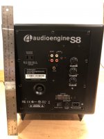
Repairing Audioengine S8 that won't come out of standby

Hi all,
First time poster here. I've got an Audioengine AS8 subwoofer that after working for years, won't come out of standby. The power LED stays "red" (standby) and never switches to "green" after sensing an audio signal.

I've troubleshooted in various ways:
- Tested the different input configurations
- Taken the sub apart to look for bad caps. Found one loose cap and re-soldered it with no change.
- Tested all fuses. None are blown.
- General visual inspection.

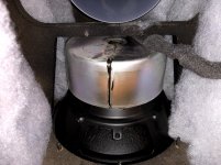
I can't find a circuit diagram. If I was more capable I would find a way to bypass the standby function and just leave the amp on. Attached are some photos. Does anyone have any suggestions?

Attachments

  • IMG_3017.jpg
    IMG_3017.jpg
    236.5 KB · Views: 301
  • IMG_3019.jpg
    IMG_3019.jpg
    737.8 KB · Views: 294
  • IMG_3020.jpg
    IMG_3020.jpg
    503.9 KB · Views: 359
  • IMG_3021.jpg
    IMG_3021.jpg
    550.3 KB · Views: 290
  • IMG_3022.jpg
    IMG_3022.jpg
    277.8 KB · Views: 279
  • IMG_3023.jpg
    IMG_3023.jpg
    316.9 KB · Views: 329

Modded ES9028 Pro DAC with SSR03 power supply

Selling all my home audio gear.

This is a Chinese DAC with 9028 Pro processor chip. I by-passed the OPAMP power section and soldered on a molex to provide power straight from the beautiful Per Anders SSR03 Ultra high performance regulated power supply.
Also added Burson discreet dual OPAMP's
Added NewClassD power regulator on the IC power section.
Upgraded some of the power capacitors here with Nichicon Fine Gold caps as well.
Quality By-pass caps (Multicap and Solen) added to the 4 OPAMP's
Including transformer for both the SSR and the IC section of the DAC.
Quality sounding unit!
Solder points on the board for adding an Amenero USB DSD decoder board.
No chassis (this was custom mounted in my HTPC case)
Asking $400 shipped
20220320_125043.jpg

Attachments

  • 20220320_125052.jpg
    20220320_125052.jpg
    512.9 KB · Views: 210
  • 20220320_125056.jpg
    20220320_125056.jpg
    410.5 KB · Views: 168
  • 20220320_125124.jpg
    20220320_125124.jpg
    360.1 KB · Views: 186
  • 20220320_125227.jpg
    20220320_125227.jpg
    369 KB · Views: 193
  • 20220320_125241.jpg
    20220320_125241.jpg
    365 KB · Views: 176
  • 20220320_125550.jpg
    20220320_125550.jpg
    467.6 KB · Views: 190

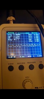
Android tablet injecting digital noise to power lines

Hy,
Long story short, I'm making android tablet car head unit, I removed the battery and I'm powering it with 4.2v via regulator (to the battery connections).

The tablet mcu is generating digital (dial up modem like noises) into the power feed, based on the tablets activity.

LM317K nor the LM2596S will filter this out, so I'm guessing the noises are not on the positive feed, but on the ground.

Any audio amplifier I connect to the same power supply will pick up these noises, as system will be installed in the car, I cannot feed this to cars ECUs.

I need it gone.... This project was halted 2 years back and now I'm trying to finaly solve the issue.

Also any aditional current must be minimal as it will be on all the time (even when car is off).

Only tablet is connected via regulator any I can see this noise on both sides of the regulator:

Screenshot_20230117_185703_Gallery.jpg

Please shine a light on me, this project would be considered finished if it wasn't for that noise.

All scrap/trash subwoofer enclosure

Not a question, just something I attempted that came out really well.
I got a 15y/o 6.5" Samsung subwoofer from town trash. Orig enclosure was on its back in a puddle...not usable.
Not worth spending cash or even waste new plywood on. So I decided to try to make an enclosure out of left over scrap. That fits snuggle in my shelving unit.


I Used:
-24"x13" piece of sheathing plywood left over from fixing my roof.
-A 15" sqyare piece of 1/8" sanded plywood left from skinning my fish tank stand.
-the drawer from a child's maple night stand
-A childs floating bookshelf
-base is cut from heavy MDF kitchen cabinet toe kick/trim.
-scraps of left over 2"x4"s and 1"x3"s
-used left over paint from the bathroom
-used $1 store drywall screws (2.33¢ per screw, my low expectations meant 6¢ wood screws would be a waste)
-used $1 stire latex caulk to seal
-I kept the original cardboard 2.5" port tube, Incase it got damp/weak I dried overnight with a fan. sanded both sides, painted the inside with enamel paint. Reinforced it's outside with pva glue and a paper tube/roll
Wires and clip -port taken out of a different speaker from the trash

20230114_111005~2.jpg
20230114_110929.jpg
20230114_110922.jpg
20230114_110950~2.jpg
20230120_191434~2.jpg


It (alone) is powered by a 100w+50w*2 tpa2116d2 because receiver needs an active sub. All other speakers are passive.

It works pretty well.

Only caveat is: it originally had no crossovers/filters. Receiver doesn't have separate subwoofer except for volume. Was hoping the the drivers natural roll off pkus bass frequency tunning knob on the TPA3116 would be enough of a low pass filter but it's still too loud at 1.5khz.
I think I need to add an inductor.

EDIT
*PS check out the bumble bees painted on the green shelf mdf inside.
*PSS don't use a table saw to cut 1" strips of wood into 0.5" strips of wood. I have a few thousand dollars in medicals bills and 9.75 fingers left making this $2 enclosure (but that's my recklessness, not the enclosures fault)

Cost per displacement.

Most cheap low xmax 15" even with stamped steel frames are over 100$ here now, I can probably get some cast frame 6mm xmax Fane Sovereign Pro 15-600 for 135$ + taxes.
The end-of-line Beyma 15MC700 are still 230$ before taxes and shipping, looking like a steal compared to some other things.

Anything with good xmax AND cast frame is getting really expensive.

Cheaper to get some half decent 18" these days, B&C 18RBX100 is looking like a viable option, very tempting to get some SB Audience Bianco-18SW450 though I am not sure what kind of box to make for those.

12"s completely unsuitable for bass are catching up with moderately expensive 15"s from the same time last year, or even cheap 18"s like the previously mentioned 18SW450.

The US of Ay does not seem to be affected to the same degree just yet, maybe later this year.

Conclusion:
Been trying to look at Beyma, Faital, Mica, 18Sound +++
So far it seems like the most displacement per buck is the SB Audience Bianco-18SW450 at 123 Euro, any contenders?


http://www.sbaudience.com/index.php/products/subwoofers/bianco-18sw450/
1674720959211.png

DIY Fix : Denon AVR-5800

I'm up for the challenge on this Denon AVR-5800 once touted as "The Beast" it's heavy and got a toroidal transformer that mostly only high end AVRs sport.

It's totally dead as in dead, only semblance of life is an LED standby light, and it doesn't respond with the processor reset procedure. The -----
  1. Press and hold the DIRECT buttons and STEREO buttons, and at the same time, plug in the AC cord." -- nope doesn't work.

I believe it is not the amplifier section as I have junction tested all the transistors and they all appear to be healthy; junctions give the 0.6V on my multimeter.

I'm thinking it could be a processor issue or a power supply refusing to power on the unit for a short in the power supply section.

Any wild ideas are open, I really would love this beast to come alive once again and would want to hear it. Doing this on a part time basis, and it's not going away anytime soon.

If you guys have any idea where I could start to check please do so. Any help would be much appreciated.

Things I've done so far.

1. Checked all fuses - they are all good in the power supply section.
2. Power switch / standby switch is good, I tested with the multimeter and it conducts when pressed.
3. Power transistors all good
4. There is power going to the mini transformer what I believe would send a signal to the main unit to come alive, the mini transformer - the one that gives 12V, 6V, and 33V is good as it is supplying power (AC to the components)
5. Diodes and Zener diodes appear to be okay on power supply as they give junction volts.
6. Currently stuck there, as I am waiting for my ESR meter to be shipped to check on the capacitors.


More help is needed to point me in the right direction if anybody has had this problem before. ANY I mean any ideas would help, except going down the road of throwing this away.

Thank you.

channel mismatch (resistance) when testing a balanced relay-based attenuator

some info:
1. I was measuring the resistance between in and out of the channel. (example: L+in and L+out).

2. The relays I used are Omron G6S-2 DC12 (https://mouser.com/datasheet/2/307/en_g6s-1128313.pdf).

3. I was initially powering the attenuator using with a 15V 2A 30W SMPS.

4. The attenuator has a 7812 regulator to bring down the voltage to 12VDC. It also has a 7806 to bring down the voltage further to 6VDC (6VDC is used to power the 2 ICs)

5. After a certain rotation of the rotary encoder, the resistance between the L and R channels are highly out of sync. maybe 50% off (example: L+in/L+out could be measure 8Kohms while L-in/L-out could be 4Kohms)

6. I replaced the SMPS with a V+/V- linear supply (using a 48VA 2x15VAC 1.6A transformer) I'm using for another project. I tapped to the unregulated +VDC after the 1st capacitor (around +26 VDC without load). After the replacement, the problem I was having disappeared.

questions:
1. could the SMPS be defective?

2. maybe my SMPS does have enough juice to power the attenuator? (though I did some quick math based on the relay coil ratings and it seems to be more than enough (11.7mA x 12VDC x 16 relays = around 2.25W))

3. Can I perhaps parallel SMPS output?

4. Maybe the problem be elsewhere?

Thanks!

Switching global NFB on/off (pentode LTP)

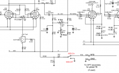
I am building Pete Millet's DCPP "Engineers Amp" and would like to add a switch to turn the global NFB on and off.

See attached for an annoted schematic snippet

Is this the correct way to switch the global feedback on an amp with a pentode long tail phase inverter?
In the NFB off position the V7 grid is grounded via 1K+ 3.3K || 47K, which is ~4K. I think this should be fine.

Thoughts?

Full schematic for reference

Attachments

  • NFB switch.png
    NFB switch.png
    54.8 KB · Views: 171

  • Locked
lowering the secondary output voltage of transformer

Hi all,
I have 2 transformer sitting around doing nothing. They are both 117v/500VA, dual secondary, same manufacturer, one is 50-0-50 and the other is 40-0-40.
Is it feasible to connect the the primary of the 40v transformer to the secondary of the 50v transformer. The objective is to get a 17dc output.

Thank you for the help.

Heathkit IT-17 Calibration

I'm trying to calibrate my Heathkit IT17 and getting some odd results.
In the manual, meter should read +/-10%

lug 1 of T and lug 10 of V 30 VAC
My result 66 VAC

lug 1 of T and lug 1 of AB 100 VAC
My result 127 VAC

lug 1 of T and lug 4 of AB 250 VAC
My result 257 VAC

When I measure the filament section in the 'off' position I get 5VAC at the filament
pins. Shouldn't this read at 0?

LM3886 5.1 build

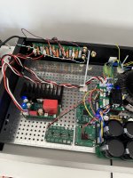
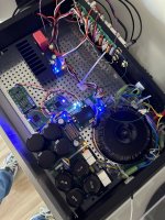
I’ve been slowly working on building a 5 channel audio amplifier to replace my denon AVR amplifier. I actually went to school for electrical and computer engineering, but sadly, we never really did any real world electrical engineering. So this project for me is sort of my own personal university course where I’m trying to learn and acquire all the skills I probably should have had.

I’ve been making all the PCBs myself for the digital logic, and will ultimately try to decode the Dolby digital from spdif and use that to run the channels. In the meantime though I just completed the first audio channel and did a test today

All I can say is wow. I had high expectations, but it’s like having a brand new set of speakers and stereo. I have a set of Dali Oberón 3 speakers which were recommended to me, and I always thought they lacked a bit of everything. But they absolutely sound amazing now. And when I say they, I only have one channel so far, so I can’t to hear what real stereo sounds like.

At loud listening volume, the amp went from 6 watts total (including the digital circuits) to 9 watts, so only 3 watts of power. And to think I was worried that 300 VA wouldn’t be enough. I don’t think I can get much louder without offending my neighbours.

The only things so far that are potential issues are:

1) I am just using an RCA Jack for the input for now, and I ran the RCA ground to the input of the LM3886 and used it as my signal ground. This sounded horrible. It wasn’t until I also grounded this to the main ground that it sounded normal. I would have thought my laptop, which was the audio source over the headphone jack, would have acted as the ground, no? Anyways, now that it’s grounded, it seems fine.
2) while sitting on the couch with no audio playing, I don’t hear a thing. But if I put my ear up against the speaker I hear a very faint noise. It sounds sort of square wave ish so I’m thinking it’s rectifier noise. Is it a reasonable expectation that this sound should disappear completely if it’s grounded properly, or is it normal to hear a faint background noise close up?
3) every 30 minutes or so I hear a single quick audio tick. It almost sounds like a digital artifact. The only place I can think it might be coming from is a small beer fridge that’s on the same circuit. I haven’t tested this yet, but I wonder if when it kicks in that it causes that tick on the audio. If that’s the case, anything I could do to suppress it?

Thanks everyone. This has been a rewarding project so far, and I can’t wait to keep working on it and getting the rest together. Also a shout out to Tom and his website as I referenced it lots during this build (but perhaps not enough when it comes to grounding!) cheers.

Attachments

  • B9E4E390-50F5-4BF1-A720-BD8757FBEA0B.jpeg
    B9E4E390-50F5-4BF1-A720-BD8757FBEA0B.jpeg
    515.1 KB · Views: 433
  • D06425DF-35E4-4C80-8FD9-7B498F12EE39.jpeg
    D06425DF-35E4-4C80-8FD9-7B498F12EE39.jpeg
    480.3 KB · Views: 404
  • 1FC81905-1E88-4E60-9979-0A00F152874E.jpeg
    1FC81905-1E88-4E60-9979-0A00F152874E.jpeg
    364.3 KB · Views: 379

Sub DIY Planning RSS390HE-22 Subwoofer + Passive Radiator good idea? or better sealed.

Hello,

I am planning to do my first Subwoofer Project and I think I need some advice

Dayton Audio RSS390HE-22 Subwoofer 15 inch​

Dayton Audio RSS460-PR 18 inch with 8x75g weight​


Planned is a 130 liter case 480 x 480 x 700 mm. 18mm MDF (Part express recommandation 127L)

2x 70 mm bars 2x each side to stiffen the long sides.

Passive Radiator on the Backside, same axis as the sub.

To me it doesn´t look that wierd. Actually I am running a SVS SB 2000 and think about trying it myself to build a good sub.

What do you think about that? Should I go sealed (60-65L) and adjust it to my desire with a DSP or go for Passive radiator and DSP and might have a harder time to adjust?

Usage is like 70% home cinema / 30 % Music.

Thanks in advance.

Design.JPG

1674691575148.png


1674691679809.png

Tektronix 576 set up question

Hi All,
having become a very new, but happy owner of a 576 which I'm still learning to use, I have a quick ( hopefully) question on setting up the unit to match transistors.
For some boards I'm re-populating, there are two transistors specified for a position - the BC413 and ZTX384. To my eyes the information in the data sheets for both these seem comparable. However, if I put them in the 576 and select a setting that'll give me a set of curves, neither will display correctly on the others settings. As I'm initially working on the setting examples in the service manual, I have to adjust these for higher values to get the curves for the ferranti ZTX, but these will then send the BC413 off the scale. Would this be considered normal, even for alternative parts?
Many Thanks
Joe

VTA ST-120, reissue Tung Sol 5AR4 ruined. Appreciate knowledgeable advice!

I've helped my sole tubular buddy in town, for years, for free. He passes on old and or broken equipment to me, and I'm fine with that. I got his VTA ST-120, when it broke. I'm not a mental giant with an engineering degree, etc. Some folks here are. I was tech trained years ago at a JC, but learned much more here. I grasp the cool fix for protecting a tube rectifier from breaking down under reverse voltage, by adding a pair of diodes. Very cool! Here is my problem: The rectifier tube was toast, but it diminished the % of 'good' rating of that right PP pair of reissue Genelex KT88s to 30% each. The pair on the left register virtually 100%. I stuck a 5R4WGB in as a rectifier, using the 30% tubes (it's less risky), and the KT88 lit up properly, and no fireworks. My friend saw the T.S. 5AR4 sparks (fireworks in side that tube, and the also the pair of KT88s on the right, and turned it off immediately). He bought new gear. I loved the amp driving his panel speakers! I tested these tubes on my Amplitrex AT1000A. From this description, which could have been MORE concise, would it be safe to bet that a protected rectifier tube, would be a proper and complete fix? 2 New Genelex KT88s too, (ouch). With rectifier tube in place, and if all 4 of the KT88 sockets match voltage, pin for pin, am I probably OK? The preamp parts, sockets and virtually all the bits are on a circuit board (other than the adjustment pots), and though this amp was preassembled, it's a 'kit' so info is available, but I DO love prefer to point wiring. I do have a vacuum solder sucker-adjustable soldering station, so if I have to, I will dive in, I will. Appreciate your helpful feedback, which I've received here before. Thanks in advance for your support, and good luck with your projects! :>)

I tried to improve the sound of an Anker Soundcore 2 by redesigning the speaker housing, 3D printing it & testing

Hi everyone,

With this post i would like to share some things i learned while trying to improve the sound of a Bluetooth speaker. I have done this in the context of a project for my bachelor mechanical engineering. We had to create a small project ourselves, preferably about something that you didn't have any previous experience with. Sound is only briefly touched upon in our study and only in the sense of the dynamics of vibration.

I wanted to try to do a enclosure design inspired by HexiBase's video's on YouTube. Little did i know that this is pretty hard to do.

I started out with a lot of research about different speaker enclosures, but I wont bore you with that.

I wanted to try to improve the Anker Soundcore 2. A cheap Bluetooth speaker which sounds okay in my opinion. It uses a passive radiator paired with 2 1.5" 5 watt, 3 Ohm speakers in a small water-resistant package. At first i wanted to make a transmission-line style speaker, but i soon found out that it is important to know the properties of the drivers that are being used. As mentioned before the Soundcore 2 uses 2 small 5 watt speakers, but this is all the info i could find. The speakers have some numbers printed on them, but i cant seem to find any info on them via Google.

The transmission-line housing was out the window at this point, so i settled for an open baffle housing. This would be a very easy enclosure to design and it wouldn't be necessary to know all the important properties of the drivers. In CAD I designed a very simple square shaped baffle with geometry in the middle to perfectly fit the drivers. The baffle was 200x200mm, because this would comfortably fit on the bed of my Ender 3 printer. The housing's were printed in white PLA with 20% infill. Overall the prints took 13 hours.

When these were printed i assembled them and spliced open an old USB cable to get some wire to extend the original wires. When this was done i tested them to see if everything turned out the way i wanted to.

Then i wanted to test the "redesign" to compare it to the original Soundcore 2. Unfortunately i don't have access to an anechoic chamber or the professional equipment needed to perform these correctly, but i reckoned that i could do the 2 measurements with the stuff that i have on hand. Since both measurements will be flawed in approximately the same way i could at least compare the two and see the impact of the changed enclosure design.

Some of the reasons why my measurements could be flawed are:

  • No anechoic chamber; The resonances and reflections of my room affect the measurement
  • No calibrated microphone: I don't know the frequency response of the microphone, so the microphone colors the results
  • My room doesn't have a lot of space behind the speakers, so the open baffle speakers suffer more from the reflections than the Soundcore 2

The software i used for this was Arta. This is a pretty extensive software which you can use to test all kinds of stuff related to audio, but i only used the option to test the frequency response. Arta offers a paid version and a demo version. The demo version doesn't let you save files, but it still lets you export data to a excel which was enough for me, so luckily it didn't cost me anything. For the microphone i used a nameless boom microphone that i had laying around. The results i got were very useable and allowed me to learn some things about my new open baffle speakers.

1674572393105.png


As open baffle speakers have a pretty big bass rolloff i wanted to predict the frequency at which this would occur. As the baffle was 200mm wide my calculations said that the bas would start to rolloff at 135 Hz. However, as you can see the bass rolloff starts way earlier at around 240 Hz, the reason for which I'm not quiet sure. What I found quiet interesting to see is that the upper range treble seems to be better presented with the open baffle design. Something I didn't test, but I heard quite noticeable was the improved soundstage with the open baffle speakers.

If you would like some more info on this small project feel free to ask them. Any tips on how i could have done things differently of better are welcome!

Replacing vintage “epoxy blob” LEDs

I recently picked up a Nikko NA-700II with a defective LED VU meter.

I’ve traced the problem down to dead LEDs… now the problem is… i’m not sure what to replace these with as they just appear to be a bare die on the PCB with a bit of clear epoxy blob on top. I assume i can scrape it off and replace it with a 402 SMD LED in its place.

Problem is that i’m not sure what sort of specs I should be looking for (forward volts, mcd, test current, etc…) I don’t want the replacements to be too bright or draw too much current…

My only hint is that is that the supply voltage is about 10VDC and there’s an 820 ohm resistor in-line on the middle LED that’s just a power indicator. I figure a 3v chip should be ok?

4CC23F3F-66B0-4E2E-8D64-90C05E359AB3.jpeg

Two Bridges and Center Tap Confusion

I have been away from the hobby for quite a while. Picking it back up, and have been reading about PS here. I have seen a number of posts to NOT connect more than one bridge to a secondry center tapped transformer. Posts mention it being a bad idea, noise wise, to very ominous, BOOM result. The latter certainly got my attention, but I think it is in relation to trying to run two bridges to seperate the rail voltages.

Context: I have an Adcom 545II amp, which has a 500VA transformer. From the schematics (see below), the transformer looked to be just a center tapped one. But, the transformer has 5 wires on the secondary side. The resistance is too low for me to confirm if there are two seperate windings, tied together in a common center tap, or a single winding with extra wires. If someone knows which, I would appreciate it.

Back when, I purchased an Avel 625VA 40-0-40 transformer to mod the amp. I was planning to connect secondaries in series to make a center tap, and feed two bridges and seperate cap banks. One bridge/bank per channel. I didn't think that this would be a BOOM issue, but please, please, correct me here. Now, I could seperate the windings and use two bridges to seperatly rectify the rail voltages, and have a common supply that feeds both channels, but thought the former was better, ie each channel would have its own bank. Certainly will go that way if the CT is a BOOM problem.

I would appreciate your knowledge and comments.

Attachments

  • 545II_PS_Capture.JPG
    545II_PS_Capture.JPG
    45.1 KB · Views: 185

Adcom GFP-565 Treble Potentiometer replacement

Looking for recommendations on sourcing a replacement potentiometer for Adcom GFP-565 Treble pot VR203 which is a 4tr 1742 20k bx2
Symptom = Left channel treble adjustment has no effect. Right channel works as expected.
I used my meter and measured the pot. It is open on the left channel. I tried some Deoxit but that didn't help at all.
Thanks for your consideration and advice.
-Steve
IMG-8902.jpg

Lucky me

I've been building speakers for 30+ years. I salvaged some amt tweeters out of a pair of mismatched Martin Logan speakers given to me (3" & 4" woofers.)
I paired them with 6.5" Hivi woofers. I built xovers out of what I had on hand. 2nd order 4k hz on the woofer, same slope but 4.5k on the tweets.
I installed them in homemade boxes I got at a thrift store. I had to pad the tweeters but otherwise, fantastic. The pushed a pair of JPWs into the closet.
All fine except these cabinets were too small.
More thrifting and I found a pair the right size. Q of .7, perfect.
After adding bracing, altering the tweeter hole and painting the front baffle I installed the drivers and...wtf! No bass.
I was using a sub and 100uF on the input I was at a loss. I listened to both sides of a folk album, gave up, went to bed.
In the light of day, obviously I hooked up the xover backwards. How those tweeters didn't burn out, no clue. It's been 5 or 6 weeks and they're fine.
I've since turned the sub down and no caps on the speakers. I guess I'll sell the JPWs, the best speakers I ever bought.
  • Like
Reactions: GM and AllenB

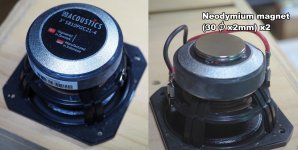
SB Acoustics SB10PGC21-4 (3" Full-Range) / normal version and magnet added version.

SB10PGC21-4 has a small magnet and weak driving force, so the sharpness of bass sound is not so good.
The addition of a neodymium magnet improves the sharpness of the bass and the sound quality in the all range.


[ Air-Recording ]SB Acoustics SB10PGC21-4 / normal version

Login to view embedded media
[ Air-Recording ]SB Acoustics SB10PGC21-4 / magnet added version

Login to view embedded media

Attachments

  • SB10PGC21-4+Magnet.jpg
    SB10PGC21-4+Magnet.jpg
    209.2 KB · Views: 339

For Sale - pair of miniDSP 2x8 kit boards with PSUs

I have a pair of miniDSP kit boards for sale along with their PSUs. I only used one channel of the balanced analog portion of the boards and 3 of the output channels. Fully functional as far as I know! $100 ea plus shipping.

Both boards now sold...

Attachments

Help needed - how to install soft start switch for pass A3

I have bought a Pass A3 kit from China that requires a soft start switch installed but am not technically knowledgeable enough to know how to wire it up.
I have attached photo and commentary from where I bought it from, it talks of it requiring a double switch and has two switches marked on the board.
And I am also unsure of WHERE in circuit this gets installed, before the transformer in other words direct 240v straight from wall?
Sorry for my ignorance any help greatly appreciated. I have successfully built some wonderful speakers that sounds absolutely amazing but the amp stuff if beyond my current knowledge.

ntroduction:
It adopts advanced double-sided thick gold-plated 2.0mm PCB, copper foil thickness 75U, high current wiring, 30A high current contact relay and other components assembly, no need to connect transformer, and can be directly soldered to the IEC socket with fuse, no need for punching installation. Small size, can make reasonable use of the chassis space. Of course, it is also possible to connect additional leads.

Product Features:
Prevents the power amplifier from being affected by large currents on the components at the moment of power-on. The delay time is about 1 second. After the power switch is turned on, the switch no longer passes a large current. When the switch is turned on, the switch only loads the small current of the relay coil. When the power amplifier or other equipment uses a large current, it is completely burdened by the 30A relay. The durability of the switch and the limitation of the switch can be passed through a larger current.

Note 1: The “Double Power Switch” must be used, and the single switch cannot be used. The power switch current is up to 3A.


Input voltage: AC 100---250V
Size: 74mm*61mm

Attachments

  • ss2.GIF
    ss2.GIF
    311.2 KB · Views: 154

Hifonics BXI2006D open relay

Everything on this amp works except the relay wont close to send output audio to the speaker terminals, the relay is control by the PWM card (one that has the gate drivers on card, not on amp board). B+ is on the relay coil from by default straight from B+ in, the card is used to control the GND to activate the relay, i really not seeing a fault so to speak on the card and the circuit traces are ok, is there any likely component to check? (the realy is good when i send GND to it, it activates).

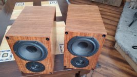
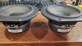
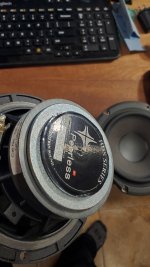
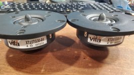
JR mini Speakers $200ca OBO

For Sale: Woofers and tweeters from JR mini speakers. Peerless HDS - 832873 $50ca plus shipping
Vifa XT25TG30-04 Pair $30ca

SOLD!

Attachments

  • thumbnail_20230124_122404.jpg
    thumbnail_20230124_122404.jpg
    198.3 KB · Views: 115
  • thumbnail_20230125_165034.jpg
    thumbnail_20230125_165034.jpg
    202.7 KB · Views: 79
  • thumbnail_20230125_165123.jpg
    thumbnail_20230125_165123.jpg
    179.4 KB · Views: 89
  • thumbnail_20230125_164856.jpg
    thumbnail_20230125_164856.jpg
    191.4 KB · Views: 96

Dynaco Stereo 120 amp

I have a Dynaco Stereo 120 amp that has had the Bender ULT120 upgrade. It never had the TIP mod work done (though it is an older version that would call for it). I assume the Bender mod supplanted the Dynaco TIP mod.
It has been working fine until recently the right channel volume has reduced dramatically and is very scratchy.
I thought it might be the large output capacitor. These output caps were newly replaced when the Bender mod was done but I swapped the left and right channel caps and there was no difference. The left channel is clear and strong but the right channel is almost out.

I'm not well versed in electronics so I could use some help. Anyone have ideas where to start diagnosing the problem?
Thanks
Carl

Mission 753 suggested xo mods

Hi all

I have been looking this weekend at my trusty Mission 753 non freedoms. So far with this speaker I have carried out 2 successfull mods.

1. I removed the metal grill that "protects" the metal dome tweeter. A very good result on this one. I always found the freedoms to be too soft for my tastes. The non freedoms a bit harsh. The non freedoms with the tweeter mod gets close to my tastes.

2. I applied "no more nails" between the basket and the magnet. This has made a subtle but worthwhile improvement to the clarity of the speaker.

Next up I plan a rewire and some improvements to the crossover. I took some time to map the crossover.

My schmatic

My plans are as follows
  • Replace the coffin style resistors with decent quality wirewounds
  • Replace the 6.8uf cap on the tweeter's filter with something nice. suggestions please?
  • Replace the back to back 470uf caps on the mid's filter with a decent bipolar cap, suggestions please?
  • Replace the back to back 1000uf caps on the lower end filter with a pair of good quality 'lytics, probably nichicon fine gold or similar. Open to suggestions though?
  • leave the existing inductors for the moment. I don't have the facility or know how to measure their values, let alone pick replacements.
  • Replace the 10mf bipolar cap on the mid range filter with higher quality, again suggestions?
  • Split the mid and low end filters and go tri wire!?

The last one I have some questions over. Excuse my ignorance when it comes down to impedence. The reason for wanting to do it is that I recently moved to bi amp (using gainclones) and the difference in clarity was dramatic. Separating the filters looks easy in terms of wiring, I just add a couple of binding posts and wire to them. Impedence though I dont understand fully.

What will be the effect in separating them? Will the volume go out of balance? What would be the impedence be at the inputs to each crossover, or what do I need to know to measure it?

Within my plans have I made any stupid errors?

I don't plan to make any changes that are irreversible, but I would appreciate any guidance that will increase my chances of success.

Thanks in advance

Blair
  • Like
Reactions: midrange

Two way monitor (studio) ponderings?

Hello World!
This is my first post here, been a member for a long time though.

First of all, I'm in Iceland so parts are scarce; gotta make things work! hehe

Ok, I'm gathering up some components and parts for a pair of two-way, 10" or 12" studio monitors.
I've been looking at opinions on the JBL 4410A and 4412A and have come to the conclusion that the 10" driver from them (127H-1) might be the business*.
*unless someone convinces me otherwise.

I've just bought a pair of vintage JBL 3110a Crossovers, albeit their x-over freq. is 800 Hz (I would've aimed at the upper 1.8 KHz, but then again I'm a novice!)
It was sort of an impulse buy; the HF output is "ideally" for a 16 ohm Compression Driver / Horn...

I'm interested in ribbon tweeters, but have learnt that they are limited to really high frequencies.
Except for the original Heil Air Motion Transformer; used in one two-way design from Heil?

Today I found a beat up pair of old SEAS 403 which have a reflex port and quite possibly the drivers from them are useable, who knows.
But I was mainly eye-balling the cabinets; they have nice dimensions, adequately deep in my opinion.
(I don't mind a plate over the HF hole; á-la 4331 😉

Thanks,
any ideas or pointers?

Sorry for the long write up!

-Geir

Help with Bass/Mid Selection for Small Box

As a relative newcomer to speaker design I am looking for suitable drivers for a small 2-way.
Actually the speakers will be used with a 2nd order electronic crossover with a low pass frequency of 120Hz and I'm targeting a 2nd order low pass for the speakers themselves in the range 80Hz to 120Hz i.e. closed box. Maximum baffle width is 200mm and target volume is 9L for a rectangular box or 7.5L for a sloping baffle version.

The Satori range of drivers looks like a good mid-price solution. The frequently used MW16P actually goes a bit to deep for my application!
So I'm looking at the MW13P-8 or MR13P-8 along with the TW29R tweeter.

How do I choose between the MW and MR?
Any suggestions for drivers that might suit my application better?
Projects by fanatics, for fanatics
Get answers and advice for everyone wanting to learn the art of audio.
Join the Community
507,581
Members
7,878,041
Messages

Filter

Forum Statistics

Threads
405,779
Messages
7,878,041
Members
507,581
Latest member
Wandaru