I'm trying to calibrate my Heathkit IT17 and getting some odd results.
In the manual, meter should read +/-10%
lug 1 of T and lug 10 of V 30 VAC
My result 66 VAC
lug 1 of T and lug 1 of AB 100 VAC
My result 127 VAC
lug 1 of T and lug 4 of AB 250 VAC
My result 257 VAC
When I measure the filament section in the 'off' position I get 5VAC at the filament
pins. Shouldn't this read at 0?
Last edited:
Please Post (or ask for) a schematic.
Troubleshooting without a schematic is like . . .
Blindfolding an Archer, and asking him to hit the bulls eye.
Troubleshooting without a schematic is like . . .
Blindfolding an Archer, and asking him to hit the bulls eye.
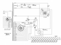
I'm working off the schematic for the IT-17/ IT-21/ 3117. Ref pgs 39, 45-AB 40-V 41-T. Just retested today and results are better:
lug 1 of T and lug 10 of V 29.3 VAC
lug 1 of T and lug 1 of AB 97.7 VAC
lug 1 of T and lug 4 of AB 244 VAC
Still having the same filament issue as before. 5 VAC in the off position.
lug 1 of T and lug 10 of V 29.3 VAC
lug 1 of T and lug 1 of AB 97.7 VAC
lug 1 of T and lug 4 of AB 244 VAC
Still having the same filament issue as before. 5 VAC in the off position.
Attachments
Last edited:
Can foster a guess why when I set the filament knob to the off position, I'm getting 5 VAC at the filament pins? Or a suggestion for trouble shooting?
I think you're good the HV test points are all within spec. I would have expected them to be high because line voltages are higher these days, but yours are really spot on, under 5%. You're HV line set is in spec, if you couldn't get a line set then you'd have to use a Variac, but you got lucky with your house voltage and an available primary tap.
As for having 5v on the Octal socket when the filament switch is set to off... What you really need to be concerned about is if the octal socket drops down to all the voltages under 5v when the filament switch is set to those voltages. Basically, will I burn out octal tubes that have a filament under 5v. If the octal filament drops to those voltages under 5v properly then all is good, even if the "off" position defaults to putting 5v out. The filament switch should always be set prior to plugging in a tube and not changed while the tube is plugged in.
It looks like there is a pilot bulb test socket that is hooked to the pole of the filament selector, perhaps the default off position leaves 5v for the pilot lamp socket hot all the time, doesn't seem right but not sure. Seems so, because the bulb test socket is not variable, it is fixed to the center pole. So take a measurement of the center pole of the filament rotary switch when it is "off", is it 5v as well?
Please measure the filament volts for all the positions under 5v, do those all drop to their proper values? Then when you go to "off" position you're saying the octal pins 1 and 5 jump up to 5v?
Last edited:
5 Volts with no load (no tube in the socket).
Check the filament switch:
Is it clean, no rosin, no grease, no dirt, no carbonization due to high current, etc.
Is the switch properly rotated to the correct position (when the knob says off, is the switch wiper truly in the off position; or did the knob slip on the switch shaft?).
Then put a tube that has a 5V filament in the tube socket, and see if it has filament voltage when the switch is in the 'off' setting.
Last edited:
These are the results from my test:
OFF ≈4.9
.63 .732
1.4 1.468
2 2.024
2.35 2.208
2.5 2.393
3.15 3.227
4.2 4.335
4.7 4.794
5 5.555
6.3 6.83
7.5 7.59
9.45 9.45
12.6 12.4
19.6 20.08
25 25.67
32 32.57
50 50.97
70 71.4
110 111.7
6A3sUMMER, I've cleaned filament selector switch it up a bit.

Windcrest77, I want to know where to put the other probe if one is on the switch (center pole).
I need to find a tube that has 5v for heater and then I'll report back. My test was done with no tube in the socket.
OFF ≈4.9
.63 .732
1.4 1.468
2 2.024
2.35 2.208
2.5 2.393
3.15 3.227
4.2 4.335
4.7 4.794
5 5.555
6.3 6.83
7.5 7.59
9.45 9.45
12.6 12.4
19.6 20.08
25 25.67
32 32.57
50 50.97
70 71.4
110 111.7
6A3sUMMER, I've cleaned filament selector switch it up a bit.
Windcrest77, I want to know where to put the other probe if one is on the switch (center pole).
I need to find a tube that has 5v for heater and then I'll report back. My test was done with no tube in the socket.
Or, set the filament switch to "Off".
Then find a tube that has a 6.3V filament, plug it in, and measure to see if there is 5 Volts across the filament.
(5 Volts will not harm a 6.3V tube, if all you power is the filament (even if the tester also applies B+ to the plate, the small current of the tester is not high enough to exceed the plate dissipation).
The plate current you get if the 6.3V filament is only at 5V will not destroy the cathode that is quite under heated).
I would suggest wiring it with a a three prong power plug and a fuse in series with the switched (hot) input for safety.
6A3
So I Tried a 5v heated tube. When it's int the off position I still get 4.7vac on the heater pins 1 and 5.
TheGimp.
I'll see if I have a fuse holder that would fit somewhere. What value fuse?
So I Tried a 5v heated tube. When it's int the off position I still get 4.7vac on the heater pins 1 and 5.
TheGimp.
I'll see if I have a fuse holder that would fit somewhere. What value fuse?
Hey guys is there any other suggestions for troubleshooting the 5vac at the filament pins when the filament selector is on the off position?
I guess it's not easy to diagnose this problem. I'm not even sure it's a problem. Does anyone else have this tube tester?
What "5v heated tube" are you discussing that has heaters on pins 1 and 5? The usual 5T pinout uses pins 2 and 8. Does this unusual valve light up? Looking at the schematic, the greatest possibility is that you've made an error and are measuring stray hum with a high impedance meter.
Personally, I've only been wrong once; it was the time I thought I made a mistake.
All good fortune,
Chris
Personally, I've only been wrong once; it was the time I thought I made a mistake.
All good fortune,
Chris
- Home
- Amplifiers
- Tubes / Valves
- Heathkit IT-17 Calibration