Hello everybody.
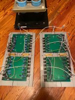
I'm from Russia. And since 2014 I own Pass Lab X350.5. I bought it from an authorized dealer in St. Petersburg. It was a show piece that I auditioned before purchasing. All these years he only made me happy. Recently, the sound began to disappear in the right channel after 20 minutes of warming up. After a light Siberian strike, everything returned to normal. But today it stopped working altogether. I decided to open it and saw a very sad picture, it turns out that it had already been repaired by someone ... But I bought it new!
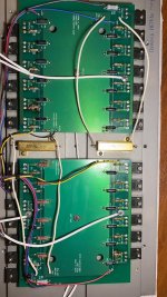
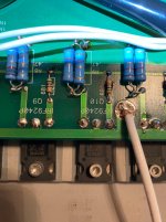
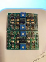
The resistors on the power boards are twisted, they are not in denominations, in several places under the resistors the board even burned out. In general, I decided to replace these Chinese resistors with good ones. Stopped at Mills mra 05 and Audio Note Tantalum Non magnetic. Now I have collected all this, but I do not know how to configure it correctly. I see descender resistors in several places labeled 5k p4-p7 bias; DIFF; OFFSET; P1 500. Please tell me how I can make the correct amplifier settings step by step.
I'm from Russia. And since 2014 I own Pass Lab X350.5. I bought it from an authorized dealer in St. Petersburg. It was a show piece that I auditioned before purchasing. All these years he only made me happy. Recently, the sound began to disappear in the right channel after 20 minutes of warming up. After a light Siberian strike, everything returned to normal. But today it stopped working altogether. I decided to open it and saw a very sad picture, it turns out that it had already been repaired by someone ... But I bought it new!
The resistors on the power boards are twisted, they are not in denominations, in several places under the resistors the board even burned out. In general, I decided to replace these Chinese resistors with good ones. Stopped at Mills mra 05 and Audio Note Tantalum Non magnetic. Now I have collected all this, but I do not know how to configure it correctly. I see descender resistors in several places labeled 5k p4-p7 bias; DIFF; OFFSET; P1 500. Please tell me how I can make the correct amplifier settings step by step.
Attachments
-
 WhatsApp Image 2021-04-27 at 19.16.19 (1).jpeg219.3 KB · Views: 891
 -
 WhatsApp Image 2021-04-27 at 19.16.20.jpeg135 KB · Views: 475
 -
 WhatsApp Image 2021-04-27 at 19.13.52.jpeg212.6 KB · Views: 447
 -
 WhatsApp Image 2021-04-27 at 19.13.51 (1).jpeg221.2 KB · Views: 496
 -
 WhatsApp Image 2021-04-27 at 19.13.49.jpeg145 KB · Views: 451
 -
 WhatsApp Image 2021-04-27 at 19.04.16.jpeg173.4 KB · Views: 712
 -
 WhatsApp Image 2021-04-27 at 19.13.50 (1).jpeg164.5 KB · Views: 673
 -
 WhatsApp Image 2021-04-27 at 19.16.20 (1).jpeg168.8 KB · Views: 650
 -
 WhatsApp Image 2021-04-27 at 19.16.19.jpeg155.5 KB · Views: 689
read this for start: Pass Labs X150.5 , checking/adjusting offsets ,Iq and gain – Zen Mod Blog
when you're sure that you know how to arrange voltmeters for setting procedure, write here and I'll try to guide you
when you're sure that you know how to arrange voltmeters for setting procedure, write here and I'll try to guide you
Hello everyone! Thank you very much for your answers, they helped me a lot! After replacing all the resistors, I began to make adjustments. After reading the forum, I found a similar topic about X150.5. I ended up needing me UGS4 modules. I have a working amplifier 150.5 and I took these modules from it and all the Diff and Ofset parameters are normal on my X350.5.
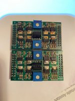
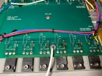
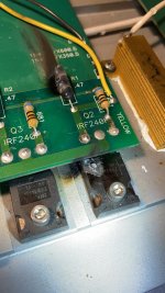
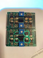
For the final thermal adjustment, I decided to cover the lid, but then a disaster struck. Crocodiles have closed the Bias point. now I need to change the resistors and transistors on 1 channel again. If everything is clear with resistors and diodes, then not with transistors. These IRFP240 and IRFP9240 most likely need to be selected according to certain parameters. Please tell me how to do it right? Which manufacturer do you need to take transistors? And I also cannot identify the elements on the UGS4 module in the middle, can you tell me what is installed there?
For the final thermal adjustment, I decided to cover the lid, but then a disaster struck. Crocodiles have closed the Bias point. now I need to change the resistors and transistors on 1 channel again. If everything is clear with resistors and diodes, then not with transistors. These IRFP240 and IRFP9240 most likely need to be selected according to certain parameters. Please tell me how to do it right? Which manufacturer do you need to take transistors? And I also cannot identify the elements on the UGS4 module in the middle, can you tell me what is installed there?
Attachments
the central 7 legged thingies are 2sk389 and 2sj109 double JFET sorry about that, recently I contacted PASS guys for a similar problem with a semi-fried friend X150 Amp and the guy told me I "could" use the UGS6 board (the only that is currently produced) to replace the old board, the old boards (I suspect the jfets toasted) had a big offset that worsened with heat and never settled (I attempted to adjust it with the lid closed and with shorted inputs and also changed all trimpots once, just managed to diminish the the effect, but it was always there) then did a bit of research and they may not be fully equivalent or may need tweaking, none the less the guy stopped responding my emails and never validated me that theory, just throwed the towell on that amplifier already and never tried the new board in place
I
These are bjts for cascodes if I remember correctly . Btw, what happened to this UGS board, it looks like someone with not much experience messed with it, fuzzy solder points, all soaked in flux..?
Also look at places for R1 and R2, R14.. There are 3 resistors soldered parallel, what's up with that?
I can't define these elements either, can anyone tell me?
These are bjts for cascodes if I remember correctly . Btw, what happened to this UGS board, it looks like someone with not much experience messed with it, fuzzy solder points, all soaked in flux..?
Also look at places for R1 and R2, R14.. There are 3 resistors soldered parallel, what's up with that?
Last edited:
Hello everyone! Thank you very much for your answers, they helped me a lot! After replacing all the resistors, I began to make adjustments. After reading the forum, I found a similar topic about X150.5. I ended up needing me UGS4 modules. I have a working amplifier 150.5 and I took these modules from it and all the Diff and Ofset parameters are normal on my X350.5.
For the final thermal adjustment, I decided to cover the lid, but then a disaster struck. Crocodiles have closed the Bias point. now I need to change the resistors and transistors on 1 channel again. If everything is clear with resistors and diodes, then not with transistors. These IRFP240 and IRFP9240 most likely need to be selected according to certain parameters. Please tell me how to do it right? Which manufacturer do you need to take transistors? And I also cannot identify the elements on the UGS4 module in the middle, can you tell me what is installed there?
middle - 2SK389BL (positive rail), 2SJ109BL (negative rail); hard to find genuine and expensive as night with Pro; you can replace them easily with 2 x 2SK170BL and 2 x 2SJ74BL, matched pairs ; easiest to get LSK170/LSJ74 B matched quad here at Store : Linear Systems Matched JFETs – diyAudio Store
second ring in UGS4 are BCP56N as positive cascodes and BCP53P as negative cascodes, no need for matching
outer ring are ZVP2110 mosfets in positive rail, ZVN2110 mosfets in negative rail; match them as pairs if you can (matched pair up, matched pair down)
UGS modules are easy to repair, cost being another thing; though, these amps are valuable , so no biggie
ask if you have more to ask ....... but I believe that you have all necessary info (regarding settings) in my blog
Hello everyone, especially Zen Mod !!!
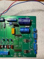
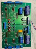
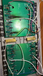
I have successfully repaired the power boards, replaced transistors and resistors. Everything works correctly with small boards from X150.
I have read the article many times on the Bias and Offset settings, but in my opinion, the correct settings have not been achieved.
When setting the voltage Bias 125 mV indicated on the power board, I get very strong heating. In this regard, the question is: how to correctly adjust bias not only according to the temperature of the radiator, but using a control measuring device - a multimeter + oscilloscope, etc.
Question two - please say how to match transistors Zvp and Zvn for small boards.
I am not sure why you did not contact Pass Alan’s directly ?
Obviously someone messed around with it and it ended up being less reliable. These amplifiers are not know to break down ever!
If you email Pass Labs they will most likely provide you guidance on setting up the amplifier.
Obviously someone messed around with it and it ended up being less reliable. These amplifiers are not know to break down ever!
If you email Pass Labs they will most likely provide you guidance on setting up the amplifier.
They are unlikely to enlighten you. I also wrote to them for details about the correct bias value for X250.5, but they replied that I must be guided by the current consumed from the socket and by the temperature of the radiators. They didn't even give me a range of approximate bias values. I am also looking for more concrete information related to the bias value for X250.5.
I have been the the factory several times and they will fix any failure.
Email. Explain the problem. Sometimes they will ask for a board or module to be returned.
I’ve done that for a customers First Amp that oddly failed for an unknown reason and was involved in the repair with Nelson himself.
They are not going to give you a schematic.
I don’t get all the hubbub
Email. Explain the problem. Sometimes they will ask for a board or module to be returned.
I’ve done that for a customers First Amp that oddly failed for an unknown reason and was involved in the repair with Nelson himself.
They are not going to give you a schematic.
I don’t get all the hubbub

this is similar enough:They are unlikely to enlighten you. I also wrote to them for details about the correct bias value for X250.5, but they replied that I must be guided by the current consumed from the socket and by the temperature of the radiators. They didn't even give me a range of approximate bias values. I am also looking for more concrete information related to the bias value for X250.5.
https://www.zenmod.in.rs/pass-labs-x150-5-checkingadjusting-offsets-iq-and-gain/
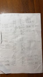
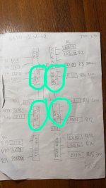
Indeed, at x150.5 the procedure must be very similar, but x250.5 does not have test pins. The bias voltage drop measurements are made on the 0.47 ohm resistors, but I don't know which one, because in this amplifier not all transistors have the same bias current. Half of them have lower bias. So, I ask those who know exactly the X250.5 model, to tell me which are the 0.47 ohm resistors that I need to measure. Does it matter if I adjust the DC offset before or after the bias? I am attaching the measurement sheet made by me. Thank you very much.
Attachments
All the hubbub is due to the fact that I live in Romania (Europe), and in this wonderful country we do not have a service authorized by Pass Labs. We have enough skilled craftsmen, but they only troubleshoot the product, they do not have the specific information necessary for the correct adjustment, to bring the amplifier to the optimal parameters that Mr. Nelson Pass thought. This is where my hubbub comes from, because I have to manage it myself, I can't send it for service in another country. I hope I am better understood now. Thanks a lot.I have been the the factory several times and they will fix any failure.
Email. Explain the problem. Sometimes they will ask for a board or module to be returned.
I’ve done that for a customers First Amp that oddly failed for an unknown reason and was involved in the repair with Nelson himself.
They are not going to give you a schematic.
I don’t get all the hubbub
XA350.5, facts:
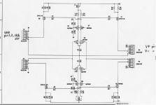
(- means for both OS halves - temporary lift one leg of 2SA1943 base resistor, short B and E, so these are moved out of current distribution; when everything else is done, connect them again as from factory)
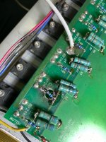
- all mosfets are having same value source resistor - 0R47
-all mosfets must show same/close voltage sag (meaning same/close Iq) across source resistors, be it N channel or P channel
if that is not the case, mosfets are not matched or resistors are damaged; what is more likely, who knows - without exactly knowing history of amp....
so, this amp deserves some love ........ to solve it with least amount of trouble, one need to go full monty - obtaining all matched mosfets and new source resistors
that would be two sextets of matched IRFP240, and two sextets of matched IRFP9240, all that per channel
practically - if you buy 100+100pcs, you'll get them easily and have plenty of matched ones for later ........ or just sell them
then sole criteria for final value of Iq can be heatsink temperature ( counting on 50C in summer)
again - if you see 0R47 resistor - all of them must have equal voltage sag across
equal means - 10% bracket, practically
(- means for both OS halves - temporary lift one leg of 2SA1943 base resistor, short B and E, so these are moved out of current distribution; when everything else is done, connect them again as from factory)
- all mosfets are having same value source resistor - 0R47
-all mosfets must show same/close voltage sag (meaning same/close Iq) across source resistors, be it N channel or P channel
if that is not the case, mosfets are not matched or resistors are damaged; what is more likely, who knows - without exactly knowing history of amp....
so, this amp deserves some love ........ to solve it with least amount of trouble, one need to go full monty - obtaining all matched mosfets and new source resistors
that would be two sextets of matched IRFP240, and two sextets of matched IRFP9240, all that per channel
practically - if you buy 100+100pcs, you'll get them easily and have plenty of matched ones for later ........ or just sell them
then sole criteria for final value of Iq can be heatsink temperature ( counting on 50C in summer)
again - if you see 0R47 resistor - all of them must have equal voltage sag across
equal means - 10% bracket, practically
- Home
- Amplifiers
- Pass Labs
- PassLabs X350.5 repair and adjustment