Safety concerns about a particular crossover design

Hello everyone,

I’m revisiting an old crossover design of mine which I consider a potential threat to my amplifier (or any amplifier for that matter). I hope some more experienced people with knowledge of electronics and how electrical networks work to help me better understand and define the impact of such design.

To cut the long story short, it’s all about the current going through the coil of the HP filter (see the first picture below). Due to relatively high value of the capacitor in series with the tweeter (10uF) as well as the small value of the coil in parallel (0.17 mH), it seems that the latter is effectively shunting huge amount of current to ground. At least, that’s my assumption and in order to establish exactly how much current I’m dealing with, I’ve ran a simulation using XSim (luckily I kept the ZMA files of the project). The XSim screenshot below (second picture) shows that the current through the coil reaches as high as 3.85 Amps at around 3 KHz when using 100W power / 8 ohms. This number alone doesn’t tell me much if not compared to some sort of a threshold. Here the Ohm's law comes in handy and according to my calculations a 100 watt amplifier on 8 ohms load is expected to deliver 3.53 Amps of current.

Obviously there’s an excessive amount of current going through that coil and all I want is to keep it at bay. I’am well aware of the possible solutions like lowering the cap value, increasing the inductance of the coil and so on. The small value of the resistor before the cap is not helping either. But attempting new crossover design is something I’d like to avoid for a number of reasons. That’s why I decided to mitigate the problem with a simple solution by using a resistor in parallel with the tweeter, which I soldered directly to its connectors. The value of 22 ohms seems reasonable for that purpose and now the current trough the coil is down to 3.52 Amps (see picture 3) which is exactly on the threshold. There’s a tradeoff as well - now the tweeter response is down with around 2 dB, but I don’t mind it. Actually, I think it’s even better that way.

Finally, I’ve measured the impedance of the speaker (picture 4) and you can see that its lowest point is around 3.8 Ohms at around 180 Hz which is also a reason for concern.

My question is whether the speakers with this final crossover pose a significant risk to an amplifier. Is the small adjustment with the resistor in parallel enough to effectively alleviate the problem and bring the current to more reasonable (not harmful) level.

I hope my calculations are correct and I’m not missing something along the way.

I’d very much appreciate your input 🙂

-Allex

Attachments

  • 0D9E7C41-9986-4416-A3C5-A7B4BFF1D6B0.jpeg
    0D9E7C41-9986-4416-A3C5-A7B4BFF1D6B0.jpeg
    17.4 KB · Views: 129
  • 78F1AC32-5F1A-44EC-9889-56BC2F3B55E5.jpeg
    78F1AC32-5F1A-44EC-9889-56BC2F3B55E5.jpeg
    184.7 KB · Views: 118
  • 3C9537B4-C5FF-43DF-B2D5-04CED8BCD4EE.jpeg
    3C9537B4-C5FF-43DF-B2D5-04CED8BCD4EE.jpeg
    186.9 KB · Views: 117
  • 72BD7DC1-D413-4D26-8C3E-143B9BF3443D.jpeg
    72BD7DC1-D413-4D26-8C3E-143B9BF3443D.jpeg
    64.2 KB · Views: 128

Novar base list?

Working with manufacturer to repop 9 pin PtoP and PCB Novar bases. What's in question is (as always w/ manufacturing) potential sales. Anyone know of online database that compiles tubes by base style?
Alternate plan is to go thru my B&K 707 tube tester chart & compile list of tubes that test on Novar socket, but this will only cover mainly North American tubes, and miss some of the Euro and / or Russia makes. I'm hoping to find worldwide database.
Jim

Mullard Stereophonic Amp LTSpice Model

The only way to get better at LTSpice is keep practicing and probing; these models will never get built. Sometimes, things don't work out, as in this case: I am getting 9μV output, clearly something isn't right. 😆

My brain is soggy due to being unwell, maybe missed something, can someone have a quick look over the schematics and see if missed something, please?

Here is the original schematic: http://www.r-type.org/articles/art-003f.htm.

Thanks in advance! 😀

Attachments

PSB Stratus Gold & Goldi PORT DIMENSIONS & Specs

Does anyone have DETAILED dimensions of the port that is on the early '90's PSB Stratus Gold as well as the mid-'90's PSB Stratus Goldi speakers? I have an interest in modding the earlier model to the latter model. I have not verified (yet) whether internal cabinet volume had been changed between the two. Any related info would be greatly appreciated.
PSB Stratus Gold vs Goldi.jpg

Troubleshooting blown GK amp; 120hz + voltage on output

Trying to troubleshoot this GK amp (schematic attached).

Found three blown transistors (Q2, Q3,Q7) and replaced them. All other transistors seem to test good. Replaced the filter capacitors.

When the amp is powered on, it produced a loud hum at 120hz. There is 48v DC voltage on the speaker output. This would indicate blown power transistors (Q4 & Q8) right? I had a replacement for Q8 and put that in (no change) and Q4 also tests good.

What else can this be, given the voltage on the speaker out? I ordered a replacement for Q4 but don't expect it to work since the incumbent tests good.

Attachments

Require ALPS 50KAX2 Potentiometer for Sony WALKMAN D6C

I have been restoring my Walkman D6C that i picked up at local vintage store.
However to my bad luck the record level pot is broken and only one channel is working.
Rest i restored it to full working condition.
Sony part number: 1-230-275-11
This pot was custom made by ALPS for Sony D6C.
I saw the eBay ads for RK16 50KAX2 but as per datasheet it wouldn't fit the PCB. Any leads as to anyone who has older stock of sony spare parts/repair enthusiasts.
Any input regarding this is greatly appreciated
Thanks in advance.

Attachments

  • WhatsApp Image 2021-04-21 at 10.32.33 PM.jpeg
    WhatsApp Image 2021-04-21 at 10.32.33 PM.jpeg
    63.2 KB · Views: 257

How do you assess & test the result for your DIY passive filters on the speaker?

Are finetuning my MTM passive xover in the current room and in the actual baffle.
The midranges are Audax HM210Z10 in about 16 liter each and the tweeter is a Mundorf AMT29CM1.1
Xover-points are around 340 and 1900 hz ( have active filter for woofers under 340 hz)

Have made 2 different xovers with slightly different values on both coils and capacitors, & both with & without resistors.
I think it´s so hard to judge the result when you listening in mono, and old amps often have "balance-button" so you can go from right to left easy but mine haven´t.
So i have to connect one MTM at the time, and go to the speaker and disconnect and connect the other to shift.....Not good!

And feels that it makes it more difficult because my MTM works from 340 hz.


I'm hoping for some advice on two aspects of this process.
The first is simply this: What do you listen for when you've put together a new DIY passive xover?

For example, do you listen to the speakers separately or together?
And how are you looking for ways to refine the result?

With woofers connected or not?
In "sweetspot-sofa" or right in front of the speaker?
Have you a favorite curve, and how does it look like ?

For an exemple i post a pic on the 2 different passive xovers mesaurements (that i listening on), but so hard to analyze/judge the sound i think

Best regards John/Sweden

Attachments

  • L and R MTM 1 Mars.jpg
    L and R MTM 1 Mars.jpg
    224.6 KB · Views: 137

For Sale Normundss input and switch boards for the dam1021 dac module

Hi dear diyaudio friends

For sale is a set of Normundss input and switch boards for the dam1021 dac module. In another thread I'm also selling DAM1021 modules.

The input and switch boards are brand new and partly assembled by Normund.

The set includes:
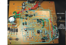
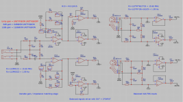
DAM1021 assembled input board V2.3
DAM1021 input board balanced connectors
DAM1021 assembled switch board V2.3
DAM1021 assembled muting and output board V1.1
DAM1021 muting board balanced parts
Raspberry Pi 2/B+ connector for DAM1021 input board

I will only sell the complete set.

Price is 100€

I’m also willing to trade for one or more of the following items:
(Of course, I will pay difference in value)

Manufacturer sealed bags of:
2SJ74-BL
2SK170-GR
2SJ74-GR
2SK370-BL
And maybe other rare signal JFETS or dual JFETS

BurrBrown PCM1704-K DAC chips

Analog Devices MAT02 and MAT03 dual monolithic transistors

2 x Starkrimson® Ultra Amp Module

XRK Audio RTR TPA3255 Reference Class D amplifier

Please also take a look at my other offers in the Swap Meet


Here are some different shipping rates:
They may differ a little from country to country, for a exact quote for your country please ask.
Of course, I will charge only the prices I will have to pay)

(Prices for bubble wrap envelopes are valid for most countries worldwide, DHL package prices are a bit cheaper within Europe)

Bubble wrap envelope up to 500 grams (Deutsche Post):
Without insurance and tracking: 3.70 Euro
With insurance up to 30 Euro and tracking: 7.20 Euro

Bubble wrap envelope up to 1KG (Deutsche Post):
Without insurance and tracking (Deutsche Post): 7 Euro
With insurance up to 30 Euro and tracking: 10.50 Euro

Small DHL package worldwide (up to 2KG):
Without insurance and tracking: 10.99 Euro
With insurance up to 50 Euro and tracking: 14.99 Euro

Small DHL package within Europe (up to 2KG):
Without insurance and tracking: 5.99 Euro
With insurance up to 50 Euro and tracking: 8.49 Euro

Shipping within Germany will be cheaper, please ask.

I will ship anywhere in the world. Shipping costs strongly depend on the number of capacitors you are going to buy and which shipping method you prefer. Of course, I will only charge the real costs, I won't charge anything for packing materials and effort. I prefer to use Deutsche Post/DHL, but you can decide which shipper and which shipping method (letter, registered letter, small package, normal package, insurance, tracking) I should use.

As payment method I prefer PayPal for friends and family, so no extra fees will be added. Of course personal collection of capacitors in Cologne and payment in cash is also possible.

Kind Regards

Phil
IMG_1020.JPEG

InterM R500 Plus locked on prot. mode

Hi!

I've got an InterM R500 Plus amplifier which shorted due to condensation and now I'm trying to troubleshoot and fix it. The protection leds are on, channel 1 signal led is on and both clip leds are on. There is no sound.
First things first - I have only a very limited idea of what I'm doing so hoping for sincere help. I am very interested in fixing the amplifier, not because it's so worth it, but because that's my way of learning.

There were 4 resistors burned out when I opened the amp, on the output board (R501-504). So that was the obvious problem. But after changing the resistors, the problem remains.
I've measured the DC offset - channel 1 it's 69.5V, channel 2 it's around 10mV. I also measured the output of the amplifier board on channel 1 and it's the same.

Where to go from here? What and how should I measure?

Thanks!

Attachments

suggestions for simple headphone amp (OPA1688 / 1622)

Hello everyone, I need to design a very low noise headphone amplifier with the following characteristics:
headphones: Vic Firth Sih2 datasheet
Sound pressure level 102db +/- 3 db (1mw at 1kHZ)
maximum power 100mw
Impedance 32 ohms +/- 15%

Conditions:
  1. The circuit is powered by a single 9V battery.
  2. Candidate ICs: OPA1688 or OPA1622 (I read suggestions)
  3. the input of the amplifier will be connected to an AD9833 (Programmable Waveform Generator IC) datasheet

my questions are:
can these ICs work with a single supply (9V Battery) ?
Can they reach the maximum power of the headphones? I need to at least reach 110db SPL


I have already tried with different ICs, (TDA2822, TDA7052, PAM8403) but the result is very noisy, mainly white noise and RF noise in some occasions.

I have a EARS Headphone test jig from miniDSP, to do the tests and measurements Link

I really appreciate your comments and suggestions.
Thanks

Leonardo

For Sale Best Soviet audiophile tube rectifires and double triodes

I offer the following items
VO-188 ( = RGN2004 ВО-188) Soviet Audiophile Rare Rectifier Tubes / years 1950s / UNUSED/ 12pcs 45 usd/ea
5C3S ( = 5U4G 5ц3с) BLACK PLATE ANOD Soviet Audiophile Rectifier tube /years 1960-1961/ UNUSED/ 6pcs 35 usd/ea
6N9S (6Н9С) = 6SL7 = 1579 MELZ Metal Base Soviet Audiophile Double Triode /UNUSED/ 2pcs 50 usd/ea
6N8S (6Н8С) = 6SN7 =1578=ECC32 MELZ Holed Anodes Audiophile Double Triode / UNUSED/ 2pcs 150usd/ea
6N8S (6Н8С) = 6SN7 =1578=ECC32 MELZ Smooth Anodes Audiophile Double Triode / UNUSED/ 2pcs 100usd/ea

Getting some fancy bluetooth headphones.

My daughter is sending me a Senheiser over ear headset.
Its supposed to support aptx support. And all the latests bluetooth codecs. How would I test or quantify the improvements in bluetooth. As in what tests would I have to run. What data to collect. Im in the process of testing as many china modules as I can. Some are really good some not so good. Right now I measure the freq response to see if its flat. If its not I measure the response curve.
I also look to see if sine wave at various freq comes thru undistorted. What other tests can one do ?. Id like to test the improvements in Aptx and Ver 5. Then make a call if its worth paying extra for these modules to use in my builds.

How does Tangband measure Xmax?

I was thinking of buying a pair of Tang Band W5-1138SMF to use as midbass drivers for my desktop speakers.

They claim 9,25mm of xmax, but nowhere does it say if it is one-way or two-way or by 70%Bl or by 50%BL.

Does anybody know how they measure it?

I also found Omnes audio SW 5.01 that looks similar but has one way Xmax of 7mm, which is either more or less depending on Tang Bands way of measuring.

Defective Definitive Prosub 100TL

Hi all,

I discovered, during the week, that one of my Definitive Subs had stopped working. I rarely use them unless I'm watching DVDs these days, so the fact one had stopped working, wasn't recognised. I have 2 such subs and I use them as 'stands' for my Paradigm studio 40s in a 'quasi' home theatre setup.
I have opened up the sub and done a few rudimentary tests:
  1. The 'Auto on/off' light continues to glow whether or not there is any input signal (it's supposed to turn the internal amp off in the absence of any sound)
  2. I measured the resistance of the 10 inch subwoofer and it's at around 40 Meg Ohm...
So it looks like the speaker is history (it looks pristine, no visible damage).
On the main PCB there are a pair of circa 3W resistors that become very hot when the AC power is applied. 2 adjacent resistors (1/2W) show signs of overheating as does the junction between the 3W resistors.

Unfortunately in SA we have had 'load shedding' periods for years where we have/don't have power. These have become extreme over the last year or so with only circa 16 hours electricity available over the course of a day. The timing of these 'outages' varies from day to day (as they are 'rotated') so switching electronics on and off when the power is expected to go off/turn on, is not a sensible approach. Thus these subs have remained on and have been subjected to the power availability (there's a large 'thump' when power is restored - at least when the sub is working).
  • So the question arises as to whether to; purchase a new driver and carefully check/repair the electronics
  • Scrap the lot and buy a new subwoofer
  • Build a new active subwoofer and use the existing sub chassis/box (I have a 'spare' stereo 50W amp I could use as a driver in bridge mode I guess).
  • Build a passive subwoofer together with an analogue crossover and volume control, using the existing chassis/box
P.S. I'm more 'into' music than I am to surround sound.

Suggestions, pros/cons, appreciated.
Thanks

For Sale DIY Audio Chassis components....300mm baseplate and a few riser panels

SOLD

Asking $15 plus shipping


I have a few chassis components for Deluxe or Dissipante type chassis that maybe someone can use.

1- 260 360mm baseplate for 300mm deep chassis, unused with mounting screws

1- 210 x 180 mm riser plate, unused

1 - 150 x 120mm riser plate, unused

1- 180 x 150mm riser with holes drilled, slight bends.

1- small 150 x 30 mm riser segment, used

1- bag of left over mounting screws, bolts and nuts for chassis kits, over 1 pound.

Shipping weight will be about 8 pounds and I will make up a container about 18 x 14 x 2 inches to hold it all.

IMG_1755.JPGIMG_1756.JPGIMG_1757.JPGIMG_1758.JPGIMG_1760.JPG

Anyone have a copy of sheets for K&K Cascode kits?

Hi all. I ran across these unused kits I had got from Kevin years ago, and realized any instructions that came with are long gone. I'm sure I could figure it out eventually, but I figured it was worth a shot seeing if anyone on here still had whatever data/instructions he sent with them. I've got a few of the smaller "Cascode", and a few of the larger "Large Cascode" boards.

Thanks for your time,

Loren

Crossover and time delay/offset, for horns particularly.

Crossovers for cone/dome drivers on flat(ish) baffles are pretty well understood.
Typically the physical layout issue is that the tweeter is a little too far forward on a flat baffle.
The tweeter can be physically moved back or a little time delay added to it in the crossover, especially convenient with a DSP crossover.
All well documented.

But almost the opposite issue occurs when horn mid/tweeters (assumed 2 way for simplicity) are used with cone woofers - the depth of the horn means the mid is delayed.
It is possible to push the horn driver forward to the woofer plane but this can be problematic - physically awkward with a substantial horn and a potential source of diffraction problems for the woofer.
It is possible to delay the woofer but this seems to miss an opportunity.
The delay of the mid would seem to allow a closer approach to a linear phase crossover but without any DSP step.
I have seen little analysis of this, there was a thread a while back but the OP seems to have lost interest.
"Quasi-optimal" crossover for high-efficiency loudspeaker system.

I read the Vanderkooy & Lipshitz articles referenced in the 1st post that supposedly prove the idea is unworkable.
A closer study shows that certain assumptions in their analysis are too restrictive, a practical solution may be possible after all.
It will require asymmetric crossovers for the HP and LP, and probably non standard shapes.
I have found the maths a little difficult, presumably why V & L only looked at the simple symmetric case.
Anyone have any references or ideas on this?

I will start with an example.
Since we have a time delay an obvious candidate for the Low Pass would be a Bessel filter.
First is a Bessel LP, it has maximally flat Delay.
Second is a HP "Bessel" created by the usual method, the frequency response is mirrored.
But a Bessel is not about frequency response so this does not create a HP with maximally flat delay, as is obvious in the plot.
A closer match would be a HP filter with maximally flat delay.
Anyone know what this is called or have a reference so I don't have to create it from scratch?

David

Attachments

  • Bessel_HP.png
    Bessel_HP.png
    30.9 KB · Views: 752
  • Bessel_LP.png
    Bessel_LP.png
    30 KB · Views: 745

Lower than normal impedance in vintage speakers

Hi,
I got a pair of vintage full range speakers. I haven't tested them sonic-wise as I want to build cabinets first to have a thorough evaluation of the sound.

The units are visually in good conditions, but the Ohm meter reads 5.2÷5.3, while they are rated for 8 Ohm.

Shall I expect any quality degradation from this lower impedance?

Thanks,
gm

What to do with Beyma 12P80ND drivers

Having had a pair of 12P80nds gathering dust for the last 6 years - i have been pondering do i use them or sell them. I saw this speaker over the weekend which got me thinking
https://www.abacus-electronics.de/produkte/aktivlautsprecher/oscara/oscara-212.html. I have a pair of TPLs , the 12P80nds and some seas subwoofer drivers all spare that could be used. The challenge with AMTs has been integrating them with other drivers. The 12P80nd was meant to be a good match, but i didn't like it when i tried them in a simple box a while back. So could the answer be trying a different box....... I know some will shout out dipole, however if you use the TPL's open baffle, they are bipole not dipole and you get some horrible interactions, from my experience mixing dipole and bipole.. So i was thinking monopole upto a 1000hz and then bipole or hornloaded TPL's above that with higher DI, if needed

So how to best use the 12P80nd... well i was thinking a terminated transmission line - so will effectively get a infinite baffle response. I modelled a logarithmic spiral as a first pass, not the most efficient use of cabinet space. Am i right in assuming that as the driver will only be covering frequency's up to 1.5k smoothing out features smaller than a wave length wont add much. I have the CNC so can make what ever shape of transmission path i like.
spiralhorn (2).png

To manage the beaming of the 12" drivers i was thinking of trying something like this first to see if it works that well I have some 12mm Perspex to make a test waveguide.
.
waveguide.JPG

Need opinions and help on modifications

Hey guys need your help I have a little Dot MK 2 headphone /preamp. What I want to do is I'm going to take it out and put it in a different case I don't like the chassis that it's in.

Since I'm taking it apart what I want to know is based on the photo are there any audio upgrades I could do to this film capacitors coupling capacitors something like that you guys think would make a sonic difference in the amp?

Attachments

  • 0314231933_HDR.jpg
    0314231933_HDR.jpg
    489.8 KB · Views: 126

Altec 802 Trade

Looking to trade a fine sounding/looking Altec 802D driver that reads around 6.2 ohms DCR for a Altec 802C or 802B driver
that reads over 8 ohms. Will consider buying an 802D under 7 ohms DCR.

Attachments

  • Altec 802D 4.JPG
    Altec 802D 4.JPG
    119.7 KB · Views: 70
  • altec 802D 5.JPG
    altec 802D 5.JPG
    90.7 KB · Views: 77
  • Altec 802D 3.JPG
    Altec 802D 3.JPG
    146.6 KB · Views: 79
  • Altec 802D 6.2.JPG
    Altec 802D 6.2.JPG
    226.2 KB · Views: 78

For Sale DX25+WG300, Tectonic BMR, Peerless Woofers

I'm looking to offload all my current drivers I have and hop out of the DIY space. It's been fun, I've learned a lot, but it's turned into a frustrating money pit of unfinished . I understand I am not a frequent user here so if anyone needs verification I have a reverb account with a perfect seller rating and lots of sales. Just ask and I'll shoot you the link.


DX25+WG300 - $40 shipped.

330477866_752593789336802_4030851346781494914_n.jpg


Tectonic BMR TEBM46C20N - Just cover shipping.

330220138_846303499803693_134574597598289015_n.jpg


Peerless 160f25 woofers

330146403_1665788760508034_1780557179121313029_n.jpg

Programming QCC3034 BT AMP circuit

Hi guys, i put this question in here because of this good thread CSR8675 programming guide w. software and tons of CSR info and have in the past edited a few CSR chips, but prefer the QCC3003/3005 boards. Normally ill use my CSR\USB programmer and connect to the board with a Pogo Pin clamp and then change the name of the BT and edit the DSP\EQ settings. Recently i grabbed the QCC3034 board shown in the Aliexpress link
Screenshot 2022-12-18 190847.png

but cannot figure out what the N, P, P, V and G relates to the programmer and if i can use the Unviersal front end and APK tools like you do with the others?

Screenshot 2022-10-22 141350.png


Screenshot 2022-12-18 191318.png


I would really like some assistance if available as this amp seems to have 8watts per 4 ohm driver where my other QCC3003/5 boards only have 5 (onced boosted to 6.5v)


Attachments

  • Screenshot 2022-12-18 190841.png
    Screenshot 2022-12-18 190841.png
    127.7 KB · Views: 183

Retirement project

Now that I have more time, I decided to produce this amplifier.
Laid out the P.C.B and made them myself.at home.
I still need to fabricate. a couple of heatsinks for the bridge and the driver transistors.
When I have done this, I will wire everything into a temporary case and test.
Looking forward to this so far it has been very satisfying to return to the audio hobby.

Attachments

  • 20230225_160138.jpg
    20230225_160138.jpg
    530.4 KB · Views: 262
  • 20230225_160159.jpg
    20230225_160159.jpg
    480 KB · Views: 252
  • 20230302_104820.jpg
    20230302_104820.jpg
    556.4 KB · Views: 261

Technics SU-A900MK2 overloaded/amp not working/nothing burnt

Hi!

few years ago my son unfortunately overloaded Technics SU-A900MK2 amp, full volume on 2x 100W 4ohm speakers... This exact device was in 2 service shops and both told that it has faulty AMP and it's not worth it repairing so they put their hands away from it.

AMP "does not amplify", it just leaves the sound that comes into the AMP

I haven't seen any burnt transistor, shorted capacitor or burnt route on the PCBs, relays do turn on so the protection is fine
the 2 power modules - SVI3205B + RSN6000B seems also fine, zener diodes checked with multimeter, nothing weird 🙁

RSN6000B does have a power transistors which can be purchased from link below - 2SJ338 + 2SK2162
https://www.ebay.com/itm/192202054620
17.2V rail does provide 17V
Q751 + Q752 are quite hot -- they wobble so the solder is melting


I will try reflowing the PCBs, desoldering the transistors and checking them.. in best scenario I wish hopefully the transistors inside the RSN6000B are faulty and nothing else 😀

Does anyone had a similar issue with Technics AMP ?

Schematics included in the attachment


Thanks a lot for your thoughts!

Attachments

  • IMG_20220303_213925.jpg
    IMG_20220303_213925.jpg
    728 KB · Views: 1,153
  • IMG_20220303_213954.jpg
    IMG_20220303_213954.jpg
    440.8 KB · Views: 556
  • technics_su-a900mk2_sm_1.pdf
    technics_su-a900mk2_sm_1.pdf
    1.8 MB · Views: 1,024

How to use subwoofer apart from speaker? Logitech X-230

I have a Logitech X-230 system, I don't want to use the X-230 sound system speakers because my laptop speakers are of better quality, I just want to use the Subwoofer. But the problem occurs here. Because using the subwoofer system to use with its own speakers. So it doesn't work alone. I drew the program of the system. More or less, if my hand holds a soldering iron and a tool, it can be seen if it can be explained. I did not cancel these speakers. I want to connect the subwoofer to the laptop and use it only as bass, how can I see it or is it possible? I am sending the subwoofer's circuit and system diagram attached.
Forgive me if my english is bad because i am not a british or american citizen 🙁....

Attachments

  • Ekran görüntüsü 2023-03-17 185648.png
    Ekran görüntüsü 2023-03-17 185648.png
    452.6 KB · Views: 1,073
  • Adsız.png
    Adsız.png
    13.5 KB · Views: 1,515

Can I use this power supply for both +/-15v and 9v?

I need to power circuits that use different voltages at the same time, +/-15v for a stompbox adapter circuit, and +9v for several guitar pedals, and led dB meters. Can I use this power supply splitter with a voltage divider in parallel after the +15v to get +9v, and then wire grounds together? Also, how much current should the 30v dc wall wart be rated for to power everything?

Attachments

Pass Labs X5 Buzz/Hum

This is my first post, so please be gentle. I’ve got a beautiful Pass Labs X5 that is the backbone of a mixed use Stereo/HT setup. The stereo side drives two channels from an Adcom GFP-750 and the HT side uses the other three channels for my front soundstage being driven by an Onkyo RZ50. I love the aesthetics and sound of the amp, and plan to gift it to my son as an heirloom.

The problem is, it audibly buzzes, and that same buzz comes through the speakers if you get within a foot or so of the speakers, and it’s driving me insane.

I recently had a friend and very competent tech go over the amp, and replaced the main filter caps as a possible solution. We also used some dampening material to try and isolate the toroidal transformer from the case. Neither of those things made a difference.

At this point, I’m wondering if there’s anything that can be done? New transformer potentially?

147BE268-F8E4-45C2-A211-4B909A6F8416.jpeg

B1995AA6-1D4C-4AE1-BF2C-42AE1A758D27.jpeg

Hoping a community member, or Mr. Pass himself will be able to assist.

Thanks.

Armstrong 625 diagnosis

Hi all you Armstrong fans. I've acquired an Armstrong 625 with no sign of life and am in the early stages of repairing it. Would really appreciate some guidance on diagnosing the fault(s) and the following symptoms:

I have replaced the main reservoir cap and the 2 DC speaker caps. I now have power, lights on the dash;
I get audio from both L & R speakers 1 and 2, plus each side on headphones.
However - audio is ONLY with TAPE input, and this is low/moderate output volume (even with the Volume turned up to full);
No output from AUX or DISC inputs, and no TUNER output from the onboard receiver;
The output from the tape input continues regardless of how the Selector is set - ie selecting another input makes no difference and the output from the tape continues unaltered;
The backlight on the Tuner dial and Armstrong light illuminates, but the receiver does not seem to pick up an FM signal, and the red stereo light never illuminates. I've tried attaching antennas to each socket.
When playing a signal through TAPE, Treble and Bass dials don't affect the sound, nor does applying High and Low filters.
All the solder connections look and feel sound, and no previous repairs have been done. I needed to replace the original large caps, as above.

My thoughts in summary are that while the PSU and Amp seems to be working on both channels, it seems that the Inputs are not being selected and connected properly to the Amp (A17). However this does not explain why the receiver seems unresponsive - this may be a separate issue.

Any thoughts on where I should look and poke next, please? Many thanks in advance!

LED Mounting

I'm planning on mounting 3 X 5mm LEDs in a panel utilizing the recommended mounting fixtures shown. However the LEDs have a shoulder around the base preventing sliding the LED into the barrel and the strut inside the mounting barrel prevents sliding the LED into the barrel from the back.
I could trim off the shoulder of the LED if that won't compromise the LED or try and trim/grind out the strut inside the barrel. What would be the best course of action?
The website for Newark seem to indicate the mounting barrel is compatible with those LEDs.
PXL_20230316_230959524.jpg

Lundahl strap change

Has anyone noticed how a couple of years ago Lundahl changed from a ferrous to non-ferrous strap. Personally without science to back me up I always thought the ferrous strap not a good idea. Lundahl must have thought so too. I'm assuming they must have had a reason. Anyone know why they did it? I don't recall it ever being mentioned anywhere. Or perhaps any other anecdotes on shrouds etc.

New:
2785C-768x706.jpg

Old:
PXL_20230303_101415270.MP.jpg

Please help me decide what to build

I have a stash of wonderful wood that is suitable for building speakers or fine furniture. I have so many tools like saws (including table saw), jigs I only used once, a hardly used router and bits, etc. plus a motivated helper. It seems wrong not to build a speaker.

My goal is to build small speakers that are suitable for use with or without a subwoofer. My emphasis is on clear midrange, high output, and low distortion.

I'm looking at two drivers right now. Feel free to make another suggestion. I love this driver on paper, been itching to use it for years. https://www.parts-express.com/FaitalPRO-6FE100-6-Professional-Woofer-8-Ohm-294-1150?quantity=1 Also this driver https://www.parts-express.com/FaitalPRO-5FE100-5-Professional-Woofer-8-Ohm-294-1140?quantity=1

Using this calculator https://www.diyaudioandvideo.com/Calculator/SpeakerBoxEnclosure/ the first driver returns a vented box volume of 1.3 cubic feet. That's bigger than my 8" two-ways. I suspect if I build this it will be a wonderful speaker, studio monitor quality, but maybe too big.

This is where my limited experience takes me. Would it be worthwhile to "cheat" and configure a smaller box? The 5" midwoofers would probably fit the bill just fine (crossed @ 100 Hz) but the 6" drivers seem (on paper) to offer so much more, so fudging might be a good strategy - and this is where I need advice.

I'll look at other drivers etc (not too expensive) or advice on alternative strategies (passive radiator etc). Thank you!

Windows 10 media streaming issue

Hi there, I have been playing with Windows 10 built-in media streaming service. My music files are in the shared Music folder on the Windows 10 PC. Another Windows PC on the same home network can play those files without any issue. For the playback I use Windows Media Player on the other PC.
The issue is that my music does not play back on an Android phone, using BubbleUPnP. I can see the Windows 10 machine as UPnP/DLNA library, but can't see the contents of the Music media share.
For comparison, I have a NAS with shared music folder, and I can play back all music on Windows or Android from there without any issue.
Why am I unable to browse and play music files from a Windows 10 using a smartphone?

PA amplifier question about hookup

Greetings,

we have a pyramid brand PA amplifier with auto mic talkover which we use at our factory. We moved to a new facility and upgraded to a bigger wattage unit, but it started making a horrific noise.

Anyhow, I put the old PA amp in place, and it works fine but it is not very loud because the wattage is significantly lower. I had tried to buy a replacement with the larger wattage but they were very expensive at the time and hard to find. I ordered one from the internet and they sent the wrong item etc.

Anyhow, long story short, and simply put - Can I run the output from the functioning amplifier with auto talkover into a less fancy but higher wattage amplifier to maintain functionality but increase our volume?

We are using 70v style speakers with it. The way its rigged up is our phone system has an optional adaptor that you can connect to speakers and call an extension to page out, so when we moved i sprung to get sirius xm radio for the shop and some nice speakers with the intention of dual purpose of paging and entertainment

SV S1616D Build Questions

First, thanks go to Victor for getting the kit to me so quickly. Your customer service is always top notch.

When I first got the kit, I thought I bit off more than I could chew. But I have gone slowly. Despite that, I caught at least two wiring mistakes during final review and sorted them out prior to applying power.

I have powered it up and nothing has exploded or caught on fire. So far so good.

I am posting my voltages below. As you can see, most everything looks within range. One of my concerns is that I have roughly about a 15% imbalance between the two 12au7s.

Is this a concern? If so, where do I start to try and track it down.

I haven’t tried any music yet to see if it actually works yet. I’d like to sort out the above prior to buttoning it up.

Attachments

  • 5227C0E6-C749-43EA-AFFE-342BF10F1391.jpeg
    5227C0E6-C749-43EA-AFFE-342BF10F1391.jpeg
    480.4 KB · Views: 141
  • B77672CA-C9B6-4BD5-B41C-3040734802BA.jpeg
    B77672CA-C9B6-4BD5-B41C-3040734802BA.jpeg
    626.3 KB · Views: 150

Looking to repair a Feiler TS-9 Electronic Vacuum tube Volt-Ohm-Milliammeter

Evidentially it was offered in a factory wired form or kit form. I would like to find/buy the kit instructions and or schematic for this unit. I can't seem to find a schematic or any information other than it was made in 1950 was offered wired for $48 and in kit form for $22. Its quite nice for its age and with some rewiring and tweeking the 4 pots I would be able to bring it back to its former glory or at least good enough so I can use it on circuits in old radios and such. Any help would be appreciated. More than willing to buy the information that I need.
PC310003.JPG
PC310004.JPG

For Sale SB Acoustic DIY speakers

For sale my DIY speakers that I own for more than 6 years. Cabinets were made then, but I upgraded with SB Acoustics drivers about two years ago. Match made in heaven.

Drivers are: SB Acoustics SB15CAC30-4 midbass, SB Acoustics Satori TW29B berilium tweeter and SB Acoustics passive radiator.

Dimensions: 200 x 305 x 315mm. Veneer is American walnut 2.5mm thick. Front is Corian (Solid surface).

Crossover is LR2 with Jantzen Superior capacitors and Jantzen WAX foil inductors. They are 4ohm with 88dB sensitivity.

Selling them with FBM Rondo speaker stands.

I spent about 2000€ on them when I purchased everything and for the enclosures. Selling for 1100€.

Time to move on to different projects with bigger drivers and 95+dB sensitivity.

Location Croatia!

Regards

Attachments

  • 1.jpg
    1.jpg
    140.2 KB · Views: 204
  • 2.jpg
    2.jpg
    128.1 KB · Views: 189
  • 3.jpg
    3.jpg
    93.9 KB · Views: 178
  • 4.jpg
    4.jpg
    161.8 KB · Views: 184
  • 5.jpg
    5.jpg
    183.7 KB · Views: 200

Visaton B200 - foldable Open baffle try

Hi there !
I got a pair of Visaton B200 for my first try in building speakers. They will be powered by a tube amp 2x8watts : Elekit-Tu 8200.
My room is 20 x 23 feet (more or less) and 7,5 feet in height (with wooden beams on the ceiling)

I want the panels to be foldable, for obvious reasons.

This idea is coming from french internet site exploring accoustic : https://www.petoindominique.fr/php/plandesign.php
and has been realized by Christian . Size is about 3 feet high and 4 feet wide.
This one'a got two drivers but my will is to keep an only full-range driver

My first question is about the phase plug on B200 : where can i get it ? is it DIY ?
Second question : Dominique (see link above) says full range drivers absolutely need a correction in the medium curve and he propose to add a resistance (between 3 et 30 Ohms) , a self ( between 0.5 et 2.5 mH) and a capacitor (1 , 5 or 10 uF). Did anyone made any measurement with the B200 ?


front view.png
folded.png
folded .png

CSS SDX10 versus Seas L26RO4 in a ~1 cu ft sealed enclosed with dsp- swarm (4 sub system) ?

I have looked into drivers for a 4 sub swarm-like dba system and have come across these two drivers as high quality options. I am looking for mid 20Hz to ~80Hz performance band. I plan to use dsp crossovers, correction, etc. to pair these with 1 AE dipole 18 in an h frame per side from 80Hz to roughly 300Hz, then ribbons above. Which of these drivers would you choose and why? Thanks...

Looking for a McIntosh 4100 FM left channel integrated chip - IC702

I have a McIntosh 4100 receiver that works perfectly except for one thing. When in tuner mode, in stereo, the left channel doesn't work. I consulted with a national McIntosh expert and he suggested the IC chip for the left channel was bad. The chip number is IC702 with McIntosh part number 133-037. Does anyone out there have or know where I could acquire this part, to fix the minor FM problem? I'm not a technician, but if I could get the IC, I'd bring it to someone.

Unbalanced RCA to balanced converter buffer with variable gain adjustment schematic - can I add signals like that?

Schematics is attached.

I am wondering if I can add two signals coming from RCA inputs and XLR inputs? Will something like what I have makes sense to do in order to support both unbalanced and balanced inputs? I am trying to avoid to switch them with the manual switch.

First stage allows for gain adjustment.
Bias resistors R3, R4 were selected at 10K to set input impedance. Feedback resistors can be 15K or 47K and determine R3 and R4 values as 15K||47K = 11.3K and 15K||15K = 7.5K.

Second stage is balanced signals driver.
Unity buffer for the positive swing signal. Inverting unity gain opamp for the negative swing signal with bias resistor = 2K||2K = 1K. Current sharing resistors of 100R at each end to adjust for offset differences. Output signal doubles in value which is what I want. For example Topping DACs have 2Vrms output level for RCA outs. I will need to double that to drive my next stage at the amplifier end.

Balanced input stage is two impedance matching buffers to be able to drive the next stage at the amplifier end wich has input impedance of 1K.

I am assuming that connecting both RCA and XLR inputs at the same time and play music at both sources will add those two signals together and I will hear both sources?

Each opamp has decoupling capacitors, but those are at different sheet for schematics.

Any suggestions will be appreciated.

Attachments

  • sch.png
    sch.png
    65.1 KB · Views: 178

Best way to wire up 4 individual subs to a VTV nc1200 amp?

I want to use these 4 independent subs in a swarm like distributed bass array with dirac bass control dsp. I am told the dirac dsp will only work with mono subs so I am wondering how to connect the 4 subs to the VTV nc1200 stereo amp. This amp has one channel inverted to avoid power supply pumping. Can I bridge the nc1200 and simply run a wire from the + on one channel to each sub and a wire from the - of the other channel to each individual sub? The subs are 4ohm each and the nc1200 can handle 2ohm loads unbridged so 4ohms should be ok- if I put 2 sets in series, then those two sets in parallel, I should have a 4 ohm total load. Is this the way to go? Thanks.

Raspberry Pi and AK4399 and Amanero

Hi All,

Returning after years and having forgotten most of what I knew! I was running the originl Raspberry Pi with a Hifiberry Dac hat. I have kept this going with sellotape and sheer will power for too long. I've given in and purchased a Raspberry Pi 4. I have not bought a Dac hat for it (Yet)

I would like to see if I can repurpose another project - A chinese AK4399 based Dac that had an Amanero board connected via I2S for USB input from a Linux PC

I have no PC now and would like to run Volumio on my Pi 4 as music source. My question is -

How will I connect raspberry Pi4 to my AK4399? Directly by I2S or via USB and Amanero? I have some parts lying around to make a smooth 5V supply and intend to place the Pi in the box with the Dac as shown in pic. Any suggestions welcome!
Dac.jpg

Test Tunes for Subjective Evaluation of Drivers and Loudspeakers, Part 1 (Audio Xpress)

https://audioxpress.com/article/test-tunes-for-subjective-evaluation-of-drivers-and-loudspeakers

Here's a list of some test track choices, some known, some unknown, with links to Tidal and Qobuz playlists. One of the tracks was recorded in 1906!

But, fear not, there's also a hi-res recent recording of the same song.

There are three more installments in the works.

all my best,

john

Marantz NR1501 no sound

Hello.
Marantz NR1501 home cinema reciver.
This is a known issue with these amps. No sound from any source. There is sound when SOURCE DIRECT turned on.
I tried to solder capacitor 1000 uf 16v on IC1005..IC1006 as advised in many forums but it does not help me.
Can someone tell me how I can close some kind of circuit on HDMI board so that the sound is always there, but it would be possible to adjust the tone. When SOURCE DIRECT turned on, the tone is not adjustable.
I want use this Amplifier on my work just for AUX stereo and FM radio.

No service manual .....

Thanks

Anything inherently wrong with my bookshelf design?

E9FB4EF7-B773-4C26-9373-B492D8877E01.jpeg


3897F9AE-06FD-4D8E-8E44-95F34306DE74.jpeg


We’re settled into our new townhome to the point where I’m able to focus on buttoning up my center/bass unit and bookshelf projects the bookshelf being the focus of the thread of course.
These bookshelves are only intended to hit 90db maximum in case it’s pointed out that these won’t be loud.

I think I want to put a lot of emphasis on wide directivity to achieve a wide soundstage even if it sacrifices focus. In my best efforts to design a very wide dispersion speaker set I went with a .23cf Denovo knock down, Anarchy 554, Peerless TC5FC07-04 (1.5”), and Dayton ND16-6 (5/8”). I believe in my small living room a 5.5” long throw woofer is going to be just fine, and an overall compact form factor was a design goal.

The power will come from a set of dsp amplifier boards and the woofers will be sealed and have a moderate high shelf filter applied to flatten the response, at the expense of blistering midbass output. I think I will have a realistically flat response to around 35hz at ~85 maybe ~90db with about 100rms to each anarchy.

I included a picture of my living room just in case I might not want very wide dispersion there for whatever reason.

Cheers

Annealed Aluminum

I've posted a LOT of threads about Unity horns. To me, Unity horns are a fun puzzle to solve:

1) They can offer bandwidth that's comparable, or better than beryllium compression drivers

2) If planned carefully, they can cost 25% as much

As time wears on, I've definitely considered just "biting the bullet" and purchasing beryllium tweeters. Sure, they're expensive, but they DO perform really nice.

For the past couple weeks, I've been trying to make a phase plug for an aluminum tweeter, with little success. Frustrated with my project, I decided to buy an aluminum compression driver.

As I see it, aluminum is an attractive material for compression drivers because it's nearly as light as beryllium. Aluminum is 46% heavier than beryllium. Titanium is 243% heavier than beryllium. Titanium is popular in prosound tweeters because it's durable; aluminum is popular in hifi tweeters because it sounds better (arguably.)

AFAIK, Radian is the only manufacturer who makes aluminum compression drivers.

The obvious solution would be to purchase a set of Radian 475PBs. These are the same tweeters that John Sheerin used in the very first DIY Unity horn, and they seem to be very nice.

But I am cheap.

As I understand it, Renkus Heinz and Radian have some common lineage with Emilar. So I went looking on line for Emilar or RH drivers that are affordable. I came across the Renkus Heinz 1801. It's an old an unloved compression driver, doesn't seem to get a lot of attention online.

I bought a pair and measured them on their 'stock' horn. The results were not great.

Then I put them on a modern horn, the B52 clone of QSC's waveguide, the same waveguide from the Econowave Deluxe.

And I got this:

6usUjSu.png


If you ask me, this is really good performance. Especially for $80. I've included my EQ settings, and you can see they're basic. With a bit of tweaking, I think you could make this combo play 700hz to 18000hz, +/- 2dB. And that's almost as good as beryllium.

If you saw these compression drivers, you wouldn't believe it. They look like something made in someone's garage. Not a handsome driver.

TLDR: Is there something special about heat treated aluminum? These Renkus Heinz tweeters seem to perform nearly as well as beryllium, at 15% of the cost.

Attachments

  • 2020-11-23 11_32_10-Original Renkus-Heinz SSD-1801 1_ horn drivers - bad! _ #347950380.png
    2020-11-23 11_32_10-Original Renkus-Heinz SSD-1801 1_ horn drivers - bad! _ #347950380.png
    518.3 KB · Views: 552
  • 2020-11-23 11_31_54-Original Renkus-Heinz SSD-1801 1_ horn drivers - bad! _ #347950380.png
    2020-11-23 11_31_54-Original Renkus-Heinz SSD-1801 1_ horn drivers - bad! _ #347950380.png
    495.4 KB · Views: 584
  • Like
Reactions: EarlK

GSG Marty cube and MBM - Winisd simulation

Hi All,

I tried to estimate volume of Marty Cube subwoofer and simulated in Winisd.
Driver is 18" Lavoce SAF184.03.

The following are the problems I observed.

1. I am getting 112 dB at 22Hz, and 124dB at 100Hz.
So basically 22Hz is 12 dB lower compared to 100Hz.
So 22Hz is below F10 point. Is this ok??
GSG audio is claiming 115dB @ 22hz.

2. For 19Hz tuning, winisd suggesting 67" long port. But looking at the pictures, GSG port length seems to be around 41" long.

Am I missing something?
Please see the attached images for volume estimation and results.

Attachments

  • marty cube4.JPG
    marty cube4.JPG
    53.1 KB · Views: 863
  • marty cube1.JPG
    marty cube1.JPG
    80.2 KB · Views: 374
  • marty cube2.JPG
    marty cube2.JPG
    72.5 KB · Views: 311
  • marty cube3.JPG
    marty cube3.JPG
    82.8 KB · Views: 386

Does a car amp care about a noisy PSU

Hi Thanks for reading.
So my sold my old car but kept my beloved amp, and am using it at home powered by a simple power supply that i built consisting of a transformer+ rectifier+smoothing capacitors. Looking at the car amp, it is taking the 12 volts from the car battery and converting it into +/- 35 volts.
Does the amp care about the 12 volts psu if it is clean, or can it be noisy. Would lowering the power supply noise improve sound quality

Moving the goal posts.

Just had the pleasure of an update to Visual Studio Community.
My programs stopped working.
Narrowed it down to a bad registry read.
I was getting back a null string instead of "c:\" which points to drive software was installed on.

After a lot of internet trawling I found that 32 bit and 64 bit programs read the registry differently.
So I adjusted my code accordingly and it started to work.

I then had problems publishing my code to an output directory.
On some of the modules I was getting publish errors.
Everything looked fine and had previously worked.
I had installed some new anti virus software since I last worked on these programs so out of desperation I turned it off and the programs now publish correctly.

Taken me a good few hours work to do what should have taken half an hour.

Restek Fantasy II playing up a bit

Before I start I’m making you aware that I’m no electronics engineer, I can use a soldering iron to replace caps etc but other than that I have no fault finding skills.
So the amp works flawlessly when I’m using line 1 inputs ( my node ) but when using line 2 and now I’ve noticed line 3 the left channel is lower than the right until I turn it up and then it’s fine , could this be the source selector switch ( my Yamaha ca2010 did the same until I cleaned the switch)
Trouble is that the source selector switch on the Restek isn’t like anything I’ve seen before ( no little box if you get my meaning)
I’ve started recapping the amp for good measure, working my way from the back to the front ( I found 1 bloated cap ) .
Is this issue something obvious to you clever lot ?

C2F9114C-4A4E-431A-9DE5-03ADE3B3F267.jpeg
A83F25BA-C79F-495C-9CEB-0362E966F77D.jpeg

Arcam Alpha 7 CD (disconnected) causing hum

I have an Arcam Alpha 7 SE CD player paired with Arcam Alpha 6 amp, Beolab 6000 speakers and a Rega P3 (quite a mix!)

The CD player, even when not connected to the amp through RCA cables, is causing a hum through the speakers. Only stops when I unplug it from the mains power.

I took it to a hi fi shop when I bought the Rega and connecting it to their system was fine. No hum. Suggests there isn’t a fault with the CD player.

Any ideas? Thanks!

For Sale LND150N3-G N-channel Depletion Mosfet

I have around 150 pieces LND150N3-G N-channel Depletion Mosfets , they are bought from Mouser. Offers are welcome. Prices does not include PayPal and shipping costs. Worldwide buyers are welcome. Shipping from Finland or Germany. PayPal is accepted, the buyer pays the additional PayPal fees of 5%. The shipping costs may vary depending on the country. For the LND150N3-G the Factory Lead Time is 64 Weeks. Registered shipping to USA from Finland nearly 30US.

Sold out.

Attachments

  • IMG_20230313_050638.jpg
    IMG_20230313_050638.jpg
    174.1 KB · Views: 75

For Sale LM336Z 5 & LM336Z 2.5 Reference Zener diodes

I have around 180 pieces mostly the 5V ref , they are original Fairchild and National Semiconductor LM336Z_5 & LM336Z_2.5 reference Zener diodes. Offers are welcome. Prices does not include PayPal and shipping costs.
Worldwide buyers are welcome. Shipping from Finland or Germany. PayPal is accepted, the buyer pays the additional PayPal fees of 5%. The shipping costs may vary depending on the country.

Attachments

  • IMG_20230313_052210.jpg
    IMG_20230313_052210.jpg
    266.4 KB · Views: 52
  • IMG_20230313_052215.jpg
    IMG_20230313_052215.jpg
    215.5 KB · Views: 48
  • IMG_20230313_052217.jpg
    IMG_20230313_052217.jpg
    240.3 KB · Views: 47
  • IMG_20230313_052219.jpg
    IMG_20230313_052219.jpg
    243.3 KB · Views: 52

SWTPC Tiger 207/A bias adjustment

After repairing a SWTPC Tiger .01 (207/A) from the 70's I want to set the bias correctly. I have a copy of the assembly manual and have attached a copy of the schematic and also the bias adjust procedure. However, I question whether the bias procedure is correct. First of all it says that bias current should be set to 40 millivolts. I think they meant to say 40 milliamps. But even if this is what was meant it goes on to say to adjust for 15 mV between test points M and N. Wouldn't that product an idling current of 19.23 mA? If 40mA is the goal, wouldn't the voltage between M & N have to be adjusted to 31.2 mV? Or am I wrong? Thanks for any advice.

Attachments

  • Tiger 207A.jpg
    Tiger 207A.jpg
    726.6 KB · Views: 460
  • Bias adjust.jpg
    Bias adjust.jpg
    118 KB · Views: 379
Projects by fanatics, for fanatics
Get answers and advice for everyone wanting to learn the art of audio.
Join the Community
507,636
Members
7,881,511
Messages

Filter

Forum Statistics

Threads
405,924
Messages
7,881,511
Members
507,636
Latest member
tom.mccann