Hi all you Armstrong fans. I've acquired an Armstrong 625 with no sign of life and am in the early stages of repairing it. Would really appreciate some guidance on diagnosing the fault(s) and the following symptoms:
I have replaced the main reservoir cap and the 2 DC speaker caps. I now have power, lights on the dash;
I get audio from both L & R speakers 1 and 2, plus each side on headphones.
However - audio is ONLY with TAPE input, and this is low/moderate output volume (even with the Volume turned up to full);
No output from AUX or DISC inputs, and no TUNER output from the onboard receiver;
The output from the tape input continues regardless of how the Selector is set - ie selecting another input makes no difference and the output from the tape continues unaltered;
The backlight on the Tuner dial and Armstrong light illuminates, but the receiver does not seem to pick up an FM signal, and the red stereo light never illuminates. I've tried attaching antennas to each socket.
When playing a signal through TAPE, Treble and Bass dials don't affect the sound, nor does applying High and Low filters.
All the solder connections look and feel sound, and no previous repairs have been done. I needed to replace the original large caps, as above.
My thoughts in summary are that while the PSU and Amp seems to be working on both channels, it seems that the Inputs are not being selected and connected properly to the Amp (A17). However this does not explain why the receiver seems unresponsive - this may be a separate issue.
Any thoughts on where I should look and poke next, please? Many thanks in advance!
Checking all the supplies is the first step. The Armstrong uses a unique diode switching arrangement for input selection.
Is the 45 volt supply correct?
Is the 45 volt supply correct?
Provide us with a schematic/Service manual in order to track down the issue(s).
Otherwise, you'll only get numerous speculation from readers - going on endlessly and a waste of time.
And if you don't have a service manual/schematic, you're chance of success is highly limited.
Otherwise, you'll only get numerous speculation from readers - going on endlessly and a waste of time.
And if you don't have a service manual/schematic, you're chance of success is highly limited.
Thanks for fast reply, Mooly -Checking all the supplies is the first step. The Armstrong uses a unique diode switching arrangement for input selection.
Is the 45 volt supply correct?
I'm honestly not sure which pins on the Z20 PSU the 45V DC output comes from. I am in Uk so 240V mains supply - this is the same as the supply to the mains output. I also get:
58V AC between the b7 and b8 pins.
74V DC btw a2 (red) and both a3 (black) and a2 (pink) pins.
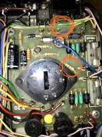
It is derived at the emitter of this transistor (hard to make out whether it says 628 or 625 as the reference). If the supply is missing then check the 160ma fuse and the series 47 ohm.

Sure: http://www.audiomisc.co.uk/Armstrong/600/600faq.html for a atart There are other diagrams for the 600 series on the web.Provide us with a schematic/Service manual in order to track down the issue(s).
Otherwise, you'll only get numerous speculation from readers - going on endlessly and a waste of time.
And if you don't have a service manual/schematic, you're chance of success is highly limited.
Ok, see photo for what I am measuring between - what I think is the transistor emitter and the 4.7kR. Result is 0V across them.It is derived at the emitter of this transistor (hard to make out whether it says 628 or 625 as the reference). If the supply is missing then check the 160ma fuse and the series 47 ohm.
View attachment 1049052
Attachments
Sure: http://www.audiomisc.co.uk/Armstrong/600/600faq.html for a atart There are other diagrams for the 600 series on the web.Provide us with a schematic/Service manual in order to track down the issue(s).
Otherwise, you'll only get numerous speculation from readers - going on endlessly and a waste of time.
And if you don't have a service manual/schematic, you're chance of success is highly limited.
One difficulty is that the component numbers on the circuit don't correspond to the marking on the PCBs.
...some progress (having re-read Mooly's earlier post more carefully). I now have 45V DC supply, having understood that the 47R is the black ERG resistor (which is fine) and the fuse was faulty (which looked ok visually but tested broken and now replaced).Sure: http://www.audiomisc.co.uk/Armstrong/600/600faq.html for a atart There are other diagrams for the 600 series on the web.
Ok, see photo for what I am measuring between - what I think is the transistor emitter and the 4.7kR. Result is 0V across them.
I now have a tuner playing fine at volume and in stereo. Great, and thanks Mooly for getting me this far.
However still the same issue with the Aux input not being recognised.
Further hints...? (will respond tomorrow)

...some progress (having re-read Mooly's earlier post more carefully). I now have 45V DC supply, having understood that the 47R is the black ERG resistor (which is fine) and the fuse was faulty (which looked ok visually but tested broken and now replaced).
I now have a tuner playing fine at volume and in stereo. Great, and thanks Mooly for getting me this far.
However still the same issue with the Aux input not being recognised.
Further hints...? (will respond tomorrow)
👍 excellent.
The input switching is very unusual on the Armstrong but checking the basics still apply. You need to check the appropriate DC voltages are present when Aux is selected.
The circuit shows around 21 volts at the two points arrowed and 12 volts on the top of the diode 522. You will only see those voltages when the switch is in the Aux position.

All working fine - confirmed voltages at indicated points, which change appropriately as the selector switch is moved.👍 excellent.
The input switching is very unusual on the Armstrong but checking the basics still apply. You need to check the appropriate DC voltages are present when Aux is selected.
The circuit shows around 21 volts at the two points arrowed and 12 volts on the top of the diode 522. You will only see those voltages when the switch is in the Aux position.
View attachment 1049192
All working fine -
As in just the voltages? or all working and with sound?
As in the voltages are as they should be. However the main symptom remains, i.e. Radio 3 works beautifully, but nothing from the Aux input.As in just the voltages? or all working and with sound?
For inputs I have a DIN-RCA adapter, as I don't have any other devices with DIN connectors. I've tried conntecting this to a DAC, and well as a line level output on a CD player. Neither work. One issue the user manual stresses is not to connect an earthed appliance to the DIN input, to avoid creating an earth loop. Both the above appliances are connected to the mains and earthed. There is no loud hum, but just mentioning in case this might be possible issue to eliminate but connecting to an ipod or similar.
Ground loops are something to look at if they are a problem, otherwise at this point don't worry about it.
The proper way to diagnose this would be to use a scope and trace the signal but I'm guessing (maybe wrongly 🙂) you haven't access to one. If you haven't then you need to trace with a meter (on low ohms range) continuity from the socket to the top end of that 2.2uF cap on the aux input.
At this point... it might be more likely to simply be a connection issue if you are using din leads and adapters. Just try linking the unused pins on the aux input din socket to the ones that are used to see if its just a a case of incorrect configuration.
Also with no inputs connected you could try selecting aux and then just touch each pin of the input socket in turn with a metal implement like a screwdriver and see if you hear any clicks or hum. Always begin with the volume on a low level doing that.
Will do. I'll poke around further later on. I don't have a scope but could probably borrow one.Ground loops are something to look at if they are a problem, otherwise at this point don't worry about it.
The proper way to diagnose this would be to use a scope and trace the signal but I'm guessing (maybe wrongly 🙂) you haven't access to one. If you haven't then you need to trace with a meter (on low ohms range) continuity from the socket to the top end of that 2.2uF cap on the aux input.
At this point... it might be more likely to simply be a connection issue if you are using din leads and adapters. Just try linking the unused pins on the aux input din socket to the ones that are used to see if its just a a case of incorrect configuration.
Also with no inputs connected you could try selecting aux and then just touch each pin of the input socket in turn with a metal implement like a screwdriver and see if you hear any clicks or hum. Always begin with the volume on a low level doing that.
Many thanks again for your support and advice Mooly - a fantastic and generous help and a good way for me to learn.
As Mooly suggest this may be nothing more than a bad connection and could even be the DIN socket/Board. I had exactly the same problem yesterday with the Aux input on a 621. On further investigation I lifted the input board and found several really quite bad dry joints around the DIN socket area. I hasten to add the problem was solved once I had resoldered the joints.
To solve AC problems I use a pocket radio as a signal generator. 1/8" stereo phone plug to dual RCA plug adapter is about $4. Turn the volume down to about 1/4 , they will put out about 7 vac and you wan't more like 2 vac. I use an Analog AC voltmeter with a 20 vac or 2 vac scale to detect the signal. These can be had as low as $30 new. A .047 uf (200 v up) capacitor series the negative lead keeps the pointer from reacting to DC.
If you tune to a rock station, the pointer will dance to the music about 2 beats per second. If you find instead a high steady signal, you've likely got an ultrasonic oscillation.
Used scopes are chock full of expired electrolytic caps. New $80 digital "scopes" typically have maximum voltage of 80. Scope probes are $40-50 and if you step on one, it is that much again. Pamona grabbers to banana plug cables are $7. My simpson 266XLPM meter is ~35 years old, has no electrolytic caps in it to expire. Has 2 vac scale.
$160 fluke RMS Digital voltmeters will see music, but they stop responding above 7 khz so ultrasonic oscillation is invisible. Also no pointer won't dance to music. Cheap DVM make random numbers on music not 50-60 hz, and average over 4 seconds so you miss bad solder joints that come & go quickly as you press the probe on them.
This is definitely my next line of enquiry. I can now get sound through the Tape DIN Input, although not nearly as loud as the TunerAs Mooly suggest this may be nothing more than a bad connection and could even be the DIN socket/Board. I had exactly the same problem yesterday with the Aux input on a 621. On further investigation I lifted the input board and found several really quite bad dry joints around the DIN socket area. I hasten to add the problem was solved once I had resoldered the joints.
Wow this thing is temperamental! I eased up the pre-amp circuit and lightly touched all the solder joints on the board, and given the pins on the DIN socket connectors a small addition of solder. I'm pretty sure the joints are all good now. The pins with attached wires tend to loosen and I had one de-laminating the circuit from the board, so need to be really careful with this. Anyway enough pre-amble.
Back to Mooly's comment above "Just try linking the unused pins on the aux input din socket to the ones that are used to see if its just a a case of incorrect configuration." The Phono/DIN adapter I got is connected to the Output rather than the Input - Doh. Elementary oversight. Rather than solder jumpers across the pins I am now looking for an adapter connected to the Input pins.
But... the tape input still does not work, and I have not tried the Disc/TT input.
The on/off switch sticks to on until I press it from the inside. Can these be cleaned and unstuck?
Probably next on the priorities to fix...as I start to turn up the volume I get an oscillating sound of around 3 or 4Hz. This does not occur when playing the tuner, which puts out considerable volume even when the vol control is 20% turned from zero. I tried attaching a sound recording of this behaviour to demonstrate but it appears audio files are not supported for uploading.
Different sources will likely have different output levels.
This is and has always been common to audio components.
This is and has always been common to audio components.
You need to quit waving the soldering iron around, delaminating boards, and trace the signal in to see where it disappears. With $50 of equipment described in post 16, or Mooly's suggested $500 of oscilloscope, 2 scope probes, a signal generator, cables & adapters.Probably next on the priorities to fix..
Bad switches, switching jacks, and potentiometers are the bane of 50 year old equipment. Not expensive to replace, if they are available. I believe Armstrong have plated on pcb fingers and edge connectors, which were abandoned about 1970 because they were such problems. Not enough contact force to exclude oxygen.
The oscillation is another problem, to be explored with tools above. The stage where it starts is where attention should be focussed, and not before.
- Home
- Amplifiers
- Solid State
- Armstrong 625 diagnosis