Good day,
Some months ago, I finished an OTL based on 17KV6 valves, which puts out 10W into 72R. It is based on Futtermann, +-150V Power supply and auto bias with 220R and circa 90mA idle per valve.
https://www.diyaudio.com/community/threads/beam-power-pentode-otl.391888/
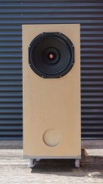
I also have a stash of 22JF6 which I want to use for a more powerful AB OTL amp to drive a 50R load (9x ~6R woofers in series). I want more power and less heat in the amplifier, so this time I decided to use fixed bias on the output tubes, but hat do double on the number of output valves, to get close to 50W into 50R.
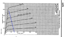
For 50W into 50R, I need 1A Rms, or 1.4A peak, which is 0.7A per valve. Furthermore, developing 50W over 50R requires 50VRMS at the output, or 140Vpp, or 70Vpeak from each valve. Using +-155V power supply (and circa 150V at G2), it means that each valve operates between 150V and ~90mA at idle, and 80V and 700mA at peak. The blue trace connects there two points, looks doable (and with that I mean the worst case for the valve, where the G1 is at 0V (same potential as cathode, so limit of class 1) and 150V at G2, the plate is able to go down to 80V and pass 700mA).
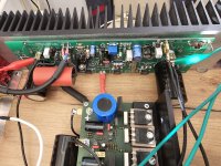
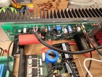
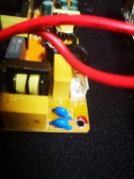
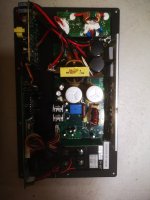
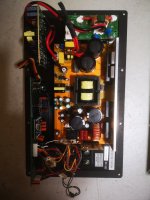
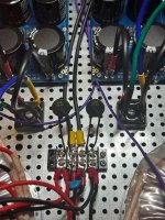
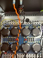
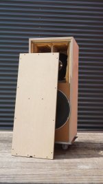
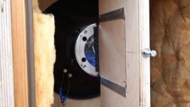
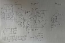
I built the amp, much like its smaller brother. I use a 500VA transformer with 2x 115V secondaries, that go into a diode bridge and CRCRC (1200uF per C, 3R per resistor) for the positive and negative rail. Output is about +-160VDC.
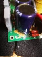
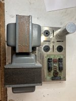
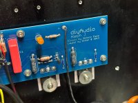
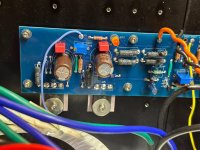
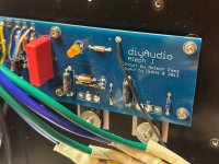
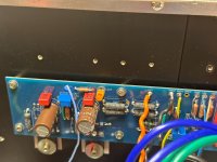
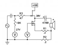
For the fixed bias I, for the moment, made three separate power supplies, A, B and C. I have a single transformer with 3x 27V AC secondaries, each fed into a bridge and filtered with 2x470uF, 20k and 390k bleeder. Close to the valve and the 130k grid leak I have 50uF local decoupling. These three supplies are completely independent from each other. Supply A is connected to the upper cathode of the 1st channel, Supply B is connected to B-, and provides bias for both channels, supply C is connected to the upper cathode of the 2nd channel. I feed the primary of this transformer with a VARIAC, to allow bias adjustment.
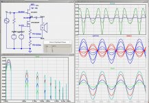
I built the amp (both channels) and let it run at idle, with al bias values at around -29V (in relation to the respective cathode). I apply 1kHz sinewave to the 1st channel and it starts clipping at circa 12W (measured 25V RMS into 50R). That means that each valve is only accomplishing 0.35A peak…
I measure around and finally put my DVMs across the bias supply A-A1, B-B1, and C-C1. All bias values where at -29V at idle, but when I start increasing the level, the value of bias A-A1 starts going up, at the 12W it is at -35V. The value at B-B1 goes to about -30V, the value at C-C1 (which has no signal applied, so still idle) stays at -29V. Why does that happen?
(20k and 390k filtering on the bias is a bit on the high side, I could well use 1k and 20k bleeder, current consumption of the bias would still be below 2mA.)
Looking at the scope it is clear that the top of the sine is clipped, implying that the top tube can’t pass more current, which is understandable at it is biased at -35V, while the lower is at -30V, with both getting the same signal from the concertina?
The driver (using a E180F) is fed from a separate 300V DC supply, the heaters are all fed from AC. At idle and up to 10W the amp is working very fine (I already got rid of oscillations, a different story…), only when requesting more power, it is somehow, I think, current constrained and altering the bias supply value.
I also thought about the resistance in series with G2 causing too high a drop, limiting voltage at G2, which is essential to pass more current – I will still measure that!
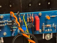
Originally, I had 10R resistors in each cathode to help equalize current over both valves. With peaks of 0.7A, these would develop 7V local feedback, so I (temporarily) bypassed them, but did not make a difference for the output power.
Many thanks for all of your comments and ideas!