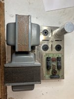
A couple of months ago I picked up a pair of over-priced derelict Dynaco MK-III tube amps.
They didn't have any rectifiers or power tubes, and one of them had a pretty well over-heated choke which had kakked its sealing wax all over the inside of the bottom cover.
So rather than trying to get them functional I decided to simply strip them down and start over. The power and output transformers were good, and that's really all I needed.
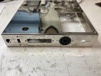
The chassis are both fairly pitted, and there isn't much that can be done about that, and a liberal application of metal polish didn't erase the pits, but these are not meant to be show pieces, they're meant to be working examples in my primary system.
My plan is as follows:
Modify the input circuit to get rid of the admittedly not-that-good-sounding 6AN8 input/phase splitter tube.
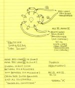
I settled on an elegant input circuit designed by Kara Chaffee and written up in an article in AudioXPress, March 2001.
It uses 1/2 of a 12AT7 (a tube I really like the sound of) as the input stage and a 6CG7 dual triode as a long-tailed pair phase splitter. It also has a clever variable feedback circuit.
Retain the tube rectification, which I think is important.
Remove the selenium stack and replace it with a modern diode.
Remove the can capacitor and replace it with a modern replacement circuit - I chose the design from Sheldon Stokes's "SDS" Cap Board having had positive experiences with it on previous Stereo-70 restorations.
Install modern ceramic tube sockets, and replace all the ancillaries - switch, speaker terminals, input jack, power cord - with new modern equivalents.
Remove the redundant wiring for powering a partnering preamp from the front panel socket but keep that socket for bias measurement.
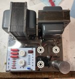
So step 1 is done - strip the chassis, remove all the tube sockets. This particular amp was factory built, and the sockets were riveted, so those had to be drilled out.
(photos of the "before" are not the amp in question - this clearly was not factory built, but is in very similar condition to its mate which is the stripped chassis)
Comments are welcome.
Attachments
I have 2 Mark III's that I built from kits back in the 1970's, that I used till the power supply capacitors blew out impressively in the 1980's. Been waiting for time to work on them since. Moved them house to house about 10 times. Now retired, and this will be an interesting and useful thread for me. Looking forward to your progress.
I'm not following you. What's the point of putting a series 1N4007 in line with each of the diode elements of the rectifier?Also add the "diode mod" to the rectifier tube socket.
Won't that introduce noise? What are you hoping to accomplish?
Recent 5AR4 tubes tend to arc more easily. The series diodes prevent that.
This technique has been around for quite a while.
This technique has been around for quite a while.
It will improve the reverse voltage ability AND reduce the reverse current to a level that does not permit ionization of gas remains in the tube.I'm not following you. What's the point of putting a series 1N4007 in line with each of the diode elements of the rectifier?
Won't that introduce noise? What are you hoping to accomplish?
I see what you're saying and the reasoning but I still don't get why I'd want to do it. Peak inverse plate voltage on a 5AR4 is 1.5kV, and that's more than double the output of the transformer. The maximum allowable reverse voltage for a 1N4007 is just 1kV . Plus, the diodes will rectify the signal ahead of the 5AR4. In fact, I've seen several mods to ST70 and MK II / MK IV amps that delete the tube rectifier completely replacing it with two 1N4007 diodes and a rudimentary delay relay circuit to protect the rest of the tubes. The SDS Labs Cap-board from Triode Electronics has such an option.
The diodes will defeat the purpose of the rectifier tube altogether, rendering it into simply a delay device so that the plates of the rest of the tubes in the circuit won't get full plate voltage immediately.
It's sort of like putting a tube buffer after a transistor amplification circuit. The transistor is still there...maybe smoothed a bit by the tube buffer, but it defeats the purpose of having the tube amp in the first place.
@baldrick
It just works.
The reason s that a rectifier tube always has some gas that could be ionized, and when pressed at it's limit som will
ionize (and therefore starts to lead current, a flash over has begun). The diode will both limit the reverse voltage and
if ionization has begun, limit the current to avoid a full flash-over.
It's not interesting what the peak reverse voltage of a rectifier tubes is if and when you have some ions in the tube.
And yes, one can replace with solid state BUT then comes for some amps like st70 higher then wanted voltages
on all caps in the B+ chain. Trying to fix that with delays will get inte another swamp, it will get into other problems.
The 1n4007 is an effective cheap and reliable solution.
I like the Chaffee mod a lot.
The only thing I'd add is a much bigger cap AFTER the choke, maybe 10x.
Regarding the rectifier, the good ones can still be found: I've got 2 Philips that I paid about $50 ea., not too long ago.
The only thing I'd add is a much bigger cap AFTER the choke, maybe 10x.
Regarding the rectifier, the good ones can still be found: I've got 2 Philips that I paid about $50 ea., not too long ago.
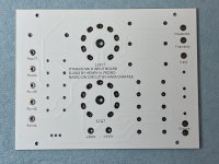
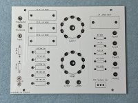
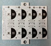
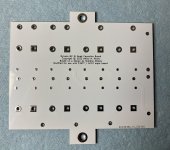
Some really nice looking PCBs arrived today.
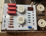
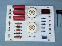
I mapped out the Chaffee circuit onto a new input board the same size and shape as the original.
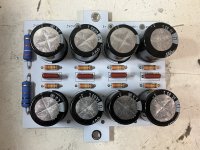
I also made up a Cap Board similar to Sheldon Stokes's one, but incorporating a couple of resistors that otherwise would have been floating so these boards are meant to be used together. Once the Cap Board arrives I'll post pics.
Once these are proven out and tested I will make any necessary changes (like the mounting holes which are too small) to the PCB layout , move my components over and then make them available to the community to buy if you want to make a quick and easy change to your own MkIII / MK IV.
Attachments
I see what you're saying and the reasoning but I still don't get why I'd want to do it. Peak inverse plate voltage on a 5AR4 is 1.5kV, and that's more than double the output of the transformer. The maximum allowable reverse voltage for a 1N4007 is just 1kV . Plus, the diodes will rectify the signal ahead of the 5AR4. In fact, I've seen several mods to ST70 and MK II / MK IV amps that delete the tube rectifier completely replacing it with two 1N4007 diodes and a rudimentary delay relay circuit to protect the rest of the tubes. The SDS Labs Cap-board from Triode Electronics has such an option.
The diodes will defeat the purpose of the rectifier tube altogether, rendering it into simply a delay device so that the plates of the rest of the tubes in the circuit won't get full plate voltage immediately.
It's sort of like putting a tube buffer after a transistor amplification circuit. The transistor is still there...maybe smoothed a bit by the tube buffer, but it defeats the purpose of having the tube amp in the first place.
The point is that very few, if any, modern 5AR4s will hold up well in this amp. A Mullard certainly will but even a selected Chinese or Russian 5AR4 just doesn't meet the original specs. Rather than change the whole supply, you add the diodes. It doesn't do any harm and it keeps both the slow warm-up and the original tone. There's absolutely nothing to loose by doing it and potentially much to gain when you avoid a flashover in the rectifier.
Further to including the 1N4007's is that if/when your rectifier tube ages and starts arcing, the mod may well save your power transformer from an overheated/stressed/failed \ht secondary winding. Also note that the ss diode does not change the diode 'on state' characteristic of the valve rectifier - it does not 'rectify' the voltage (per se) before the valve controls the on-voltage - it just acts as a redundant buck-up diode to avoid collateral damage to your power transformer, and also to allow any costly NOS tube to age gracefully without pre-maturely arcing.
It's been a few days since I last posted about this Mk III rebuild, but I've been waiting on parts and some have started arriving.
Because of its starting condition almost everything will be brand new, save for the transformers.
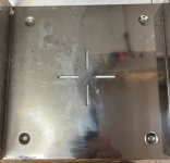
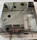
Interestingly, the factory built older of the two MK IIIs that I have used rivets to attach all the sockets, switch gear and binding posts. Also, very wisely there are plastic grommets in the holes for the transformer wiring. The kit-built MK III did not have any grommets, so I ordered some new ones from Digikey.
I also installed a new power switch - it has better specs than the original but is fully plastic bodied. I hope it will last.
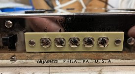
The speaker terminal strip was looking pretty ratty, too, but Digikey again to the rescue with a new FR4-based 5-screw terminal strip with the same dimensions as the old phenolic one. Some new slotted screws (6-32) make the look correct.
All new hardware was ordered to rebuild this - 8-32 screws and nuts for the transformers and choke, and 4-40 screws and nuts for the sockets and terminals. I also installed a new, isolated gold plated input jack to replace the old, tired and worn aluminum one that was mounted on a small phenolic board.
You can see in the photos where the old choke had overheated and stained the metal with wax and soot. Nothing I had in the way of cleaners or solvents could get it off, but a quick rubdown with metal polish (this stuff - I love it: Autosol Metal Polish Cream) did the trick - see the before and after photos of the chassis.
The screws, nuts and washers are all stainless and were from mcmaster.com
The switch, from Digikey: part# CKN10055-ND
The terminal strip, from Digikey: part # 36-4181-ND
The grommets, also Digikey: part # 3720-2073-ND
The choke is from Mercury Magnetics - a direct replacement for the original C354 choke. Bench measurements are pretty close! C354 Replacement
New tube sockets are ceramic types. Pretty generic. Decent quality. I bought mine from aliexpress a while back.
So the rebuild begins slowly.
Attachments
-
 Bottom Inside.jpg501.3 KB · Views: 168
 -
 Top w grommets.jpg495.5 KB · Views: 150
 -
 front new switch and binding posts.jpg374.1 KB · Views: 174
 -
 front binding post.jpg351.9 KB · Views: 157
 -
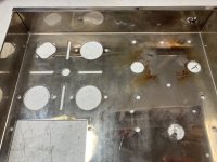 top inside with stains.jpg470.6 KB · Views: 148
 -
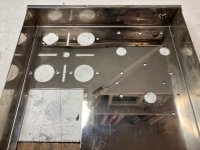 top inside clean.jpg475.8 KB · Views: 152
 -
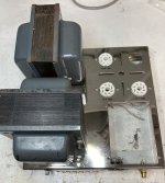 top new sockets.jpg455 KB · Views: 171
 -
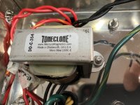 inside new choke.jpg370.6 KB · Views: 179
Built up the input board today.
I have to say that at first glance it looks amazing, but there are some fitment issues as can be seen in the photos.
Some interesting notes:
The semiconductor "shortage" is well extended to passive components as well.
Not long ago it was dead easy to get almost any resistor or capacitor of any value of any tolerance, but now it's getting tricky.
So much so that I had to compromise on R9 - the 18K resistor which was not available in 2W so I had to get a 3W one, and R8 was not available in 2W 1% so I had to get a 5% one.
Also, I could not single-source the parts either. There are a bunch from Digikey, but some others (especially the 2 watt resistors) I had to get from Mouser because Digikey didn't have them.
Also, I tried to find the best parts I could, which includes the 0.1uF WIMA coupling caps.
Kara Chaffee's article talks about re-using the 390 pF mica capacitor from the original circuit board, which I've done here, but she also suggests that increasing the feedback capacitor to 500 pF has good sonic benefits, so there is a 500 pF mica cap at the ready for testing later.
There is also some clearance issues with R9, RV1 (the variable feedback pot) and C1 at the top left. All are interfering with the chassis cutout.
Also, the "landscape" layout of the silkscreening is a bit odd next to the chassis silkscreening which is set at 90% to the markings on the PCB. I may change it to "portrait" mode later.
Also, in the future, I'll tighten up the parts placement so the board can be mounted from below like the original, but for now, and testing purposes, I've set them on some small standoffs (four nuts) and mounted it on top of the chassis. Doesn't look too bad and some aftermarket boards sit on top and look worse aesthetically.
Attachments
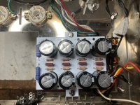
As opposed to the input board which had some fitment issues, the assembly and mounting of the capacitor board went rather smoothly.
The PCB accepted the Nichicon snap-in capacitors perfectly, and all the component placement is nice.
As I mentioned before, this board is loosely based on Sheldon Stokes's design as shown on his website https://www.quadesl.com/refurb/refurb_dynaMK3.html but with some modifications - removal of the 1N4007 diodes, and for convenience, the addition of two 5 watt resistors that are necessary for completing the Chaffee mods.
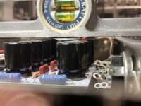
Mounting the board went perfectly on two 1/2" #8-32 standoffs which in turn hold down the output transformer.
As you can see, there's about 3/32" clearance to the bottom of the chassis, which couldn't have been more perfect.
The "ears" on the PCB are necessary to mount to the existing hardware and makes the board significantly smaller in order to clear wires from the transformers without interference.
I have almost everything I need now to complete the assembly and begin testing. Still waiting on the 5AR4 rectifiers and KT88 output tubes.
Attachments
I note that in the original circuit, the coupling capacitors are 0.1uF.
The Chaffee circuit uses 0.22 uF coupling capacitors.
Apart from the theoretical improvement in bass response, does anyone have any opinion on this matter?
The Chaffee circuit uses 0.22 uF coupling capacitors.
Apart from the theoretical improvement in bass response, does anyone have any opinion on this matter?
If you are talking about Dynaco MkIII coupling caps to the 6550 they are marked 0.25uF in the schematic
Loading 100k as per schematic give app. 6hz at -3dB
using 0.1uF will raise to 15hz, both are below your speaker ( i assume)
But as they are inside the NFB loop there is no difference in bass until the power is raised substantially.
Loading 100k as per schematic give app. 6hz at -3dB
using 0.1uF will raise to 15hz, both are below your speaker ( i assume)
But as they are inside the NFB loop there is no difference in bass until the power is raised substantially.
Your reply caused me to look again at another version of the schematic. It's funny - I read it at least a dozen times.
So it is .25 uF and I am going cross-eyed.
So it is .25 uF and I am going cross-eyed.
Unfortunately modern 5AR4 have a tendency to arc during warm up or during a momentary interruption of AC mains, if you turn on the amplifier again within a few seconds of turn off the rectifiers generally arc.I see what you're saying and the reasoning but I still don't get why I'd want to do it. Peak inverse plate voltage on a 5AR4 is 1.5kV, and that's more than double the output of the transformer. The maximum allowable reverse voltage for a 1N4007 is just 1kV . <snip>
When 5AR4 arc they generally develop a short between the cathode and one of the plates.
The 1N4007 prevent this from happening. I've been adding the series diodes since the early 1990s and it really helped to eliminate customer returns due to fried rectifier tubes. The 5AR4 performance is not otherwise impacted by the addition of the diodes in any way I have been able to measure.
- Home
- Amplifiers
- Tubes / Valves
- Chronicling a Dynaco MK III resto-mod


