I have experienced this, actually - an arc from the rectifier on a "hot" power up - that was, as you described "a momentary interruption of AC mains".Unfortunately modern 5AR4 have a tendency to arc during warm up or during a momentary interruption of AC mains, if you turn on the amplifier again within a few seconds of turn off the rectifiers generally arc.
I remember as a kid my dad telling me not to cycle power to the television set - he probably fried a few tubes himself, causing an unplanned trip to the pharmacy's tube testing and replacement rack.

A couple of weeks waiting for parts...
But now that almost everything has arrived, I've started the final assembly.
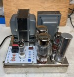
Tubes arrived - a box of shiny bling from China. All new Psvane rectifiers and KT88 power tubes.
Psvane seem to want to make everything look nice. The assembly of the tubes looks great, and they're packaged in bubble wrap and then sent in branded tube boxes that look beautiful. Except...
Two of four had defective heaters. The seller replaced them promptly and one of the two they shipped had a defective heater. Drag. And a 50% failure rate can (a) tell a lesson to buy from local reputable suppliers and (b) the reason the local suppliers sell at three and four times the price is probably because of high reject rates. Sigh...the rectifiers though were fine.
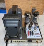
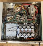
Anyway, as you can see from the pictures, the first of the two amplifiers is together and looking very pretty indeed, scratched and scuffed transformer endbells notwithstanding.
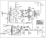
Initial testing went as follows - the initial power up was uneventful. Nothing went pop and the tubes warmed up as expected. Voltages came up and were near the nominal values. At first. But as it continued to warm up the B+ voltage settled in at 551V instead of 480V as it should be according to the schematic. The KT88s could go to their expected bias point of 1.56V at the bias resistor or 70 ish milliamps per tube.
The problem is that this is way too hot. The plate voltages were way over 525V and this puts the tubes into motorboating oscillation, way too much gain and early distortion.
I can turn the bias down to say 0.6V at the bias resistor or 2.5 mA per tube and the amp settles down a little (and starts to sound a bit better) but this isn't where the design points are. Not to mention that because it's an unregulated supply, things need to be just right voltage-wise and since the B+ is to high, the input and phase splitter tubes are also running too hot.
So I did a little probing and there's a 4.3V drop across the choke, which has a 62.7 ohm resistance, so that works out to 68.58 mA running through the choke at idle. And the supply is 71V on the hot side. So I want to drop 71V to get it down to 48V.
Some quick ohm's law figuring on the calculator says if I stick a 1035 ohm resistor in line with the choke I should be able to drop 71 volts at the 68.58 mA it's delivering. But dropping 71V across a resistor at 68 mA is 4.8 watts, so I'd need at least a 5W resistor or better.
Does this make sense to you guys? Would putting a 1K 10W resistor, say, before the choke do what I need it to do?
But now that almost everything has arrived, I've started the final assembly.
Tubes arrived - a box of shiny bling from China. All new Psvane rectifiers and KT88 power tubes.
Psvane seem to want to make everything look nice. The assembly of the tubes looks great, and they're packaged in bubble wrap and then sent in branded tube boxes that look beautiful. Except...
Two of four had defective heaters. The seller replaced them promptly and one of the two they shipped had a defective heater. Drag. And a 50% failure rate can (a) tell a lesson to buy from local reputable suppliers and (b) the reason the local suppliers sell at three and four times the price is probably because of high reject rates. Sigh...the rectifiers though were fine.
Anyway, as you can see from the pictures, the first of the two amplifiers is together and looking very pretty indeed, scratched and scuffed transformer endbells notwithstanding.
Initial testing went as follows - the initial power up was uneventful. Nothing went pop and the tubes warmed up as expected. Voltages came up and were near the nominal values. At first. But as it continued to warm up the B+ voltage settled in at 551V instead of 480V as it should be according to the schematic. The KT88s could go to their expected bias point of 1.56V at the bias resistor or 70 ish milliamps per tube.
The problem is that this is way too hot. The plate voltages were way over 525V and this puts the tubes into motorboating oscillation, way too much gain and early distortion.
I can turn the bias down to say 0.6V at the bias resistor or 2.5 mA per tube and the amp settles down a little (and starts to sound a bit better) but this isn't where the design points are. Not to mention that because it's an unregulated supply, things need to be just right voltage-wise and since the B+ is to high, the input and phase splitter tubes are also running too hot.
So I did a little probing and there's a 4.3V drop across the choke, which has a 62.7 ohm resistance, so that works out to 68.58 mA running through the choke at idle. And the supply is 71V on the hot side. So I want to drop 71V to get it down to 48V.
Some quick ohm's law figuring on the calculator says if I stick a 1035 ohm resistor in line with the choke I should be able to drop 71 volts at the 68.58 mA it's delivering. But dropping 71V across a resistor at 68 mA is 4.8 watts, so I'd need at least a 5W resistor or better.
Does this make sense to you guys? Would putting a 1K 10W resistor, say, before the choke do what I need it to do?
Attachments
A very easy workaround is using 5R4G rectifiers. 2A filament (close enough to the 5AR4), pin compatible, and 60V more forward voltage drop than a 5AR4. A very easy way to throw away the voltage that your 110v transformers are making on modern AC lines.
Just don't get one with “W” in the suffix, those are the potato masher and won’t fit in the area you have for the rectifier.
Just don't get one with “W” in the suffix, those are the potato masher and won’t fit in the area you have for the rectifier.
Interesting suggestion. Can the 5R4G rectifier handle the 41 uF of first stage capacitance I've built into the cap board?
The data sheet is nebulous on this topic.
The data sheet is nebulous on this topic.
It looks to me like the steady state peak diode current rating of the 5R4G is equivalent to the GZ34, but the hot-standby is a little uncertain for both tubes from their datasheets. I had a look at the GZ34 transient peak level and it seemed to be about 3.0A based on datasheet limit curve conditions when using PSUD2. The 5R4G datasheet also indicates 3.0A for capacitor input. It may be worthwhile to check the likely hot-turn-on peak expected in your amp by preparing a PSUD2 simulation.
Some data sheet say 20uF, some wartime say 4uF... might need a capacitor change.
That said, the resistor mod you speak of would work nicely.
That said, the resistor mod you speak of would work nicely.
These old ladies were built in a time of lower mains voltages, a desperate horsepower race, and affordable, excellent replacement valves. Allied catalog from 1965 has factory matched pairs of Genalex KT-88s for US$12.00, but all that's changed.
Two possibilities not yet (I think) mentioned are to reduce the value of the first B+ capacitor (maybe fly another one of same value in series mounted under chassis; use equal value parallel resistors for DCV balance and as bleeders. Or an external bucking transformer or even a dedicated Variac. Your heater voltages are also high, so the external transformer is most effective.
All good fortune,
Chris
Removing the first B+ cap will convert to a LC filter that will drop the voltage a lot. Easy to test.
However voltages with an unmodified MkIII :
AC input 237V , B+ at idle 516V biaset voltage 1.55Volt
AC input 237V , B+ at idle 516V biaset voltage 1.55Volt
Yes, these old hot-rods are challenging to restore and run today. At least they don't need leaded fuel. Arf!
There's a lot of discussion in tubes/valves about the B+ issues of Golden Age amplifiers, and they've lately coalesced around using a smaller first capacitor, maybe even a metallized polypropylene of single-digit size, and moving the existing first cap to the other side of the choke. The factory choke may not have enough inductance for real choke-input final voltage (not enough L for "critical inductance"), or may otherwise complain about being used at such high AC voltages, and a small first cap (slightly) mitigates these concerns.
The current term is "cLC", and the OP can find lots of discussion of it and PSUD software, needed to predict results, too complicated otherwise. Or, with a small collection of input caps, maybe several single digit values (buy two of each so you don't have to place a second order, and they're useful for crossovers) of some MPP 630V caps, just install, test, and stop changing when you've got a happy B+. Works for me, laziness and believability.
High heater voltages are a separate issue.
All good fortune,
Chris
Bear in mind that a dollar in 1965 is worth $9.55 today, so that $12 pair is about $100. Still, that's about half what a factory matched pair of modern tubes cost.These old ladies were built in a time of lower mains voltages, a desperate horsepower race, and affordable, excellent replacement valves. Allied catalog from 1965 has factory matched pairs of Genalex KT-88s for US$12.00, but all that's changed.
I recently rebuilt/modified a pair of Mk2's. With KT88's at about 50-55mA bias current I have around 500-510V B+. I'm using a CL-80 inrush limiter in the primary of the power transformer and SS diodes for rectification with a single damper diode in series for a slow start. The B+ rises to about 550V before the tubes start to conduct. Not sure why your B+ is so high once things are running. Are you certain the KT88's are running at 70mA? Is the cathode resistor accurate at 11.2 ohm? Seems like 140mA of bias current would pull the B+ down to some reasonable value. Is your meter reading accurately? I've had this happen before from the low batter. Just my wonderings.
John
John
Not sure why your B+ is so high once things are running. Are you certain the KT88's are running at 70mA? Is the cathode resistor accurate at 11.2 ohm? Seems like 140mA of bias current would pull the B+ down to some reasonable value. Is your meter reading accurately? I've had this happen before from the low batter. Just my wonderings.
I'm certain about the bias resistor. But biasing to 70 mA at 525V plate voltage is already 37 watts at idle, which is probably too much, I think.
The plate voltage is supposed to be 475V, so 70 mA cathode current makes 33 watts plate current at idle
.
Honestly I'm not 100% sure why the B+ is that high either. It could be a combination of factors, and most likely it is.
This is a resto-mod after all and not a "factory correct" restoration.
The changes are fairly broad:
- modern capacitors in the PSU section with increased capacitance, and I suspect much lower ESR
- change from the factory pentode-triode front end to triode (12AT7) - dual triode (6CG7) long tailed pair phase splitter )do these tubes consume less than the original 6AN8? I don't know.
- new production power tubes and rectifier (the front end has vintage NOS 12AT7 and 6CG7 tubes)
- higher line voltage (easily 120V here where I live and sometimes it goes higher at night)
I have a funny feeling that this new production Psvane GZ34 rectifier has a lower impedance than a vintage rectifier and a higher voltage output as a result. But I can't seem to find my spare vintage Mullard GZ34. It's got to be here somewhere...
I don't see where you mentioned the filament voltage you are seeing. If that is high, then something in the primary to reduce line voltage to the transformer would also help the B+. A CL-80 in series with the primary put my filament voltage quite close to 6.3VAC. This might help your situation as well. A bucking transformer at the input could do it as well. I used the SDS cap board too so I don't think it has much to do with the value of the B+.
John
John
That's a good point. I think it is pretty close.
I'll check when I get home this afternoon and report.
I'll check when I get home this afternoon and report.
The filament voltage is 6.62VAC. It is a bit high, but that's only 5% over voltage. I'm thinking that's probably within tolerance.I don't see where you mentioned the filament voltage you are seeing.
Inserting a 1K resistor in line with the rectifier output didn't help much - it lowered the B+ voltage quite a lot - down to like 420V and I couldn't get any decent bias on the KT88s - not even 15 mA per tube.
The happy medium was a 1K 5W parallel with a 500 Ohm 5W resistor (so 333 ohms) which got the B+ within range.
So now I am getting the following:
B+ Voltage: 486V
Plate Voltage: 485V
Screen Voltage: 485V
Bias Voltage: -62.4V
Biaset: 0.635V or 29 mA per tube.
This is a bit odd. If I bias any higher the output tubes go into motorboating oscillation. I can't get to the "correct" bias according to the manual.
I suspect that these new production tubes are at their limit within the circuit presented.
On the other hand, looking at the data sheet, 485V is at the far right of the Ia vs Va chart and the voltages on the tube agree with the predicted plate current on the data sheet chart.
At 29 mA and 485V that's 14 watts plate dissipation at idle. It's probably fine for idle current, no?
The amplifier sounds alright, too. Definitely needs some hours put on it.
Are you certain you don't have the overall phasing causing positive feedback? The boards I recently used for my Mk2's required crossing over the phase inverter stage to the opposite output tubes since there are a different number of stages in the circuit than the original. I had some funny things happening like you are until I realized this. You can be certain by measuring the output voltage using a known input voltage and then opening the global feedback. If the output voltage goes up then you have negative feedback. In my case I saw the output voltage drop when opening the feedback so I figured the feedback was the wrong polarity. I also had trouble getting a stable and correct bias current.
It would help if we knew the schematic.
It would help if we knew the schematic.
I did try that - I was unhappy with the results. The voltage did drop as predicted but removing the first stage of capacitance just made for a lot of power supply noise in the amplifier.Removing the first B+ cap will convert to a LC filter that will drop the voltage a lot. Easy to test.
I settled on reducing the stage 1 capacitance - from 41 uF to 34 uF and that dropped the voltage a little, allowing the use of a smaller in-line resistor (see my post above)
- Home
- Amplifiers
- Tubes / Valves
- Chronicling a Dynaco MK III resto-mod